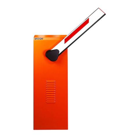
FAAC 596MPS User manual

!
"
#
$
"
%
&
'
(
"
)
*
&
+
!
"
#
%
(
,
(
!
&
%
&
UNI EN ISO 9001-085
para la naturaleza
100% papel reciclado
ist umweltfreundlich
100% Altpapier
pour la nature
papier recyclé 100%
for nature
recycled paper 100%
carta riciclata 100%
per la natura
!"#$%&
'
#()$%&
!"#$%&
'
#()$%&

Ti m b ro d e l Ri v e n d ito re : / D i st rib u t o r’ s St a m p :/ Tim b re d e l’ A g e n t :/ Fa c h h ä n d le rst e m p e l:/ Se l l o d e l Re v e n d e d o r:
Le d e sc rizio n i e le illu st ra zio n i d e l p re se n t e m a n u a le n o n so n o im p e g n a t iv e . La FA A C si rise rv a il d irit t o ,
la sc ia nd o ina ltera te le c a ra tteristic he e ssenzia li d ell’ a p p a rec c hia tura , d i a p p o rta re in q ua lunq ue
momento e senza impegnarsiad aggiornare la presente pubblicazione,le modifiche che essa ritiene
convenienti per miglioramenti tecnici o per qualsiasi altra esigenza di carattere costruttivo o
commerciale.
Th e d e sc r i p t i o n s a n d i l l u st r a t i o n s c o n t a i n e d i n t h e p r e se n t m a n u a l a r e n o t b i n d i n g . FA A C r e se rv e s t h e
rig ht, w hilst le a ving the m a in fe a tures o f the eq uip m ents una ltere d , to und e rta ke a ny mo d ific a tio ns
it hold s ne c essa ry fo r either tec hnic a l or c o mm erc ia l re a so ns, a t a ny time a nd w itho ut re vising the
present publication.
Le s d e sc rip t io n s e t le s illu st ra t io ns d u p ré se nt m a n u e l so nt fo u rn ie s à tit re in d ic a t if . FA A C se ré se rv e le
droitd’apporterà toutmomentlesmodificationsqu’elle jugera utilessurce produittoutenconservant
les c a ra c té ristiq ue s e ssentielle s, sa ns d e vo ir p our a uta nt m ettre à jo ur c e tte p ub lic a tio n.
Die Beschreibungen und Abbildungen in vorliegendem Handbuch sind unverbindlich. FAAC behält
sic h d a s Re c h t v o r, o h n e d ie w e se n t lic h e n Eig e n sc h a f t e n d ie se s G e rä t e s zu v e rä n d e rn u n d o h n e
Verbindlichkeiten in Bezug auf die Neufassung der vorliegenden Anleitungen, technisch bzw.
konstruktiv/ kommerziell bedingte Verb esserungen vorzunehmen.
La s d e sc rip c io n e s y la s ilust ra c io ne s d e e ste m a n u a l n o c o m p o rt a n c o m p ro m iso a lg u n o . FA A C se
reserva el d erec ho, d e ja nd o inmuta d a sla s c a ra c terístic a s ese nc ia les d e los a p a ra tos, d e a p orta r, e n
cualquier momento y sin comprometerse a poner al día la presente publicación, todas las
modificacionesque considere oportunaspara el perfeccionamiento técnico o para cualquier otro
tipo de exigencia de carácter constructivo o comercial.
FA A C S.p . A .
Via Benini, 1
40069 Zola Pred osa (BO) - ITALIA
Tel.: 051/6172411 - Tlx.: 521087
Fa x: 051/ 758518
FA A C p e r la n a t ura
•Lapresenteistruzioneèrealizzataal100%incartariciclata.
•Nondisperdetenell'ambientegliimballaggideicomponentidell'automazionebensìselezionate
i va ri m a te ria li (e s. c a rto ne , p o listirolo ) se c ond o p re sc rizioni lo c a li p e r lo sm a ltim ent o rifiuti e le
norme vigenti.
FA A C fo r t he e n viro n m e n t
• The p resent m anua l is p rod uc e d in 100% rec yc led p ap er
•Respecttheenvironment.Disposeofeachtypeofproductpackagingmaterial(card,polystyrene)
in a c c orda nc e w ith the p rovisions fo r w a ste d isp osa l a s sp ec ified in the c o untry of insta lla tion.
FA AC d e r Um w e lt zulie b e
•VorliegendeAnleitungensindauf100%Altpapiergedruckt.
•VerpackungsstoffederAntriebskomponenten(z.B.Pappe,Styropor)nachdeneinschlägigen
Normen der Abfallwirtsc haft sortenrein sammeln.
FA A C é c o lo g iq u e
•Laprésentenoticeaétéréalisée100%avecdupapierrecyclé.
•Nepasjeterdanslanaturelesemballagesdescomposantsdel’automatisme,maissélectionner
le s d iffé rents m a té ria ux (e x.: c a rto n, p o lyst yrè ne ) se lon la lég isla tio n lo c a le p o ur l’ é limina t ion d e s
déc hets et les normes en vigueur.
FA AC p o r la n a tura le za .
•Elpresentemanualdeinstruccionesseharealizado,al100%,enpapelreciclado.
•Losmaterialesutilizadosparaelembalajedelasdistintaspartesdelsistemaautomático(cartón,
poliestireno)nodebentirarsealmedioambiente,sinoseleccionarseconformealasprescripciones
loc a les y la s norm as vig entes para el d esec ho d e resid uos só lido s.
732320 - Rev.B
para la naturaleza
100% papel reciclado
ist umweltfreundlich
100% Altpapier
pour la nature
papier recyclé 100%
for nature
recycled paper 100%
carta riciclata 100%
per la natura

1
ITALIANO
ITALIANO
1) ATTENZIONE!Èimportante perla sicurezza delle persone seguire atten-
tamente tutta l’istruzione. Una errata installazione o un errato uso del
prodotto può portare a gravi danni alle persone.
2) Leg gere attentamente le istruzioni prima d i iniziare l’insta llazione d el
prodotto.
3) I m ateriali d ell’ imb alla gg io (p la stic a,p olistirolo,ec c .) no n d evo no es-
se re la sc ia t i a lla p o rt a ta d e i b a m b in i in q u a n t o p o t e nzia li fo n t i d i
pericolo.
4) Conserva re le istruzioni p er riferimenti futuri.
5) Questo prod otto è sta to prog etta to e c ostruito esc lusiva mente p er
l’ utilizzo ind ic a t o in q ue sta d o c um e nta zio ne. Qua lsia si a ltro ut ilizzo no n
espressamente indicato potrebbe pregiudicare l’integrità delprodot-
to e/o rappresentare fonte di pericolo.
6) FAAC dec lina qualsiasi resp onsa b ilità deriva ta dall’ uso improp rio o
diverso da quello percuil’automatismo è destinato.
7) Non installare l’ap p arec c hio in atmosfera esplosiva : la p resenza d i gas
o fumi infiammabili costituisce un grave pericolo per la sicurezza.
8) Gli elem enti c ostruttivi m ec c a nic i d evono esse re in a c c ord o c on
quanto stabilito dalle Normative UNI8612, CEN prEN 12604 e CEN pr
EN 12605.
Pe r i Pa e si e xt ra -C EE, o lt re a i rife rim e n ti no rm a t ivi n a zio n a li, p e r o t te n e -
re un livello d i sic urezza a d e g ua to, d evo no essere se g uite le No rme
so p ra rip o rt a t e .
9) FAAC no n è responsa bile d ell’ inosserva nza della Buona Tecnic a nella
costruzione delle chiusure da motorizzare,nonchè delle deformazioni
che dovessero intervenire nell’utilizzo.
10) L’installazione d eve essere effettua ta nell’osserva nza delle Norme
UNI8612, CEN p r EN 12453 e C EN p r EN 12635.
Il liv e llo d i sic ure zza d e ll’ a ut o m a zio n e d e v e e sse re C +D.
11) Prima d i effettua re qualsia si intervento sull’impia nto, togliere l’a limen-
tazione elettrica.
12) Preved ere sulla rete d i alimenta zione dell’automazione un interruttore
onnipolare con distanza d’apertura deicontattiuguale o superiore a
3 m m. Èc onsigliab ile l’ uso d i un ma g ne to termic o d a 6A c o n inte rruzio-
ne onnipolare.
DICHIARAZIONE CE DI CONFORMITÁ
Fa b b ric a nte : FA A C S.p . A .
Indirizzo: Via Benini, 1 - 40069 Zola Predosa BOLOGNA - ITALIA
Dichiara che: Le a p p a re c c h ia t u re e le tt ro nic h e 596M PS e 610M PS
•sonoconformiairequisitiessenzialidisicurezzadelleseguentidirettive:
73/ 23/ CEE e suc c essiva modific a 93/ 68/ CEE.
89/ 336/ CEE e suc c essiva mod ifica 92/ 31/ CEE e 93/ 68/ CEE
Nota aggiuntiva :
Questi prodotti sono stati sottoposti a test in una configurazione tipica omogenea (tutti prodotti di costruzione
FA A C S.p . A . )
Bo lo g n a , 01, g e n n a io ,1999
L’ A m m in ist ra t o re D e le g a t o
A. Bassi
13) Verific are che a monte d ell’impianto visia un interruttore differenziale
con soglia da 0,03A.
14) Verific a re c he l’ imp ianto di terra sia realizzato a regola d’ arte e
collegarvile partimetalliche della chiusura.Collegare inoltre a terra
il filo Gia llo / Ve rd e d e ll’ a uto ma tism o.
15) L’a utomazione dispone diuna sicurezza intrinseca antisc hiac ciamento
costituita da un controllo di coppia che deve comunque essere
se m p re a c c o m p a g n a t o a d a lt ri d isp o sit iv i d i sic u re zza .
16) I d isp ositivi d i sic urezza (Es.: fo to c ellule,c o ste sensib ili,ec c ...) p ermet-
tono diproteggere eventualiaree dipericolo da Risc hi m e c c a n ic i d i
movimento, c om e a d Es. sc hiac c ia me nto, c o nvog liam ento,
cesoiamento.
17) Per ogni imp ianto è ind ispensabile l’utilizzo d i a lmeno una segnala-
zio n e lu m in o sa ( e s: FA A C LA M P M INILA M P, e c c .) n o n c h è d i u n c a rt e llo
di segnalazione fissato adeguatamente sulla struttura dell’infisso,
oltre ai dispositivi citati al punto “16”.
18) FAAC dec lina ogni responsabilità ai fini d ella sic urezza e d el b uon
funzionamento dell’automazione, in caso vengano utilizzati compo-
nenti dell’impianto non di produzione FAAC.
19) Per la manutenzione utilizza re esc lusivamente p arti origina li FAAC.
20) Non ese guire a lc una m od ific a sui c o mp o nenti fa c enti p arte il sistem a
d’automazione.
21) L’ installatore deve fornire tutte le informa zioni relative al funziona-
mento manuale del sistema in caso di emergenza e consegnare
all’Utente utilizzatore dell’impianto illibretto d’avvertenze allegato al
prodotto.
22) Non permettere ai bam bini o p ersone di sosta re nelle vic inanze d el
prodotto durante ilfunzionamento.
23) Tenere fuori dalla portata dei bambini radioc omandi o q ualsia si a ltro
datore di impulso,perevitare che l’ a uto ma zio ne p o ssa e sse re
azionata involontariamente.
24) L’ Utente utilizzatore d eve a stenersi da q ualsia si tentativo d i ripa ra zio-
ne o d’intervento diretto e rivolgersi solo a personale qualificato.
25) Tutto quello che non è previsto espressamente inqueste istruzioninon
è permesso
AVVERTENZE PER L’INSTALLATO RE
OBBLIGHI GENERALI PERLA SICUREZZA

2
ITALIANO ITALIANO
Le p re se n t i istru zio n i so n o va lid e p e r i se g u e nt i m o d e lli:
Apparecchiature 596MPS - 610MPS
1. DESCRIZIONE
L'a p p a re c c h ia t u ra e le t t ro n ic a 596M PS è in d ic a t a p e r
comandare automazioni basculanti con singolo o doppio
operatore oleodinamico.
L'a p p a re c c h ia t u ra e le t t ro n ic a 610M PS è in d ic a t a p e r
comandare barriere con operatore oleodinamico.
1.1. CARATTERISTICHE TECNICHE
TA B. 1 PA RA M ETRI DI FUNZIO NAM ENTO 596M PS & 610M PS
(selezionabili a dip-switch)
596MPS 610MPS
Lo g i c a automatica (A) / semiautomatica (E)
Te m p o p a u sa ( se c . ) 30/ 60 0/ 2/ 5/ 10/ 15/ 30/ 60
Te m p o l a v o ro ( se c . ) 25/ 30/ 35/ 40 4/ 5/ 7/ 9
Fa ilsa fe abilitato/disabilitato
TA B. 2 CARATTERISTICHEHARDWARE 596MPS& 610MPS
Alimentazione 230V~ (+6 -10 %) 50Hz
Pote nza m a x a ssorb ita 10 W
Carico max motori 800 W
Alimentazione accessori 24Vdc
Carico max accessori 250 mA
Te m p e ra t u ra a m b i e n te - 20°C
!
+ 55°C
Fusib ili d i p ro te zio ne motore/accessori
Connettori rapidi per schede decodifica-riceventi RP
pulsante apertura esterno
Morsettiere estraibili
Open
Ingressi in morsettiera St o p
Si c u r e zz e i n c h i u su r a
Fin e c o rsa
Usc ite in m orse ttie ra motore
condensatore
alimentazione accessori 24Vdc
la m p a d a d i c o rte sia (596MPS)
la m p eg g ia to re (610M PS)
Te m p o r i z z a z i o n e d i c o r t e si a 90 sec . (596MPS)
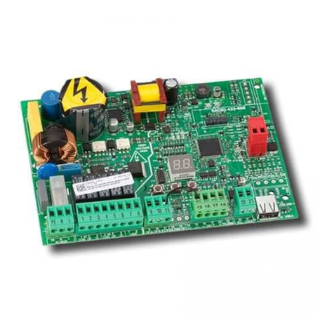
1.2. LAY OUT SCHEDA 596MPS & 610MPS
2. COLLEGAMENTI ELETTRICI
!Prim a d i e ffe ttua re q ua lsia si tip o d i inte rve nto sulla sc he d a
(collegamenti, programmazione, manutenzione) togliere sem-
pre l’alimentazione elettrica.
Se g u i r e i p u n t i 1 0 , 1 1 , 1 2 , 1 3 , 1 4 d e g l i O BBLIG H I G EN ERA LI PER LA
SIC UREZZA .
Se p a r a r e se m p r e i c a v i d i a l i m e n t a zi o n e 2 3 0 V ~ d a q u e l l i d i
comando e disicurezza (pulsanti,ricevente,fotocellule ecc.).
Pe r e vit a re q u a lsia si d isturb o e le tt ric o utilizza re g ua in e se p a ra te .
2.1. SCHEMA COLLEGAMENTO 596MPS
(fotocellula con failsafe abilitato)
2.2. SCHEMA COLLEGAMENTO 610MPS
(fotocellula con failsafe abilitato)
876543219
16151413121110
1817 19
!"
#"
!$
%&'
'"($)*
+,
-#'
#'
!'
!(
./'
!0
12'
12(
12"
F1
J4
J9
J3
DS1
J1 J2
F2
!'
-
.
/
0
1
0
1
M1 M2
!"#$
%&&
%'(
')!"
*+,-
%./01'.%#
%&.
!"
!0
'#2-//45)
+67-83,7(39:;
%..&0.<"
</$/0.<"
C1
C2
TXRX
-23$45
.=>?@3ABCD?@EE@
!>F@?3A:G@>B@A
.D>?@A3AHCD?B>HA
.IJ@?@3'BCF@?F@B>@I
!>?KA3JBALM3A@NM
230V~
(+6% -10%)
50Hz
8
7
654
3
219
16
15
14
13121110
1817 19
!'
-
.
/
0
1
0
1
230V~
(+6% -10%)
50Hz
M1 M2
!"#$
%&&
%'(
')!"
*+,-
%./01'.%#
%&.
!"
!0
%..&0.<"
</$/0.<"
C1
C2
TXRX
316$45
.=>?@3ABCD?@EE@
!>F@?3A:G@>B@A
.D>?@A3AHCD?B>HA
.IJ@?@3'BCF@?F@B>@I
!>?KA3JBALM3A@NM
8
7
654
3
219
16
15
14
13121110
1817 19
TA B. 3 COMPONENTI SCHEDA 596MPS& 610MPS
F1 Fu sib ile F1 5x20 5A / 2 5 0V ( m o t o re / p rim a rio t ra sf o rm a t o re )
F2 Fu sib ile F2 5x20 0 .5A / 250V rit a rd a t o ( a lim e n t a zio n e a c c e sso ri)
DS1 Microinterruttori di programmazione
J1 Morsettiera bassa tensione ingressi/accessori
J2 Morsettiera uscita motore/condensatore/lampada
J3 Connettore rapido schede decodifica/riceventi RP
J4 Connettore rapido pulsante Open
J9 Morsettiera ingresso alimentazione 230V~
Fig . 2
Fig . 3
Fig . 1
596MPS & 610MPS

3
ITALIANO
ITALIANO
3. DESCRIZIONECOLLEGAMENTI
3.1. MORSETTIERA J1 (bassa tensione)
1 = Comando di OPEN (N.O.)
Si i n t e n d e q u a l si a si d i sp o si t i v o ( p u l sa n t e , d e t e c t o r, . . )
che,chiudendo un contatto,può dare un impulso
d’apertura o chiusura all'automazione.
Pe r in st a lla re p iù d isp o sit iv i d i O p e n , c o lle g a re i c o n -
tatti N.O. in parallelo.
2 = FSW Contatto sicurezze in chiusura (N.C.)
Pe r sic u re zze , si in t e n d o n o t u t t i i d isp o sit iv i
(fotocellule, coste sensibili, spire magnetiche) con
contatto N.C. che intervengono in presenza di un
ostacolo nell’area da loro protetta.
Le sic u re zze sa lva g ua rd a n o la zo na int e re ssa ta d a l
movimento in chiusura dell'automazione.
L’ i n t e r v e n t o d e l l e si c u r e z ze d u r a n t e l a f a se d i c h i u -
su ra p ro vo c a l’ inv e rsio n e d e l m o v im e n t o d e ll'a u t o -
mazione, mentre non ha effetto durante la fase di
apertura.Le sicurezze impegnate ad automazione
aperta o in pausa,impediscono la chiusura.
Pe r in st a lla re p iù d isp o sit iv i d i sic u re zza , c o lle g a re i
contatti N.C.in serie.
!Se n o n v e n g o n o c o l l e g a t i d i sp o si t i v i d i si c u r e zza
in c hiusura , p o ntic e lla re q uesto ing resso :
•colmorsetto 4(se failsafe disabilitato),oppure
•colmorsetto 6(se failsafe abilitato).
3 = Comando di STOP (N.C.)
Si i n t e n d e q u a l si a si d i sp o si t i v o ( e s. p u l sa n t e ) c h e ,
aprendo un contatto,arresta il movimento dell'au-
tomazione.
Pe r in st a lla re p iù d isp o sit ivi d ’ a rre sto , c o lle g a re i c o n -
tatti N.C. in serie.
!Se n o n v e n g o n o c o l l e g a t i d i sp o si t i v i d i St o p ,
ponticellare l’ingresso col comune (morsetto 4).
4 = Comune contatti/ Negativo alimentazione accessori (-)
5 = Positivo alimentazione accessori 24Vdc (+)
Il c a ric o m a x d eg li a c c esso ri è 250m A.
Pe r il c a lc o lo d e g li a sso rb im e n ti, fa re rife rim e n to a lle
istruzioni d ei sing oli ac c esso ri.
6 = Failsafe (-) (vedi "
4. Programmazione
")
Se si a b i l i t a i l Fa i l sa f e , c o l l e g a r e o b b l i g a t o r i a m e n t e
a questo morsetto i negativi dei proiettori
fotoc ellule.
7 = FCC Contatto Finecorsa Chiusura (N.O.)
Il fine c o rsa d i c hiu su ra è un d isp o sit ivo c o n c o nta t -
to N.O. che, azionato quando l'automazione rag-
giunge la posizione di chiuso (chiudendo il contat-
to), provoca l'arresto dell'automazione dopo circa
1 sec ond o.
8 = Comune contatti/ Negativo alimentazione accessori (-)
9 = FCA Contatto Finecorsa Apertura (N.O.)
Il fine c o rsa d i a p e rt ura è un d isp o sitivo c o n c o n ta t -
to N.O. che, azionato quando l'automazione rag-
giunge la posizione di aperto (chiudendo il contat-
to), provoca l'arresto dell'automazione.
3.2. MORSETTIERA J2 (alta tensione)
10-11 = Collegamento condensatore di spunto
In c a so d i a p p lic a zio n e c o n d ue o p e ra to ri, c o lle g a -
re in p a ra lle lo i c o nd e nsa tori.
12-13-14 = Collegamento motore elettrico
I m o rse tt i 12-13 va nn o c o lle g a t i a lle fa si d e l m o t o re
(cavi marrone e nero) mentre il morsetto 14 al co-
mune del motore (cavo blu).
In c a so d i a p p lic a zio n e c o n d ue o p e ra to ri, c o lle g a -
re in p a ra lle lo i d u e m o t o ri.
15-16 = Lampada cortesia temporizzata (596MPS)
La m p e g g ia t o re ( 6 1 0 M PS)
La fu n zio n e d i q u e sta u sc it a è d iffe re nzia t a in b a se
al modello di scheda:
•596MPS:
Collegare l'eventuale lampada di cortesia 230V~
60W max. La luc e di c ortesia si attiva alla p artenza
delmotore e permane perun tempo dicirca 90 se-
condi dal termine del movimento.
•610MPS:
Collegare il lampeggiatore 230V~ 60W max.
3.3. CONNETTORE J3 (bassa tensione)
Il c o nn e tt o re J3 è u tilizza to p e r il c o lle g a m e n to ra p id o d i
sc h e d e M INID EC ,DEC O DER, RIC EVENTI RP ( Fig . 4,5,6)
L'in se rim e n t o a v v ie n e in n e st a n d o le sc h e d e a c c e sso rie in
maniera che il loro lato componenti sia rivolto verso l'interno
dell'apparecchiatura elettronica.
Inse rim e n to e d isin se rim e nto va nn o e ffe tt ua ti d o p o a v e r t o lt o
tensione.
3.4. CONNETTORE J4 (bassa tensione)
Il c o nn e tt o re J4 è ut ilizza t o p e r il c o lle g a m e n to ra p id o d e l
pulsantediaperturapostosulcarterdioperatoriperbasculante.
3.5. MORSETTIERA J9 (alta tensione)
Morsettiera per collegare l'alimentazione 230V~ 50Hz.
(L=Linea - N=Neutro - !=Terra).
4. PROGRAMMAZIONE
Pe r p ro g ra m m a re il funzio na m en t o d e ll'a uto m a zio ne , a g ire sui
microinterruttori come segue:
Te m p o A p / C h ( se c . ) SW 3 SW4
40 OFF OFF
35 ON OFF
30 OFF ON
25 ON ON
Comportamento FSW SW2
apre immediatamente OFF
apre al disimpegno ON
123456
ON
OFF
Fa ilsa fe SW6
No OFF
Si O N
Te m p o Pa u sa ( se c . ) SW 5
30 OFF
60 ON
Lo g i c a SW1
EOFF
AON
596MPS
123456
ON
OFF
Lo g i c a Pa u sa SW1 SW2 SW 3
(sec.)
E/OFFOFFOFF
0ONOFFOFF
2OFFONOFF
5ONONOFF
A10OFFOFFON
15 ON OFF ON
30 OFF ON ON
60 ON ON ON
Te m p o A p / C h SW4 SW 5
(sec.)
4OFFOFF
5ONOFF
7OFFON
9ONON
Fa ilsa fe SW6
No OFF
Si O N
610MPS
MINIDEC
SL/DS
PLUS
844MPS
DECODER
SL/SLP/DS
844MPS
844MPS
Fig .4 Fig . 6Fig . 5
4
ITALIANO ITALIANO
•Logiche difunzionamento
Il c o m p o rta m e n to d e ll'a ut o m a zio ne ne lle lo g ic he :
A = Automatica E= Semiautomatica
è indicato nelle Tab. 4-5.
•TempoPausa
É il t e m p o d i so st a in a p e rt u ra p rim a d e lla ric h iu su ra , q u a n d o
si se le zio n a la lo g ic a a u t o m a t ic a .
•Tempo Apertura/Chiusura
Se l e zio n a r e u n t e m p o d i m o v im e n t o c h e p e r m e t t a d i
mantenere ilmotoreelettrico alimentatoperqualchesecondo
dopo l'arrivo dell'automazione sugli arresti meccanici.
Ra p p re se n t a a n c h e il t e m p o m a ssim o p e r ra g g iu n g e re i
finecorsa (opzionali).
•ComportamentoFSW(solo596MPS)
Definisce l'effetto dell'intervento delle sicurezze durante la
chiusura (inversione immediata o aldisimpegno).
Nota: la 610MPSesegue solo l'inversione immediata.
•Failsafe
Il Fa ilsa fe è un sist e m a e le t tro nic o d i ve rific a d e lla fu nzio n a lità
delle fotocellule collegate.Ilcontrollo viene effettuato prima
di ogni azionamento in chiusura dei motori, disalimentando
momentaneamente il proiettore (TX) della fotocellula per
accertare la conseguente apertura delcontatto sulricevitore
(RX).Qualora ciò non avvenga,ilmovimento dell'automazione
è inibito per sicurezza.
L'a b ilit a zio ne d e l Fa ilsa fe ric h ie d e
un'alimentazione separata per i proiettori delle fotocellule
(Fig.12).
8
7
654
3
219
8
7
654
3
219
-
.
/
0
1
0
1
TXRX
8
7
654
3
219
8
7
654
3
219
8
7
654
3
219
-
.
/
0
1
0
1
TXRX
8
7
654
3
219
6. ESEMPI DI COLLEGAMENTO SICUREZZE
!FAILSAFE disabilitato (SW6=OFF)
J1
J1
J1
J1
J1
J1
Fig . 1 0
Fig . 1 1
Fig . 1 2
Fig . 8
Fig . 9
Fig . 7
5. MESSA IN FUNZIONE
Insta lla re la sc he d a in c o nte nitori c o n a d e gua to g ra d o d i
protezione. Gli accessori per il cablaggio (passacavi,tubi,...)
devono mantenere il grado di protezione del contenitore.
5.1. VERIFICA DELSENSO DI ROTAZIONE
1) Togliere la tensione d i alimentazione a lla sc heda.
2) Sb loc c a re l'a utom azione, a gend o sul d isp ositivo d i b lo c -
co/sblocco degli operatori.
3) Porta re ma nualmente l'automazione a metà della sua
corsa.
4) Rib loc c a re l'a uto ma zione, a gend o sul d isp ositivo d i b loc -
co/sblocco degli operatori.
5) Ripristinare la tensione d i a limenta zione alla sc heda.
6) Inviare un impulso di a pertura (Open) e verificare che si
comandil'apertura dell'automazione.
Qualora uno o entrambiimotorivenissero azionatiin chiusura,
invertirne le fa si (c a vi ma rrone e nero) sulla morsettiera d ella
sc h e d a .
Collegamento di nessun dispositivo di sicurezza
Collegamento di una costa di sicurezza
Collegamento di una coppia di fotocellule
7. ESEMPI DI COLLEGAMENTO SICUREZZE
!FAILSAFE abilitato (SW6=ON)
TA B. 4 LO G IC A A UTO M A TIC A ( A )
LO G I C A "A " I M PULSI
STA TO A UTO M A ZI O N E O PEN STO P SI C UREZZE
CHIUSO apre e richiude dopo il nessun effetto nessun effetto
tempo pausa (Open inibito)
IN A PERTURA ne ssu n e ffe t to b lo c c a il ne ssu n e ffe t to
funzionamento
APERTA IN PAUSA richiude blocca il ferma la pausa
im me d ia ta m e nte funziona m e nto fino a l d isim p e gno
IN C HIUSURA ria p re b lo c c a il in ve rt e il m o t o
im me d ia ta m e nte funziona m e nto (!)
BLO C C A TA ric hiu d e n e ssun e f fe t t o n e ssun e f fe t t o
(Open inibito) (Open inibito)
TA B. 5 LO G IC A SEM IA UTO M A TIC A (E)
LO G I C A "E" I M PULSI
STA TO A UTO M A ZI O N E O PEN STO P SI C UREZZE
CHIUSO apre nessun effetto nessun effetto
(Open inibito)
IN A PERTURA si b lo c c a b loc c a il nessun e ffetto
funzionamento
APERTA ric hiud e nessun e ffetto ne ssun effe tto
im me d ia ta m e nte (O p en inib it o) (O p en inib ito )
IN C HIUSURA ria p re b lo c c a il in ve rt e il m o t o
im me d ia ta m e nte funziona m e nto (!)
BLO C C A TA ric hiu d e n e ssun e f fe t t o n e ssun e f fe t t o
(Open inibito) (Open inibito)
(!) • 596MPS= vedi SW2 • 610MPS=inverte immediatamente
Collegamento di nessun dispositivo di sicurezza
Collegamento di una costa di sicurezza
Collegamento di una coppia di fotocellule

5
EN G LI SH
EN G LI SH
1) CAUTION!Itisimportant forpersonalsafety to follow all the instructions
carefully. Incorrect installation or misuse of the product may cause
people serious harm.
2) Re a d t h e in st ru c t io n s c a re fu lly b e f o re st a rt in g t o in st a ll t h e p ro d u c t .
3) Pa c ka g in g m a t e ria l (p la stic , p o lyst yre n e , e t c .) m ust no t b e le ft w it hin re a c h
ofchildrenasitisa potentialsource ofdanger.
4) Ke e p t he instru c t io n sin a sa f e p la c e f o r fu tu re re fe re n c e .
5) Thisp ro d uc t w a sd e sig ne d a nd m a nufa c t ure d stric t ly fo rt he use ind ic a ted
in thisd o c um enta tio n. Any o the rno t e xp ressly ind ic a ted use m a y d a m a g e
the product and/orbe a source of danger.
6) FA A C a c c e p t sn o re sp o nsib ilit y d u e t o im p ro p e r u se o f t he a u to m a t io n o r
use otherthanthat intended.
7) Do no t in st a ll the a p p lia nc e in a n a re a sub je c t to e xp lo sio n ha za rd : infla m -
mable gassesorfumesare a serioussafetyhazard.
8) M e c h a nic a l c o nstru c t io n e le m e n tsm u st m e e t t he p ro v isio ns o f UNI8612,
CENprEN12604and CENprEN12605Standards.
To o b t a i n a n a d e q u a t e l e v e l o f sa f e t y i n n o n EU c o u n t r i e s, t h e a b o v e
mentioned Standardsmustbeobserved inadditiontonationalstandards.
9) FA A C w ill no t a c c e p t re sp o nsib ilit y if t he p rinc ip le so f G o o d Wo rkm a n ship
aredisregardedinconstructing theclosingelementstobemotorised,and
if a ny d efo rma tio n o c c ursd uring use o f the sa id e lem ents.
10) Insta lla tio n m ust m e et the fo llo w ing St a nd a rd s: UNI8612, C EN p r EN 12453
and CENprEN12635.
Th e sa f e t y c l a ss f o r t h e a u t o m a t i o n m u st b e C + D .
11) Be fo re c a rryin g o u t a ny w o rk o n t he syste m , sw it c h o ff t he p o w e r sup p ly.
12) Th e m a insp o w e r su p p ly o f th e a ut o m a t io n m u st b e fitt e d w it h a a ll-p o le
sw it c h w it h c o n t a c t o p e n in g d ist a n c e o f 3m m o r g re a t e r. Use o f a 6 A
thermalbreakerwith all-pole circuit breakisrecommended.
13) M a ke sure the re isa d iffe re ntia l sw itc h w ith 0.03A thre sho ld up stre a m o f the
sy st e m .
14) C hec k tha t the e arthing syste m isc orrec tly ma de a nd c onne c t the c lo sure
metalpartstoit.Alsoconnectthe Yellow/Greenwire oftheautomationto
the earthing system.
CE DECLARATION OF CONFORMITY
Manufacturer: FA A C S.p .A .
Address: Via Benini, 1 - 40069 Zola Predosa BOLOGNA - ITALY
Declares that: Ele c t ro n ic a p p lia n c e s 5 96 M PS a n d 610M PS
•conformtotheessentialsafetyrequirementsofthefollowing directives:
73/ 23/ EEC a nd sub sequent a mend ment 93/ 68/ EEC.
89/ 336/ EEC a nd sub sequent amendment 92/ 31/ CEE a nd 93/ 68/ EEC
Additional information:
Th e se p r o d u c t s u n d e r w e n t t e st s i n a t y p i c a l , u n i f o r m c o n f i g u r a t i o n ( a l l p r o d u c t s m a n u f a c t u r e d b y FA A C
S. p . A . ) .
Bo lo g n a 01 Ja n u a ry 199 9
Th e M a n a g i n g D i r e c t o r
A. Bassi
15) Th e a u to m a t io n in c lud e sa n intrinsic a n ti-c rush ing d e vic e c o n sist in g o f a
torque control which, however, must be installed together with other
sa f e t y d e v ic e s.
16) The sa fe ty d evic e s[ e .g .: p ho to c e lls, sensitive e d g es, e tc …] p ro tec t a ny
dangerousareasagainstM o v e m e nt m e c ha nic a l risk s, suc h a s, c rushing ,
dragging,orshearing.
17) Use of at least one ind icator-lig ht isessentialforea c h system (e.g.:FAAC
LA M P M INILA M P, e tc .) a s w e ll a s a sig n a d e q ua te ly f ixe d t o t h e fra m e
struc ture, in a d d ition to the d evic esmentioned a t p oint “ 16” .
18) FAA C a c c e p tsno re sp o nsib ility re ga rd ing sa fety a nd c o rre c t o p era tio n
ofthe automation, should componentsmade bymanufacturersother
than FAAC be used inthe system.
19) Use o nly FAAC o rig ina l sp a re p a rtsfo r m a int ena nc e .
20) Do no t m a ke a ny a lte ra tio nsto the c o m p onent so f t he a uto m a tio n.
21) The insta lle r must sup p ly full info rm a tio n re ga rd ing m a nua l op e ra tio n o f
the system in case of an emergencyand hand to the userof the system the
“User’sGuide”includedwiththeproduct.
22) Do n o t a llo w c h ild re n o r o t he r p e rso nsto st a n d ne a r t he p ro d u c t w h ile in
operation.
23) Ke e p re m o t e c o n tro lso r a n y o t he r p ulse g e ne ra t o r w e ll a w a y fro m c h il-
d ren, to p re ve nt the a utoma tion from b eing a c tiva ted a c c identa lly.
24) The user m ust refra in from a tte mp ting to re p a iro ra d just the syste m p e rso n-
allyandshould contactqualifiedpersonnelonly.
25) Anything not expressly provided for in these instructions is not
permitted.
WARNING FO R THE INSTALLER
GENERAL SAFETY OBLIGATIONS

6
EN G LI SH EN G LI SH
Th e se i n st r u c t i o n s a p p l y t o t h e f o l l o w i n g m o d e l s:
Appliances 596MPS- 610MPS
1. DESCRIPTION
Th e 5 9 6 M PS e l e c t r o n i c a p p l i a n c e i s su i t a b l e f o r c o n t r o l l i n g u p -
and-over automatic systemswith single or double hydraulic
operator.
Th e 6 1 0 M P Se l e c t r o n i c a p p l i a n c e i s su i t a b l e f o r c o n t r o l l i n g b a r r i e r s
witha hydraulic operator.
1.1. TEC H N I C A L SPEC I FI C A TI O N S
TA BLE 1 OPERATING PARAMETERS OF596MPS& 610MPS
(dip-switch selectable)
596MPS 610MPS
Lo g i c automatic (A) / semi-automatic (E)
Pa use tim e ( se c .) 30/ 60 0/ 2/ 5/ 10/ 15/ 30/ 60
Work time (sec.) 25/ 30/ 35/ 40 4/ 5/ 7/ 9
Fa ilsa fe enabled/disabled
TA BLE 2 HARDWARECHARACTERISTICSOF596MPS& 610MPS
Po we r sup p ly 230V~ (+6 -10 %) 50Hz
Max absorbed power 10 W
Motors max. load 800 W
Powe r supp ly fo r a c c e ssorie s 24Vdc
Accessories max. load 250 mA
Ambient temperature - 20°C !+ 55°C
Fuse s motor/accessories
Ra p id c o nn e c to rs for decoding-RP receiver cards
push-button for outside opening
Te rm i n a l b o a rd s rem ova b le
Open
Te rm i n a l b o a r d i n p u t s St o p
Closure safety devices
Lim it -sw it c h
Te rm i n a l b o a rd o u t p u t s motor
capacitor
24 Vd c a c c essories p ow er sup p ly
courtesy light (596MPS)
flashlight (610MPS)
Courtesy timing 90 sec . (596MPS)
1.2. LA Y- O UT O F 5 6 9 M PS & 6 1 0 M PS C A RD
2. ELECTRICAL CONNECTIONS
!
Be fo re a tte m p ting a ny w o rk o n the c a rd ( c o nne c tio ns,
programming, maintenance), always turn off power.
Observepoints10,11,12,13and14ofthe GENERALSAFETYRULES.
Alwaysseparate 230V~ powercablesfrom controland safety
cables(push-button receiver,photocells,etc.).
To p r e v e n t a n y e l e c t r i c n o i se w h a t e v e r , u se se p a r a t e sh e a t h s.
2.1. 596MPS CONNECTION LAY-OUT
(photocell with failsafe enabled)
2.2. 610MPS CONNECTION LAY-OUT
(photocell with failsafe enabled)
876543219
16151413121110
1817 19
!"
#"
!$
%&'
'"($)*
+,
-#'
#'
!'
!(
./'
!0
12'
12(
12"
F1
J4
J9
J3
DS1
J1 J2
F2
!'
-
.
/
0
1
0
1
M1 M2
!"#$
%&&
%'(
')!"
*+,-
%./01'.%#
%&.
!"
!0
'#2-//45)
+67-83,7(39:;
%..&0.<"
</$/0.<"
C1
C2
TXRX
-23$45
.=>?@3ABCD?@EE@
!>F@?3A:G@>B@A
.D>?@A3AHCD?B>HA
.IJ@?@3'BCF@?F@B>@I
!>?KA3JBALM3A@NM
230V~
(+6% -10%)
50Hz
8
7
654
3
219
16
15
14
13121110
1817 19
!'
-
.
/
0
1
0
1
230V~
(+6% -10%)
50Hz
M1 M2
!"#$
%&&
%'(
')!"
*+,-
%./01'.%#
%&.
!"
!0
%..&0.<"
</$/0.<"
C1
C2
TXRX
316$45
.=>?@3ABCD?@EE@
!>F@?3A:G@>B@A
.D>?@A3AHCD?B>HA
.IJ@?@3'BCF@?F@B>@I
!>?KA3JBALM3A@NM
8
7
654
3
219
16
15
14
13121110
1817 19
TA BLE 3 COMPONENTSOF596MPS& 510MPSCARD
F1 Fu se F1 5x20 5 A / 250V ( m o t o r/ t ra n sf o rm e r p rim a ry w in d in g )
F2 Fu se F2 5x20 0. 5A / 250V d e la y e d (a c c e sso rie sp o w e r su p p ly )
DS1 Pro g ra m m in g m ic ro sw itc h e s
J1 Lo w v o lt a g e in p u t/ a c c e sso rie s t e rm in a l b o a rd
J2 Outputterminalboard formotor/capacitor/lamp
J3 Ra p id c o n n e c t o r f o r d e c o d in g / RP re c e iv e r c a rd s
J4 Ra p id c o n n e c t o r fo r O p e n p u sh -b u t t o n
J9 230V powersup ply inp ut termina lboa rd
Fig . 2
Fig . 3
Fig . 1
596MPS & 610MPS

7
EN G LI SH
EN G LI SH
3. WIRING DESCRIPTION
3.1. TERM I N A L BO A RD J1 ( l o w v o l t a g e )
1 = OPEN command (N.O.)
Any device (push-button,detector,…) which,by closing a
contact,suppliesanopening orclosing pulse to the auto-
matic system.
To i n s t a l l se v e r a l O p e n d e v i c e s , c o n n e c t N . O . c o n t a c t s i n
parallel.
2 = FSW Closing safety devices contact (N.C.)
Sa f e t y d e v i c e s a re a l l d e v i c e s ( p h o t o c e l l s, se n sit iv e e d g e s,
magnetic coils) with N.C.contact,which operate if there is
an obstacle in the area they protect.
Sa f e t y d e v i c e s p ro t e c t t h e a r e a a f f e c t e d b y t h e c lo sin g
movement of the automatic system.
If t he sa fe t y d e vic e s a re t rip p e d d uring c lo sure , a ut o m a t ic
movement isreversed,whereasthey hasno effect during
opening. The safety devicesoperating when the auto-
matic system isopen orpausing,prevent closure.
To i n s t a l l se v e r a l s a f e t y d e v i c e s , c o n n e c t t h e N . C . c o n t a c t s
in series.
!If n o c lo sin g sa fe t y d e v ic e s a re in st a lle d , fit a jum p e r o n
thisinput:
• with termina l 4 (if failsafe isd isa bled), or
•withterminal6(iffailsafeisenabled).
3 = STOP command (N.C.)
Th i s i s a n y d e v i c e ( e . g . a p u sh - b u t t o n ) w h i c h , b y o p e n i n g
a contact,stopsmovement ofthe automatic system.
To i n s t a l l se v e r a l s t o p d e v i c e s , c o n n e c t t h e N . C . c o n t a c t s
in series.
!If St o p d e v ic e s a re n o t c o nne c t e d , lin k t he in p ut t o the
c om mon c onta c t (term ina l 4) via a jum pe r.
4 = Com mon for c onta c ts/ Ne g a tive for a c c e ssorie s
sup p ly ( - )
5 = Positive for 24 Vdc accessories supply (+)
Maxload of accessories:250 mA.
To c a l c u l a t e a b s o r p t i o n v a l u e s , r e f e r t o t h e i n s t r u c t i o n s f o r
ind ivid ua l a c c e sso ries.
6 = Failsafe (-) (see “
4. Programming
”)
If Fa ilsa fe is e n a b le d , yo u m u st c o n ne c t t he ne g a t iv e p o le s
of the photocellsprojectorsto thisterminal.
7 = FCC Closing limit-switch contact (N.O.)
Th e c l o si n g l i m i t - sw i t c h i s a d e v i c e w i t h a N . O . c o n t a c t
which, by being tripped when the automatic system
rea c he sthe c losed p osition (c lo sing the c onta c t), c a use s
the automatic system to stop after about 1 second.
8 = Com mon for c onta c ts/ Ne g a tive for a c c e ssorie s
sup p ly ( - )
9 = FCA Closing limit-switch contact (N.O.)
Th e o p e n i n g l i m i t - sw i t c h i s a d e v i c e w i t h a N . O . c o n t a c t
which, by being tripped when the automatic system
rea c he sthe op en p osition (c lo sing the c o nta c t), c a uses
the automatic system to stop.
3.2. TERM I N A L BO A RD J2 ( h ig h v o l t a g e )
10-11 = Connection to initial thrust capacitor
If the a p p lic a tio n ha stw o op e ra tors, c o nnec t the c a p a c i-
torsin parallel.
12 – 13- 14 = Connection to electric motor
Te r m i n a l s 1 2 - 1 3 sh o u l d b e c o n n e c t e d t o t h e m o t o r p h a se s
(brown and black cables) whereasterminal 14 should be
connected to the motor(blue cable).
If th e a p p lic a t io n h a s t w o o p e ra t o rs, c o nne c t t he tw o
motorsin parallel.
15-16 = Ti m e d c o u r t e sy l i g h t ( 5 9 6 M PS)
Fla sh lig ht ( 61 0M PS)
Th e f u n c t i o n o f t h i s o u t p u t d i f f e r s a c c o r d i n g t o c a r d m o d e l :
•596MPS:
Connect the courtesy light - 230V~ 60W max.- if any.The
courtesylightisactivated whenthe motorstartsand stays
lig hted fo r a b out 90 sec o nd s a fte r e nd o f m ove m ent.
•610MPS:
Connect the flashlight -230V~ 60W max.
3.3. CONNECTOR J3 (low voltage)
ConnectorJ3isused forrapid connectionofMINIDEC,DECODER,
and RPRECEIVERcards(Fig.4,5,6)
Inst a ll b y fittin g the a c c e sso ry c a rd sso tha t t he ir c o m p o n e ntssid e
facesthe inside of the electronic appliance.
Inse rt a nd re m o v e t he c a rd s a f te r c ut tin g p o w e r.
3.4. CONNECTOR J4 (low voltage)
Th e J 4 c o n n e c t o r i s u se d f o r r a p i d c o n n e c t i o n o f t h e o p e n i n g p u sh -
buttononthe up-and-overoperators’ housing.
3.5. TERM I N A L BO A RD J9 ( h ig h v o l t a g e )
Te r m i n a l b o a r d f o r c o n n e c t i n g 2 3 0 V ~ 5 0 H z p o w e r su p p l y .
[L=Line - N=Neutral - W= Ground].
4. PROGRAMMING
To p ro g r a m m e o p e r a t i o n o f t h e a u t o m a t i c sy st e m , t u r n t h e
microswitchesasfollows:
Op/Clos. time (sec.) SW3 SW4
40 OFF OFF
35 ON OFF
30 OFF ON
25 ON ON
Be h a v io u r FSW SW 2
opensimmediately OFF
openswhendisengaged ON
123456
ON
OFF
Fa ilsa fe SW6
No OFF
Ye s O N
Pa use tim e ( se c .) SW5
30 OFF
60 ON
Lo g i c SW 1
EOFF
AON
596MPS
123456
ON
OFF
Lo g i c Pa u se SW 1 SW 2 SW 3
( se c . )
E/OFFOFFOFF
0ONOFFOFF
2OFFONOFF
5ONONOFF
A10OFFOFFON
15 ON OFF ON
30 OFF ON ON
60 ON ON ON
Op/Clos. time SW4 SW5
( se c . )
4OFFOFF
5ONOFF
7OFFON
9ONON
Fa ilsa fe SW6
No OFF
Ye s O N
610MPS
MINIDEC
SL/DS
PLUS
844MPS
DECODER
SL/SLP/DS
844MPS
844MPS
Fig .4 Fig . 6Fig . 5

8
EN G LI SH EN G LI SH
•Functionlogics
Be h a v io u r o f t h e a u t o m a t ic syst e m in lo g ic s:
A =Automatic E=Semi-automatic
is ind ic a ted o n Ta b le s 4-5.
•Pause time
Pa use tim e in o p e n st a t e b e fo re re -c lo sin g , w he n th e a ut o m a tic
log ic isse lec ted .
•Opening/Closing time
Se l e c t a m o v e m e n t t i m e e n a b l i n g t h e e l e c t ric m o t o r t o re c e i v e
powerforafewsecondsaftertheautomatic systemreachesthe
mechanicalstops.
Th i s i s a l so t h e m a x i m u m t i m e f o r r e a c h i n g t h e l i m i t - sw i t c h e s
(optionalitems).
•BehaviourofFSW(596MPSonly)
Defines the effect of the safety devices being tripped during
closing(immediatereversingorreversingondisengagement).
Note:the 610MPSexec utesimmediate reversing only.
•Failsafe
Fa ilsa f e is a n e le c t ro n ic sy st e m f o r c h e c k in g e f f ic ie n c y o f t h e
connectedphotocells.Thecheckiseffectedbeforeeachclosing
activation by the motors, by temporarily cutting powerto the
photocellprojector(TX) to check the resulting opening of the
contactonthereceiver(RX).Ifthisdoesnotoccur,themovement
of the automatic system is disabled for reasons of safety.
To
enable Failsafe, a separate power supply to the photocell
projectors(Fig.12)isnecessary.
8
7
654
3
219
8
7
654
3
219
-
.
/
0
1
0
1
TXRX
8
7
654
3
219
8
7
654
3
219
8
7
654
3
219
-
.
/
0
1
0
1
TXRX
8
7
654
3
219
6. EXAMPLES OF SAFETY DEVICE CONNECTIONS
!FAILSAFE disabled (SW6=OFF)
J1
J1
J1
J1
J1
J1
Fig . 10
Fig . 11
Fig . 12
Fig . 8
Fig . 9
Fig . 7
5. START-UP
Insta ll the c a rd b y p la c ing it in c o nta ine rs w ith a n a d eq ua te
degree of protection. The wiring accessories(cable sleeves,
tubes…) must have the same degree of protection as the
container.
5.1. RO TA TI O N DI REC TI O N C HEC K
1) C u t p o w e r t o t he c a rd
2) Re le a se the a u to m a t ic syste m b y u sin g t he o p e ra t o rslo c k/
rele a se d e vic e.
3) M a nua lly m o ve the a utom a tic system ha lfw a y a lo ng it s
travel.
4) Re -lo c k t he a ut o m a t ic syste m b y using t he o p e ra to rs lo c k/
rele a se d e vic e.
5) Re st o re p o w e r t o the c a rd .
6) Se n d a n o p e nin g p u lse (O p e n) a nd c h e c k if the a ut o m a tic
sy st e m is c o m m a n d e d t o o p e n .
If o n e o r b o th m o t o rsa re a c tiv a te d a t c lo sin g , c h a ng e o v er the ir
phases(brownand blackcables)onthe card terminalboard.
No sa fety device connected
Connection of a safety edge
Connectionofa pairofphotocells
7. EXAMPLES OF SAFETY DEVICE CONNECTIONS
!FAILSAFEenabled (SW6=ON)
TA BLE 4 AUTOMATIC LOGIC (A)
LO G I C “ A ” PULSES
AUTOMATIONSTATUS OPEN STO P SA FETY D EV I C ES
CLOSED opensand closesafter no effect no effect
pause time (Open inhibited)
O PEN IN G n o effect disabled no effect
operating
OPENFORPAUSE re -c lo ses disabled st o p p a u se
im me d ia te ly o p era ting until d ise ng a g e d
CLOSING re -o p ens d isa b led re ve rse sm otio n
im me d ia te ly o p era ting (!)
STO PPED re -c lo se s no effe c t no e ffe c t
(Open inhibited) (Open inhibited)
TA BLE 5 SEM I-A UTO M A TIC LO G IC ( E)
LO G I C “ E” PULSES
AUTOMATIONSTATUS OPEN STO P SA FETY D EV I C ES
CLOSED opens no effect no effect
(Open inhibited)
O PEN IN G st o p s d isa b le d n o e f fe c t
operating
OPEN re -c lo se s no effe c t no effe c t
im me d ia te ly (O p en inhib it ed ) (O p en inhib ited )
CLOSING re -o p ens d isa b led re ve rse sm otio n
im me d ia te ly o p era ting (!)
STO PPED re -c lo se s no effe c t no e ffe c t
(Open inhibited) (Open inhibited)
(!) • 596MPS=see SW2 • 610MPS=reversesimmediately
No sa fety device connected
Connection of a safety edge
Connectionofa pairofphotocells

9
FRA N Ç A I S
FRA N Ç A I S
1) ATTENTION! Il est important, pour la sécurité des personnes, de
re spe c te r a tte ntive m e nt toute s le s instruc tions. Une insta lla tion ou un
usage erroné du produit peut entraînerde gravesconséquencespour
les pe rsonnes.
2) Lire a t t e n t iv e m e n t le s in st ru c t io n s a v a n t d ’ in st a lle r le p ro d u it .
3) Le sm a t é ria u x d e l’ e m b a lla g e (m a t iè re p la stiq u e , p o ly st yrè n e , e t c .) n e
doivent pasêtre laissésà la portée desenfantscarilsconstituent des
so u rc e s p o t e n t ie lle s d e d a n g e r.
4) C o nse rv e r le sin st ruc tio n sp o u r le sré f é re n c e sfu tu re s.
5) C e p ro d u it a é t é c o n ç u e t c o n st ruit e xc lu sive m e n t p o u r l’ usa g e ind iq u é su r
cettedocumentation.Touteautreutilisationnonexpressémentindiquée
pourraitcompromettrel’intégritéduproduitet/oureprésenterunesource
dedanger.
6) FA A C d é c line to ut e re sp o nsa b ilité q u i d é riv e ra it d e l’ u sa g e im p ro p re o u
différentdeceluiauquell’automatismeestdestiné.
7) Ne p a sin st a lle r l’ a p p a re il d a n su ne a t m o sp h è re e xp lo siv e : la p ré se n c e d e
gazoude fuméesinflammablesconstitue ungravedangerpourla sécu-
rité.
8) Le sc o m p o sa nt sm é c a n iq u e sd o iv e nt ré p o n d re a u c o nt e nu d e s No rm e s
UNI8612, C EN p r EN 12604 e t C EN p r EN 12605.
Po ur le s p a y s e xt ra -C EE l’ o b t e nt io n d ’ u n niv e a u d e sé c u rit é a p p ro p rié
exigenonseulementlerespectdesnormesnationales,maiségalementle
re sp e c t d e sno rme ssusm e ntio nnée s.
9) FAAC n ’ e st p a s re sp o n sa b le d u n o n-re sp e c t d ’ un e “ Bo nne Te c h niq u e ”
dansla constructiondesfermeturesà motoriser,nidesdéformationsqui
pourraientintervenirlorsdel’utilisation.
10) L’ insta lla t io n d o it ê t re e f fe c t ué e e n re sp e c t a n t le sNo rm e sUNI8612, C EN
prEN12453etCENprEN12635.
Le n iv e a u d e sé c urit é d e l’ a u t o m a tio n d o it ê t re C +D.
11) C oup e rl’ a lim e nta tio n é le c triq ue a va nt d ’ e ffe c tue rto ute inte rventio n sur
l’ inst a lla tio n.
12) Prévo ir, sur le sec te ur d ’ a lim e nta tio n d u syst èm e d ’ a uto ma tio n, un inte r-
rup teur o mnip o la ire a ve c une d ista nc e d ’ o uve rture d e sc o nta c t sé g a le
ousupérieure à 3mm.Nousconseillonsd’utiliserunmagnétothermiquede
6A a vec interruption omnipolaire.
DECLARATION CE DE CONFORMITE
Fa b ric a nt: FA A C S.p .A .
Adresse: Via Benini, 1 - 40069 Zola Predosa BOLOGNE - ITALIE
Déclare que: Le s a p p a re illa g e s é le c t ro n iq u e s 596M PS e t 610M PS
•sontconformesauxconditionsessentiellesdesécuritérequisesparlesdirectivessuivantes:
73/ 23/ CEE et mod ification 93/ 68/ CEE suc c essive.
89/ 336/ CEE et modifications 92/ 31/ CEE et 93/ 68/ CEE suc c essives.
Note supplémentaire:
Ces produits ont été soumis à des essais dans une configuration typique homogène (tous les produits sont
fabriqués par FAAC S.p.A.)
Bo lo g n e , le 1e r ja n v ie r 1 999
L’ A d m in ist ra t e ur Dé lé g u é
A. Bassi
13) Vé rifie r q u ’ il y a , e n a m o n t d e l’ insta lla t io n , u n in te rrup t e ur d iffé re n tie l
avec unseuilde0,03A..
14) Vé rifier q ue la m ise à la terre e st ré a lisé e selo n lesrèg le sd e l’ a rt et y re lier
lesp ièc esméta lliq uesd e la ferm eture. Connec ter ég a lem ent à la terre
le fil Ja une / Ve rt d e l’ a ut om a tism e.
15) L’ a u to m a t io n d isp o se d ’ u ne sé c urit é in trin sè q u e a n ti-é c ra se m e n t, fo r-
méed’uncontrôledecouple quidoittoujoursêtreassocié,cependant,
àd’autresdispositifsdesécurité.
16) Le sd isp o sit if sd e sé c u rité ( p a r e x. : p h o to c e llule s, b o rd sse nsib le s, e tc .)
permettentdeprotégerdeszonessoumiseséventuellementà undanger
contrelesRisq ue s m é c a niq ue s d e m o u ve m e n t, c o mm e l’ éc ra se ment,
l’ a c he minem e nt, le c isa ille me nt.
17) To ute insta lla t io n re q uie rt l’ utilisa t io n d ’ une sig na lisa t io n lum ineuse a u
minimum (parex. :FAAC LAMPMINILAMP,etc.) et d’un panneau de
sig n a lisa t io n f ixé , d e m a n iè re a p p ro p rié e , su r la st ru c t u re d e la m e n u ise rie ,
ainsiquedesdispositifscitésaupoint“16”.
18) FAAC d éc line toute re sp o nsa b ilité q ua nt à la séc urit é et à la fia b ilité d u
sy st è m e d ’ a u t o m a t io n si le s c o m p o sa n t s u t ilisé s d a n s l’ in st a lla t io n n ’ a p -
partiennentpasàlaproductionFAAC.
19) Utilise re xc lusivem e nt, p o ur la m a inte na nc e , d esp iè c e sd ’ o rig ine FA AC .
20) Ne m o d ifie r a uc u ne m e n t le s c o m p o sa n ts q ui f o nt p a rt ie d u syst è m e
d’automation.
21) L’ insta lla te ur d oit fo urnir to utesle sinfo rma t ionsutile sc o nc e rna nt le fo nc -
tionnementmanueldusystème en casd’urgence et remettre à l’Utilisa-
teurdugroupe les“Instructionspourl’Usager” annexéesau produit.
22) Int e rd ire a u x e n fa n ts o u a u x t ie rs d e st a t io n ne r p rè s d u p ro d uit d u ra nt le
fonc tionnement.
23) Elo ig n e r d e la p o rt é e d e s e n fa n ts le s ra d io c o m m a nd e s o u t o ut a u tre
dispositifd’impulsion,pouréviterquel’automationnepuisseêtretaction-
née involontairement.
24) L’ Usa g er q ui utilise l’ insta lla t io n d o it é viter to ute tent a tive d e ré p a ra tio n
oud’interventiondirecteet‘adresseruniquementà unpersonnelquali-
fié.
25) Tout ce qui n’est pa s prévu expressément da ns ces instructions est
inte rdit.
PRECAUTIO NS PO UR L’INSTALLATEUR
OBLIGATIONS GENERALES DE SECURITE

10
FRA N Ç A I S FRA N Ç A I S
Cesinstructionssontvalablespourle modèle suivant :
Appareillages 596MPS- 610MPS
1. DESCRIPTION
L’ a p p a re illa g e é le c t ro n iq u e 596M PSe st in d iq u é p o ur c o m m a n -
derdesautomationsbasculantesavec unopérateurhydrauli-
que simple oudouble.
L’ a p p a re illa g e é le c t ro n iq u e 610M PSe st in d iq u é p o ur c o m m a n -
derdesbarrièresavec unopérateurhydraulique.
1.1. CARACTERISTIQUES TECHNIQUES
TA B. 1 PA RAM ETRES DE FO NC TIO NNEM ENT 596M PS & 610M PS
(peut être sélectionné par commutateur DIP)
596MPS 610MPS
Lo g iq ue
automatique (A) / semi-automatique (E)
Te m p s d e p a u se ( s)
30/ 60 0/ 2/ 5/ 10/ 15/ 30/ 60
Te m p s d e fo n c t i o n n e m e n t ( s)
25/ 30/ 35/ 40 4/ 5/ 7/ 9
Fa ilsa fe
validé/invalidé
TA B. 2 CARACTERISTIQUES MATERIELLES 596MPS & 610MPS
Alimentation
230V~ (+6 -10 %) 50Hz
Puissa nc e m a xi a b sorb é e
10 W
Charge maxi moteurs
800 W
Alimentation accessoires
24Vc c
Charge maxi accessoires
250 mA
Te m p é r a t u re d ' u t i l i sa t i o n
- 20°C !+ 55°C
Fusib le s d e p ro te c tio n
moteur/accessoires
Connecteurs rapides
pour cartes décodification-récepteurs RP
Po usso ir d ’ o u ve rt ure e xte rne
Bo rnie rs
extractibles
Open
Entré e s b o rn ie r
St o p
Sé c u rit é s e n f e rm e t u re
Fin d e c o u rse
So rtie s b o rn ie r
moteur
condensateur
alimentation accessoires 24Vcc
la mp e d e c ourtoisie (596MPS)
clignotant (610MPS)
Te m p o r i sa t e u r d e c o u r t o i si e
90 s (596MPS)
2. CONNEXIONS ELECTRIQUES
!
Couper toujours le courant avant d’effectuer une intervention
quelconque sur la carte (connexions, programmation, main-
tenanc e).
Re sp e c t e r le s p o in t s 10, 11, 12, 13,14 d e s O BLIG A TIO NS G ENERA LES
DE SECURITE.
To u j o u rs sé p a r e r l e s c â b l e s d ’ a l i m e n t a t i o n 2 3 0 V ~ d e s c â b l e s d e
commande et de sécurité (poussoirs, récepteur, photocellules,
etc.).
Po ur é v ite r t o ut a u tre inc o nvé nie nt é le c triq ue , utilise r d e s g a ine s
sé p a ré e s.
2.2. SCHEMA CONNEXION 610MPS
(photocellule avec failsafe validé)
876543219
16151413121110
1817 19
!"
#"
!$
%&'
'"($)*
+,
-#'
#'
!'
!(
./'
!0
12'
12(
12"
F1
J4
J9
J3
DS1
J1 J2
F2
!'
-
.
/
0
1
0
1
M1 M2
!"#$
%&&
%'(
')!"
*+,-
%./01'.%#
%&.
!"
!0
'#2-//45)
+67-83,7(39:;
%..&0.<"
</$/0.<"
C1
C2
TXRX
-23$45
.=>?@3ABCD?@EE@
!>F@?3A:G@>B@A
.D>?@A3AHCD?B>HA
.IJ@?@3'BCF@?F@B>@I
!>?KA3JBALM3A@NM
230V~
(+6% -10%)
50Hz
8
7
654
3
219
16
15
14
13121110
1817 19
!'
-
.
/
0
1
0
1
230V~
(+6% -10%)
50Hz
M1 M2
!"#$
%&&
%'(
')!"
*+,-
%./01'.%#
%&.
!"
!0
%..&0.<"
</$/0.<"
C1
C2
TXRX
316$45
.=>?@3ABCD?@EE@
!>F@?3A:G@>B@A
.D>?@A3AHCD?B>HA
.IJ@?@3'BCF@?F@B>@I
!>?KA3JBALM3A@NM
8
7
654
3
219
16
15
14
13121110
1817 19
TA B. 3 COMPOSANTSDE LA CARTE 596MPS & 610MPS
F1 Fu sib le F1 5x20 5 A / 25 0V ( m o t e u r/ p rim a ire t ra n sf o rm a t e u r)
F2 Fu sib le F2 5x20 0.5A / 250V re t a rd é ( a lim e n t a t io n a c c e sso ire s)
DS1 Micro-interrupteursdeprogrammation
J1 Bo rnie r b a sse t e nsio n e n tré e s/ a c c e sso ire s
J2 Bo rnie r so rt ie m o t e ur/ c o n d e n sa t e ur/ la m p e
J3 Connecteurrapidecartesdécodification/récepteursRP
J4 ConnecteurrapidepoussoirOpen
J9 Bo rn ie r e n t ré e a lim e n ta t io n 230V~
Fig . 2
Fig . 3
Fig . 1
596MPS & 610MPS
1.2. SCHEMA CARTE 596MPS & 610MPS
2.1. SCHEMA CONNEXION 596MPS
(photocellule avec failsafe validé)

11
FRA N Ç A I S
FRA N Ç A I S
3. DESCRIPTION DU BORNIER
3.1. BO RN I ER J1 ( b a sse te n sio n )
1 = Commande d’OPEN (N.O.)
Il s’ a g it d e to ut d isp o sit if (p o usso ir, d e te c t o r,..) q ui, e n fe r-
mant un contact, peut donnerune impulsion d’ouverture
ou de fermeture de l’automation.
Po u r in st a lle r p lu sie u rs d isp o sit if s d ’ O p e n , c o n n e c t e r le s
contactsN.O.enparallèle.
2 = FSW Contact sécuritésen fermeture (N.F.)
On entend parsécurités,touslesdispositifs(photocellules,
bordssensibles,bouclesmagnétiques) avec un contact
N.F. qui interviennent en présence d’un obstacle sur le
territoire qu’ilsprotègent.
Le s sé c u rit é s sa u ve g a rd e n t le te rrit o ire c o n c e rn é d u m o u -
vement de l’automation en fermeture.
L’ i n t e r v e n t i o n d e s sé c u r i t é s d u r a n t l a p h a se d e f e r m e t u r e
provoque l’inversiondumouvement de l’automation,tan-
disqu’elle demeure sanseffet durant la phase d’ouver-
ture. Lessécuritésengagéesavec l’automation ouverte
ou en pause,en empêchent la fermeture.
Po u r in st a lle r p lu sie u rs d isp o sit if s d e sé c u rit é , c o n n e c t e r le s
contactsN.F.ensérie.
!Si l e s d i sp o si t i f s d e sé c u r i t é n e so n t p a s c o n n e c t é s e n
fermeture, ponter cette entrée:
•aveclaborne4(silefailsafeestinvalidé),oubien
•aveclaborne6(silefailsafeestvalidé).
3 = Commande de STOP(N.F.)
Il s’ a g it d e to ut d isp o sit if (p a r e x. p o usso ir) q ui, e n o uvra n t
un contact, arrête le mouvement de l’automation.
Po u r in st a lle r p lu sie u rs d isp o sit if s d ’ a rrê t , c o n n e c t e r le s c o n -
tactsN.F.en série.
!Si d e s d i sp o sit i f s d e St o p n e so n t p a s c o n n e c t é s, p o n t e r
l’entrée a vec le c onta c t c omm un (b orne 4).
4 = Commun descontacts/ Négatif alimentation desacces-
so ire s ( - ) .
5 = Positif alimentation accessoires24Vcc (+)
La c h a rg e m a xi d e s a c c e sso ire s e st d e 250m A .
Po u r le c a lc u l d e s a b so r p t io n s, se re p o rt e r a u x in st ru c t io n s
desdifférentsaccessoires.
6 = Failsafe (-) (voir«4. Programmation»)
Si o n v a l i d e l e Fa i l sa f e , c o n n e c t e r o b l i g a t o i r e m e n t à c e t t e
borne lesnégatifsdesfaisceauxdesphotocellules.
7 = FCC Contact Fin de course Fermeture (N.O.)
Le fin d e c o u rse d e f e rm e t u re e st un d isp o sit if a v e c u n
contact N.O.qui,actionné quand l’automationatteintla
positionde“fermé”(enfermant le contact),provoque l’ar-
rêt d e l’ a utoma tion a p rè s1 se c o nd e nviro n.
8 = Commun descontacts/ Négatif alimentation desacces-
so ire s ( - )
9 = FCA Contact Fin de Course Ouverture (N.O.)
Le f in d e c o u rse d ’ o u v e rt u re e st u n d isp o sit if a v e c u n c o n -
tact N.O. qui, actionné quand l’automation atteint la
position d’ouvert (en fermant le contact),provoque l’ar-
rêt d e l’ a uto m a tio n a p rès2 sec o nd e se nviro n.
3.2. BO RN IER J2 ( ha ute te nsio n) .
10-11 = Connexion du condensateur de démarrage
En c a s d ’ u n e a p p lic a t io n a v e c d e u x o p é ra t e u rs, c o n n e c -
terlescondensateursen parallèle.
12-13-14 = Connexion du moteur électrique
Le s b o rn e s 12-13 d o iv e nt ê t re c o n ne c t é e s a u x p h a se s d u
moteur(câblesmarron et noir) et la borne 14au commun
dumoteur(câble bleu).
En c a s d ’ u n e a p p lic a t io n a v e c d e u x o p é ra t e u rs, c o n n e c -
terlesdeux moteursen parallèle.
15-16 = Lampe de courtoisie temporisée (596MPS)
Clignotant (610MPS)
La fo n c t io n d e c e t t e so rt ie e st d iff é re n t e su iv a n t le m o d è le
de la carte :
•596MPS:
Connecterla lampe de courtoisie éventuelle 230V~60W
maxi.L’éclairage de courtoisie s’active au démarrage du
moteuret persiste pendant 90secondesenviron aprèsla
fin du mouvement.
•610MPS:
Connecterle clignotant 230V~ 60Wmaxi.
3.3. CONNECTEUR J3 (basse tension)
Le c o n ne c t e u r J3 e st ut ilisé p o u r la c o n ne xio n ra p id e d e c a rt e s
MINIDEC,DECODER,RECEPTEURSRP(Fig.4,5,6)
Le b ra n c h e m e nt s’ e f fe c t ue e n e m b ro c h a n t le sc a rt e sa c c e sso ire s
demanièreàcequeleurscomposantssoientorientésversl’inté-
rie ur d e l’ a p p a re illa g e é lec troniq ue
Bra n c h e m e nt e t d é b ra n c h e m e nt d o iv e nt ê t re e ffe c t ué s a p rè s
avoircoupé la tension.
3.4. CONNECTEUR J4 (basse tension)
Le c o n n e c t e u r J4 e st u t ilisé p o u r le b ra n c h e m e n t ra p id e d u
poussoird’ouverture situé surle carterd’opérateurspourportes
basculantes.
3.5. BO RN I ER J9 ( h a u te te n sio n )
Bo rn ie r p o u r c o n n e c t e r l’ a lim e n t a t io n 230V ~ 50Hz.
(L=Ligne - N=Neutre - !=Terre).
4. PROGRAMMATION
Po ur p ro g ra m m e r le fo n c t io nne m e nt d e l’ a uto m a tio n, a g ir sur le s
micro-interrupteurs comme suit:
123456
ON
OFF
Lo g iq u e Pa use SW1 SW2 SW3
( s)
E/OFFOFFOFF
0ONOFFOFF
2OFFONOFF
5ONONOFF
A10OFFOFFON
15 ON OFF ON
30 OFF ON ON
60 ON ON ON
Te m p s O uv ./ Fe rm .
SW4 SW5
(s)
4OFFOFF
5ONOFF
7OFFON
9ONON
Fa ilsa fe SW6
Non OFF
Oui ON
610MPS
MINIDEC
SL/DS
PLUS
844MPS
DECODER
SL/SLP/DS
844MPS
844MPS
Fig .4 Fig . 6Fig . 5
Te m p s O u v . / Fe rm . ( s) SW3 SW4
40 OFF OFF
35 ON OFF
30 OFF ON
25 ON ON
Comportement FSW SW2
Ouvre immédiatement OFF
Ouvre audésengagement ON
123456
ON
OFF
Fa ilsa fe SW6
Non OFF
Oui ON
Te m p s d e p a u se ( s) SW 5
30 OFF
60 ON
Lo g iq u e SW1
EOFF
AON
596MPS

12
FRA N Ç A I S FRA N Ç A I S
•Logiquesdefonctionnement
Le c o m p o rt e m e nt d e l’ a u to m a t io n d a n s le s lo g iq u e s:
A = Automatique E= Semi-automatique
est indiqué danslesTab. 4-5.
•Tempsdepause
Le t e m p s d e p a u se e st le t e m p s d ’ a rrê t e n o u v e rt ure a v a n t la
nouvelle fermeture lorsqu’une logique automatique a été sélec-
tionnée.
•TempsOuverture/Fermeture
Sé l e c t i o n n e r u n t e m p s d e m o u v e m e n t q u i p e r m e t d e m a i n t e n i r
l’ a lim enta tio n d u m oteur éle c triq ue p e nd a nt q ue lq ue sse c o n-
desaprèsl’arrivéedel’automationsurlesbutéesmécaniques.
Il re p ré se n te a u ssi le t e m p s m a xim u m p o u r a t te in d re le s fin s d e
course(enoption).
•ComportementFSW(uniquement596MPS)
Il d é finit l’ e ffe t d e l’ inte rve nt io n d e ssé c urité sd ura n t la fe rm e t ure
(inversion immédiate ou au désengagement).
Note:la 610MPSréalise uniquement l’inversion immédiate.
•Failsafe
Le Fa ilsa fe e st u n systè m e é le c t ro niq u e d e c o n t rô le d e l’ e ffic a c it é
defonctionnementdesphotocellulesconnectées.Lecontrôle
esteffectuéenfermeture avanttoutactionnementdesmoteurs,
en coupant momentanément l’alimentation au faisceau (TX)
de la photocellule pourcontrôlerl’ouverture consécutive du
contactsurlerécepteur(RX).Aucasoùcelaneseproduiraitpas,
le m o uve ment d e l’ a uto ma tio n e st d é sa c tivé p a r sé c urité .
La
validationduFailsafe requiert une alimentation séparée pourles
faisceauxdesphotocellules(Fig.12).
8
7
654
3
219
8
7
654
3
219
-
.
/
0
1
0
1
TXRX
8
7
654
3
219
8
7
654
3
219
8
7
654
3
219
-
.
/
0
1
0
1
TXRX
8
7
654
3
219
6. EXEMPLES DE CONNEXION DES SECURITES
!FAILSAFEinvalidé (SW6=OFF)
J1
J1
J1
J1
J1
J1
Fig . 1 0
Fig . 1 1
Fig . 1 2
Fig . 8
Fig . 9
Fig . 7
Connexiond’aucundispositifde sécurité.
Connexion d’un bord de sécurité.
Connexiond’une paire de photocellules.
7. EXEMPLES DE CONNEXION DES SECURITES
!FAILSAFEvalidé (SW6=ON)
Connexiond’aucundispositifde sécurité.
Connexion d’un bord de sécurité.
Connexiond’une paire de photocellules.
TA B. 4 LO G IQ UE A UTO M A TIQ UE ( A )
LO G I Q UE «A » I M PULSI O N S
ETA TA UTO M A TI O N OPEN STO P SEC URI TES
FERM E ouvre et referme après aucuneffet aucuneffet
le te m p s d e p a use (Open désactivé)
EN O UV ERTURE a u c u n e f fe t b lo q u e le a u c u n e f f e t
fonc tionnement
OUVERTEENPAUSE referme bloquele arrête la pause
im mé d ia te m ent fo nc tio nne m ent jusq u’ a u d é se ng a g em ent
EN FERM ETURE ro u v re b lo q u e le inverse le mouvement
Im m é d ia t e m e nt fo nc t io n ne m e n t ( !)
BLO Q UEE referme aucuneffet aucuneffet
(Open désactivé) (Open désactivé )
TA B. 5 LO G IQ UESEM I-A UTO M A TIQ UE(E)
LO G I Q UE «E» IMPULSIONS
ETA TA UTO M A TI O N OPEN STO P SEC URI TES
FERM E ouvre aucuneffet aucuneffet
(Open désactivé)
EN O UV ERTURE se b lo q u e b lo q u e le aucuneffet
fonc tionnement
OUVERTE referm e aucuneffet aucuneffet
im mé d ia te m ent (Open désactivé) (Open désactivé)
EN FERM ETURE rouvre bloquele inverse le mouvement
im mé d ia te m ent fonctionnement (!)
BLO Q UEE referme aucuneffet aucuneffet
(Open désactivé) (Open désactivé)
(!) • 596MPS=voirSW2 • 610MPS=inverse immédiatement
5. MISE EN SERVICE
Inst a lle r la c a rte d a ns d e s b o îtie rs a u d e g ré d e p ro t e c t io n
approprié.Lesaccessoirespourlecâblage(passe-câbles,tubes,
etc.) doivent maintenirle degré de protection du boîtier.
5.1. CONTROLEDUSENSDEROTATION
1) C o u p e r la t e nsio n d ’ a lim e n ta t io n à la c a rt e .
2) Dé b lo q ue r l’ a u to m a tio n e n a g issa nt sur le d isp o sitif d e b lo -
cage/déblocagedesopérateurs.
3) A m e ne r m a nu e lle m e n t l’ a u to m a tio n à m i-c o urse .
4) Blo q u er à n o uve a u l’ a ut o m a t io n, e n a g issa n t sur le d isp o sitif
deblocage/déblocagedesopérateurs.
5) Re d o n ne r la te nsio n d ’ a lim e n ta t io n à la c a rte .
6) Envoyer une im p ulsio n d ’ o uve rture (O p en) e t vé rifier q ue l’ o n
commandebienl’ouverturedel’automation.
Si u n se u l o u le s d e u x m o t e u r s so n t a c t io n n é s e n f e rm e t u re , e n
inverse rlesp ha se s(c â b lesm a rron e t no ir) surle b o rnie rd e la c a rte .

13
DEUTSCHDEUTSCH
1) ACHTUNG! Die aufmerksame Beachtung der gesamten Anleitung
erhöht die Sicherheit. Eine nicht fachgerechte Installation sowie ein
nicht bestimmungsgemäßer Gebrauch des Geräts können schwer-
wiegende Personenschäden verursachen.
2) Vor Beginn der Installation des Geräts sollten die Anweisungen aufmerk-
sa m g e le se n w e rd e n.
3) Die Verpa c kung sm aterialien (Plastikfolien, Styropor usw .) so llten Kind ern
unzugänglich aufbewahrt werden, da sie eine potentielle Gefahrenquel-
le d a rste lle n.
4) Diese Anleitung ist für sp ätere Ko nsultatione n a ufzub ew ahren.
5) Dieses Gerä t wurd e a ussc hließlic h für d en in d iesen Unterla gen b esc hrie-
benen Gebrauch entwickelt und hergestellt. Jeder andere Gebrauch,
der nicht ausdrücklich angegeben wird, könnte die Unversehrtheit des
Geräts beeinträchtigen und/oder eine Gefahrenquelle darstellen.
6) Die Firm a FAAC le hnt je d e Ha ftung für Sc hä d e n und Unfä lle a b , d ie d urc h
unsachgemäßen oder nicht bestimmungsgemäßen Gebrauch desGeräts
verursacht werden.
7) Da s G erä t d a rf nic h t in e xp losio nsg e fä hrd ete n Rä um e n inst a lliert w erd en:
dasVorhandensein von entflammbaren Gasen oder Rauch stellt ein be-
trächtliches Sicherheitsrisiko dar.
8) Die mechanisc hen Ba uelem ente m üssen d en Anforderungen der No rmen
UNI8612, C EN p r EN 12604 und C EN p r EN 12605 e ntsp re c h e n.
Fü r Lä n d e r a u ße rh a lb d e r Eu ro p ä isc h e n Un io n m ü sse n n e b e n d e n je w e ili-
gen nationalen gesetzlichen Vorschriften auch die oben aufgeführten
Normen beachtet werden, um die entsprec henden Sicherheitsstandards
zu g e w ä h rle iste n .
9) Die Firma FAA C ist b ei nic ht fa c hg erec hte r Erste llung d er a nzutreib end en
Sc h li e ßv o rr ic h t u n g e n o d e r b e i e v e n t u e l le n St ö ru n g e n o d e r Sc h ä d e n w ä h -
re nd d e s Betrie bs nic h t ha ftb a r zu m a c he n.
10) Die Installation muß unter Bea chtung d er Normen UNI8612, CEN pr EN12453
und CEN pr EN 12635 erfolgen.
Der Sicherheitsstandard der Automatikvorrichtung muß C+D entsprechen.
11) Vor der Ausführung jeg licher Arbeitsvorgä nge an d er Anlag e ist die Strom-
versorgung zu unterbrechen.
12) Am Versorgung snetz d er Auto ma tikvo rric htung ist e ine a llpolig e A bsc ha l-
tung mit einerKontaktöffnung von mindestens3mm vorzusehen.Eswird der
Ein b a u e i n e s 6 A -W ä rm e sc h u t zsc h a lt e rs m it e m p f o h le n .
CE-KONFORMITÄTSERKLÄRUNG
Der Hersteller: FA A C S.p . A .
Anschrift: Via Benini, 1 - 40069 Zola Predosa BOLOGNA - ITALIEN
Erk lä rt, d a ss: die elektronischen Geräte 596MPS und 610MPS
•den wesentlichen Sicherheitsanforderungen der folgenden Richtlinien entsprechen:
73/ 23/ EWG und nac hfolgend e Änd erung 93/ 68/ EWG.
89/ 336/ EWG und na c hfolgend e Änderungen 92/ 31/ EWG und 93/ 68/ EWG
Zu sä t zlic h e A n m e rku n g :
Dieses Gerät wurde in einer typisc hen und homogenen Konfiguration geprüft (alle Produkte aus der Fertigung
FA A C S.p .A .) .
Bo lo g n a , 01. Ja n ua r 1999
DerGeschäftsführer
A.Bassi
13) Es sollte üb erprüft werden, ob vor der Anlage ein Differentialsc ha lter mit
einer Auslöseschwelle von 0,3 A eingebaut ist.
14) Na c h Üb erprüfung , o b d ie Erd ung sa nla g e fa c hg erec ht a usg eführt w ur-
de, die Metallteile der Schließvorrichtung daran anschließen. Darüber
hinausist dasgelb/grüne Kabel der Automatikvorrichtung an die Erdung
anzuschließen.
15) Die Automa tikvorrichtung verfügt üb er eine eingeb aute Sicherheitsein-
ric htung zur Verhütung vo n Q ue tsc hung en. Diese b este ht a us eine m
Drehmomentregler und muß in jedem Falle von weiteren Sicherheitsvor-
ric htung e n fla n kie rt w e rd e n.
16) Die Sic he rheitsvo rric htung en (z.B. Fo to zellen, Fühlerleisten usw .) ermö gli-
chen eine Ausweitung desSchutzesvormechanischen Risiken beispiels-
weise Quetschungen, Mitschleifen oder Schnittwunden, auf eventuelle
Gefahrenbereiche.
17) Für jed e Anlage ist mind estens eine Leuc htanzeige einzusetzen (z.B.FAAC
LA M P M INILA M P u sw .) so w ie e in e A nze ig e t a f e l, d ie o rd nun g sg e m ä ß a u f
dem Aufbau derEinfassung befestigt werden muß. Darüberhinausist der
Ein sa t z d e r u n t e r Pu n kt “ 16” a u f g e f ü h rt e n V o rric h t u n g e n v o rg e sc h rie b e n .
18) Werde n in der Anla ge Bestand teile verwend et, d ie nic ht durch die Firma
FA A C h e rg e st e llt w u rd e n , so h a f t e t d ie se in k e in e r We ise im Hin b lic k a u f
die Sicherheit und den störungsfreien Betrieb der Automatikvorrichtung.
19) Für d ie Insta nd ha ltung so llte n ste ts a ussc hließlic h Orig ina lersa tzteile d er
Firm a FA A C v e rw e n d e t w e rd e n .
20) An den Besta ndteilen des Automa tiksystems dürfen keinerlei Veränd e-
run g en v org e no m m en w e rd e n.
21) Der Installateur ha t alle Informationen hinsichtlic h des manuellen Be-
triebs des Systems in Notfällen zu liefern und dem Betreiber der Anlage
dasAnleitungsheft, dasdem Gerät beiliegt, auszuhändigen.
22) Während d es Betrieb s sollten sich keine Personen und insb esond ere Kin-
der im AktionsradiusdesGerätsaufhalten.
23) Die Funksteuerung oder a ndere Geräte, die als Imp ulsgeb er dienen-
können, sind für Kinder unzugäng lic h aufzub ewahren, um ein versehentli-
chesStarten der Automatikvorrichtung zu verhindern.
24) Der Betreib er sollte keinerlei Rep araturarb eiten oder sonstige direkte
Ein g ri f fe se lb st v o rn e h m e n . D ie sb e zü g lic h so l lt e e r sic h a u ssc h lie ßlic h a n -
qualifiziertes Fachpersonal wenden.
25) Alle Eingriffe und Arbeitsvorgänge, die in dieser Anleitung nicht-
ausdrücklich beschrieben werden, sind untersagt.
HINWEISE FÜR DEN INSTALLATEUR
ALLGEMEINE SICHERHEITSVORSCHRIFTEN

14
DEUTSCH DEUTSCH
Vorliegende Anleitungen gelten fürnachstehende Modelle:
Geräte 596MPS- 610MPS
1. BESCHREIBUNG
Das elektronische Gerät 596MPS eignet sich für die
Automatiksteuerung von Kipptoren mit öldynamischem Einzel-
oderDoppeloperator.
Daselektronische Gerät 610MPSeignet sich fürdie Steuerung von
Sc h r a n k e n m i t ö l d y n a m i sc h e m O p e r a t o r .
1.1. TECHNISCHEDATEN
TA B. 1 BETRIEBSPA RA M ETER 596M PS & 610M PS
(mittels dip-switch wählbar)
596MPS 610MPS
Be trie b sa rt automatisch (A) / halbautomatisch (E)
Pa use ze it ( Se k.) 30/ 60 0/ 2/ 5/ 10/ 15/ 30/ 60
Be trie b sze it ( Se k. ) 25/ 30/ 35/ 40 4/ 5/ 7/ 9
Fa ilsa fe aktiviert/deaktiviert
TA B. 2 HARDWARE EIGENSCHAFTEN 596MPS & 610MPS
Versorgung 230V~ (+6 -10 %) 50Hz
Max. Leistungsaufnahme 10 W
Max. Motorenbelastung 800 W
Zub e hörve rsorg ung 24Vdc
M a x . Zub e hö rb e la stung 250 mA
Ra um te m p e ra tur - 20°C
!
+ 55°C
Sic he rung e n Motor/Zubehör
Sc hne llve rb in d e r für Decodier-/Empfängerkarte RP
externe Öffnungstaste
Kle m me nle iste ausziehbar
Open
Eing ä ng e a uf Kle m m e nle iste St o p
Sc h l i e ßsi c h e r h e i t sv o r ri c h t u n g e n
Anschlag
Ausg ä nge a uf Kle m me nle iste Motor
Ko nd e nsa t o r
Zu b e h ö rv e rso rg u n g 24V d c
Be le u c h t u n g ( 596M PS)
Blin k le u c h t e ( 610M PS)
Be le u c htung stim e r90 Sek. (596MPS)
2. ELEKTRISCHE ANSCHLÜSSE
!
Vor der Ausführung jeglichen Arbeitsvorgangs auf der Karte
(Anschlüsse, Programmierung, Instandhaltung) ist stets die
Stro m zu fuhr zu u n te rb re c he n .
Die Punkte 10, 11, 12, 13 und 14 der ALLGEMEINEN
SIC H ERH EITSV O RSC H RIFTEN si n d zu b e a c h t e n .
Die 230V~Versorgungskabel sind stets getrennt von den Kabeln
für die Steuerung und für die Sicherheitsvorrichtungen (Druckta-
st e n , Em p f ä n g e r, Fo t o ze lle n u sw .) zu v e rle g e n . Um d a s A u f t re t e n
jeg lic he r e lektrisc he r Stö rung en zu ve rme id en, so llte n se p a ra te
Ka b e lf üh ru ng e n v e rw e nd e t w e rd e n.
2.2. ANSCHLUSSSCHALTPLAN 610MPS
(Fotozelle mit aktiviertem Failsafe)
876543219
16151413121110
1817 19
!"
#"
!$
%&'
'"($)*
+,
-#'
#'
!'
!(
./'
!0
12'
12(
12"
F1
J4
J9
J3
DS1
J1 J2
F2
!'
-
.
/
0
1
0
1
230V~
(+6% -10%)
50Hz
M1 M2
!"#$
%&&
%'(
')!"
*+,-
%./01'.%#
%&.
!"
!0
%..&0.<"
</$/0.<"
C1
C2
TXRX
316$45
.=>?@3ABCD?@EE@
!>F@?3A:G@>B@A
.D>?@A3AHCD?B>HA
.IJ@?@3'BCF@?F@B>@I
!>?KA3JBALM3A@NM
8
7
654
3
219
16
15
14
13121110
1817 19
Abb. 3
Abb. 1
596MPS & 610MPS
1.2. LA Y O UT KA RTE 5 9 6 M PS & 6 1 0 M PS
TA B. 3 KO M PO NENTEN DER KA RTE 596M PS & 610M PS
F1 Si c h e r u n g F1 5 x 2 0 5 A / 2 5 0 V ( M o t o r / Tr a f o - Pri m ä r sp u l e )
F2 Tr ä g e Si c h e r u n g F2 5 x 2 0 0 . 5 A / 2 5 0 V ( Zu b e h ö r v e r so r g u n g )
DS1 Pro g ra m m ie run g sm ikro sc h a lt e r
J1 Kle m m e n le iste Nie d e rsp a n nung se ing ä ng e Zu b e hö r
J2 Kle m m e n le iste na usg a n g M o t o r/ Ko nd e n sa t o r/ Be le u c h tun g
J3 Sc h n e ll v e r b i n d e r D e c o d i e r - / Em p f ä n g e r k a rt e RP
J4 Sc h n e l l v e r b i n d e r O p e n - Ta st e
J9 Kle m m e n le iste ne in g a ng für Ne t zve rso rg un g 230V~
!'
-
.
/
0
1
0
1
M1 M2
!"#$
%&&
%'(
')!"
*+,-
%./01'.%#
%&.
!"
!0
'#2-//45)
+67-83,7(39:;
%..&0.<"
</$/0.<"
C1
C2
TXRX
-23$45
.=>?@3ABCD?@EE@
!>F@?3A:G@>B@A
.D>?@A3AHCD?B>HA
.IJ@?@3'BCF@?F@B>@I
!>?KA3JBALM3A@NM
230V~
(+6% -10%)
50Hz
8
7
654
3
219
16
15
14
13121110
1817 19
Abb. 2
2.1. ANSCHLUSSSCHALTPLAN 596MPS
(Fotozelle mitaktiviertem Failsafe)

15
DEUTSCHDEUTSCH
3. BESCHREIBUNG DER ELEKTRISCHEN ANSCHLÜSSE
3.1. KLEM M ENLEI STE J1 ( N ie d e rsp a nnung )
1 = BefehlOPEN (N.O.)
Darunter versteht man jede Vorrichtung (Taste,Detektor,..)
die durch Schließen einesKontakteseinen Impulsfür das
Sc h lie ße n o d e r Ö f f n e n d e r A u t o m a t ik v o r r i c h t u n g g e b e n
kann.
Fü r d ie In st a lla t io n m e h e re r O p e n - Vo rric h t u n g e n sin d d ie
N.O.-Kontakte parallel zu schalten.
2 = FSW Kontakt Sicherheitsvorrichtungen bei Schließung (N.C.)
Unte r Sic h e rh e it svo rric h tun g e n ve rste ht m a n a lle Vo rric htun-
gen(Fotozellen,Fühlerleisten,Induktionsschleifen)mitN.C.-
Ko n t a k t , d ie in A n w e se n h e it e in e s Hin d e rn isse s in ih re m W ir-
kung sb ereic h eing reifen.
Die Sic herheitsvorrichtungen sc hützen den von derSchließ-
bewegung betroffenen Bereich während desBetriebsder
Automatikvorrichtung.
DerEingriff derSicherheitsvorrichtungen während desSchließ-
vorgangsführt zurUmkehrung derTorbewegung,während er
beim Öffnungsvorgang keinerleiWirkung zeitigt.Die beioffe-
nem oder sich in der Pausezeit befindlichem Tor angespro-
chenenSicherheitsvorrichtungenverhinderndieSchließung.
Um m e hre re Sic he rhe itsv o rric htung e n zu in sta llie re n, m üsse n
dieRuhestromkontaktehintereinandergeschaltetwerden.
!"Werd en keine Sc hließ-Sicherheitsvorrichtungen installiert,
ist d ie se r Eing a ng zu b rüc ke n:
•mitKlemme4(wennFailsafedeaktiviertist)oder
•mitKlemme6(wennFailsafeaktiviertist).
3 = Befehl STOP(N.C.)
Darunterversteht man jede Vorrichtung (z.B.Drucktaste),die
beim Ausschalten einesKontaktsdie Torbewegung stoppt.
Um m e h re re Sp e rrv o rric htung e n zu inst a llie re n, sind d ie Ruhe -
st ro m k o n t a k t e h in t e re in a n d e r zu sc h a lt e n .
!We rd e n ke ine Sp e rrvo rric htung e n in sta llie rt , so ist d e r Ein -
gang mitdergemeinsamenLeitung zubrücken(Klemme4).
4 = Gemeinsame Leitung Kontakte/ Negativer Pol Zubehör-
versorgung (-)
5 = Positiver Pol der Zubehörversorgung 24Vdc (+)
Die max. Belastung desZubehörsbeträgt 250mA.
Fü r d ie Be re c h n u n g d e r A u f n a h m e n sie h e d ie A n le it u n g e n
dereinzelnenZubehöre.
6 = Failsafe (-) (siehe "
4. Programmierung
")
Wird das Failsafe aktiviert, sind die negativen Pole der
Fo t o ze lle n p ro je k t o re n u n b e d in g t a n d ie se Kle m m e a n zu -
sc h lie ße n .
7 = FCC Kontakt Schließanschlag (N.O.)
Der Schließansc hlag ist eine Vorrichtung mit N.O.-Kontakt,
die,wenn aktiviert,nachdem die Automatikvorrichtung die
Sc h l i e ß st e l l u n g e r r e i c h t h a t ( d e r Ko n t a k t sc h l i e ß t si c h ) , n a c h
ca.1Sekunde die Automatikvorrichtung stoppt.
8 = Gemeinsame Leitung Kontakte/ NegativerPol der Zubehör-
versorgung (-)
9 = FCA KontaktÖffnungsanschlag (N.O.)
Der Öffnungsanschlag ist eine Vorric htung mit N.O.-Kontakt,
die,wenn aktiviert,nachdem die Automatikvorrichtung die
Offen-Stellung erreicht hat (der Kontakt schließt sich), die
Automatikvorrichtung anhält.
3.2. KLEM M EM LEISTE J2 ( Hoc hspa nnung )
10-11 = AnschlussdesAnlasskondensators
Be i d e r A usfüh ru n g m it zw e i O p e ra t o re n sin d d ie Ko n d e n sa -
toren parallelzu schalten.
12-13-14 = AnschlussdesElektromotors
Die Klemmen 12-13 sind an die Motorphasen (braunesund
sc h w a rze s Ka b e l) a n zu sc h lie ße n , w ä h re n d d ie Kle m m e 14
andie gemeinsame Leitung desMotors(blauesKabel)an-
zusc hlie ße n ist.
Be i A usfüh ru ng m it zw e i O p e ra t o re n sin d d ie zw e i M o t o re n
parallelzu schalten.
15-16 = Taktbeleuchtung(596MPS)
Blink le uc hte ( 61 0 M PS)
Öff.-/Schl.-Zeit (Sek.) SW3 SW4
40 OFF OFF
35 ON OFF
30 OFF ON
25 ON ON
Verhalten FSW SW2
öffnet sofort OFF
öffnet beiFreigabe ON
123456
ON
OFF
Fa ilsa fe SW6
Nein OFF
Ja O N
Pa use ze it ( Se k .) SW 5
30 OFF
60 ON
Be trie b sa rt SW1
EOFF
AON
596M PS
123456
ON
OFF
Be trie b sa rt Pa use SW1 SW2 SW3
( Se k . )
E/OFFOFFOFF
0ONOFFOFF
2OFFONOFF
5ONONOFF
A10OFFOFFON
15 ON OFF ON
30 OFF ON ON
60 ON ON ON
Öff.-/Schl.-zeit SW4 SW5
( Se k . )
4OFFOFF
5ONOFF
7OFFON
9ONON
Fa ilsa fe SW 6
Nein OFF
Ja O N
610MPS
MINIDEC
SL/DS
PLUS
844MPS
DECODER
SL/SLP/DS
844MPS
844MPS
Abb.4 Abb. 6Abb. 5
Die Funktion diesesAusgangsist je nach Kartenmodell unter-
sc h ie d lic h :
•596MPS:
Die evtl. Beleuchtung zu max. 230V~ 60W ansc hließen. Die
Be le uc h tu n g sc h a lt e t sic h b e im St a rt e n d e s M o t o rs e in u nd
bleibt bisetwa 90 Sekunden nach Beendigung derBewe-
gung eingeschaltet.
•610MPS:
Die Blinkleuchte zu max. 230V~ 60W ansc hließen.
3.3. STEC KV ERBI N DER J3 ( N ie d e rsp a n nu ng )
DerSteckverbind erJ3dient fürdie Sc hnellverb indung derKarten MINIDEC,
DECODER, EMPFÄNGER RP (Abb. 4,5,6).
Die Zubehörkarten sind so einzusetzen, dass ihre Komponentenseite zur
Inn e nse it e d e s e le ktro n isc c he n G e rä t s g e ric h te t ist.
Das Einsetzen und Herausziehen darf nur bei abgetrennter
St ro m v e r so r g u n g d u rc h g e f ü h rt w e r d e n .
3.4. VERBINDERJ4 (Niederspannung)
Der Steckverbinder J4 dient für die Schnellverbindung der auf
dem Operatorengehäuse für Kipptore befindlichen
Öffnungstaste.
3.5. KLEM M ENLEI STE J9 ( Ho c hsp a nnung )
Kle m m e nle iste für d e n St ro m a n sc hluss230V~ 50Hz.
(L=Linie - N=Nullleiter - !=Erde).
4. PROGRAMMIERUNG
Fü r d ie Be t rie b sp ro g ra m m ie ru n g d e r A u t o m a t ikv o rric h t u n g sin d
dieMikroschalterfolgendermaßenzubetätigen:

16
DEUTSCH DEUTSCH
8
7
654
3
219
8
7
654
3
219
-
.
/
0
1
0
1
TXRX
8
7
654
3
219
8
7
654
3
219
8
7
654
3
219
-
.
/
0
1
0
1
TXRX
8
7
654
3
219
J1
J1
J1
J1
J1
J1
Abb.
10
Abb.
11
Abb.
12
Abb. 8
Abb. 9
Abb. 7
•Betriebsarten
DasVerhalten derAutomatikvorric htung in den Betriebsarten:
A =Automatisch E= Halbautomatisch
ist in d e n Ta b . 4-5 a ng e geb en.
•Pausezeit
Unte r Pa use ze it v e rste ht m a n d e n Ze it ra um , d e r b e i A nw ä hle n
des Automatikbetriebs nach der Öffnung bis zur erneuten
Sc h l i e ßu n g v e r st r e i c h t .
•Öffnungs-/Schließzeit
Ein e Be w e g u n g sze it w ä h le n , b e i d e r d e r Ele kt ro m o t o r a u c h n a c h
Erre ic h e n d e r m e c h a n isc h e n A n sc h lä g e e in ig e Se ku n d e n
weitergespeistwerdenkann.
Dasist a uc h die max.Zeit zum Erreic hen derAnsc hläge (Optionals).
•VerhaltenvonFSW(nur596MPS)
Be stim m t d ie A u sw irku ng b e im Ein g re ife n e in e r
Si c h e r h e i t sv o r ri c h t u n g w ä h r e n d d e s Sc h l i e ßv o rg a n g s ( so f o rt i g e
Um ke hrung o d e r nur n a c h Fre ig a b e ).
Hinwe is: 610M PSführt nur d ie so fo rtig e Umke hrung d urc h.
•Failsafe
Fa ilsa f e ist e in e le k t ro n isc h e sSyst e m f ü r d ie Fu n t io n sp rü f u n g d e r
Fo t o ze lle n . D ie Ko n t ro lle e rf o lg t v o r je d e r Sc h lie ßb e t ä t ig u n g d e r
Motorenund deaktiviertkurzfristig die Stromversorgung des
Fo t o ze lle n p ro je k t o rs ( TX) , u m d a s Ö f f n e n d e s Ko n t a kt s a m
Em p f ä n g e r ( RX) f e st zu st e lle n . Ist d ie se r Ko n t a k t n ic h t g e ö f f n e t ,
wird die Bewegung ausSicherheitsgründenunterbunden.
Die
Aktivierung desFailsafe erfordert eine getrennte Speisung der
Fotozellenprojektoren (Abb.12).
TA B. 4 AUTOMATIKBETRIEB (A)
BETRI EBSA RT "A " IMPULSE
TO RZUSTA N D OPEN STO P
SI C H ERHEI TSV O RRI C HTUN G EN
GESCHLOSSEN öffnetund schließt wirkungslos wirkungslos
nachPausezeit (Open gesperrt)
ÖFFNUNGSVORGANG wirkungslos blockiertdenBetrieb wirkungslos
OFFENINPAUSE sc h lie ßt so f o rt b lo c kie rt d e n Be t rie b st o p p t d ie Pa u se
biszurFreigabe
SC HLIESSV O RG A N G öffentsofort blockiertdenBetrieb kehrtBewegung um
wieder (!)
BLO C KIERT sc h lie ßt w ie d e r w irku n g slo s w irku n g slo s
(Open gesperrt) (Open gesperrt)
TA B. 5 HALBAUTOMATIKBETRIEB (E)
BETRI EBSA RT "E" IMPULSE
TO RZUSTA N D OPEN STO P
SI C H ERHEI TSV O RRI C HTUN G EN
GESCHLOSSEN öffnet wirkungslos wirkungslos
(Open gesperrt)
ÖFFNUNGSVORGANG blockiertsich blockiertdenBetrieb wirkungslos
OFFEN sc h lie ßt so f o rt wirkungslos wirkungslos
(Open gesperrt) (Open gesperrt)
SC HLIESSV O RG A N G öffnetsofort blockiertdenBetrieb kehrtBewegung um
(!)
BLO C KIERT sc h lie ßt w ie d e r w irku n g slo s w irku n g slo s
(Open gesperrt) (Open gesperrt)
(!) • 596MPS= siehe SW2 • 610MPS=kehrt sofort um
5. IN BETRIEB SETZEN
Die Karte in einem Gehäuse mit geeignetem Schutzgrad
insta llie ren. Verka b e lung szub e hör (Ka b e ld urc hg a ng ,Ro hre,...)
müssenden Schutzgrad desGehäuseserhalten.
5.1. PRÜFEN DER DREHRIC HTUN G
1) Sp e ise sp a n nu ng zur Ka rt e unt e rb re c h e n.
2) Die A uto m a t ikvo rric ht un g d urc h Be tä t ig e n d e r Ve r-/
En t rie g e lu n g d e r O p e ra t o re n f re ig e b e n .
3) Die A uto ma tikvo rric htung von Ha nd b isa uf d ie Hä lft e ihre s
Hub sb e we gen.
4) Die A uto m a t ikv o rric h tun g d urc h Be tä t ig ung d e r Ve r-/
En t rie g e lu n g d e r O p e ra t o re n w ie d e r sp e rre n .
5) Die Sp e ise sp a n nu ng zur Ka rt e w ie d e r he rst e lle n .
6) Ein e n Ö ffnun g sim p uls (O p e n) g e b e n und p rü fe n , o b d a s
Öffnen derAutomatikvorrichtung angesteuertwird.
Fa lls e in e r o d e r b e id e M o t o re n zu m Sc h lie ße n b e t ä t ig t w e rd e n ,
sin d a n d e r Kle m m e n le ist e d e r Ka rt e d ie Ph a se n (b ra u ne s u nd
sc h w a rze s Ka b e l a u szu t a u sc h e n ) .
6. ANSCHLUSSBEISPIELE DER
SI C H ERHEI TSV O RRI C HTUN G EN
!FAILSAFE deaktiviert (SW6=OFF)
Ke in e Sic h e rh e itsvo rric ht ung a ng e sc h lo sse n
Ein e Sic h e rh e it sf ü h le rle ist e a n g e sc h lo sse n
Ein Fo t o ze lle n p a a r a n g e sc h lo sse n
7. ANSCHLUSSBEISPIELE DER
SI C H ERHEI TSV O RRI C HTUN G EN
!FAILSAFE aktiviert (SW6=ON)
Ke in e Sic h e rh e itsvo rric ht ung a ng e sc h lo sse n
Ein e Sic h e rh e it sf ü h le rle ist e a n g e sc h lo sse n
Ein Fo t o ze lle n p a a r a n g e sc h lo sse n

17
DEUTSCHDEUTSCH
17
ESPA Ñ O L
ESPA Ñ O L
1) ¡ATENCION! Es sumamente importante para la seguridad de las
personas seguir atentamente las presentes instrucciones. Una insta-
lación incorrecta o un uso impropio delproducto puede causargraves
dañosa las personas.
2) Le a n d e t e nid a m e n te la s instru c c io n e sa n t e sd e in sta la r e l p ro d u c to .
3) Lo sm a t e ria le sd e l e m b a la je (p lá stic o , p o lie stire n o , e t c .) n o d e b e n d e ja rse
alalcancedelosniños,yaqueconstituyenfuentespotencialesdepeligro.
4) G ua rd e n la sinstruc c io ne sp a ra futura sc o nsulta s.
5) Este p ro d uc to h a sid o p ro ye c ta d o y fa b ric a d o e xc lu siv a m e n te p a ra la
utilización indicada en el presente manual. Cualquier uso diverso del
previstopodría perjudicarelfuncionamientodelproductoy/orepresen-
tarfuente de peligro.
6) FA AC d e c lina c u a lq uie r re sp o nsa b ilid a d d e riv a d a d e u n uso im p ro p io o
diversodelprevisto.
7) No in sta le n e l a p a ra to e n a t m ó sfe ra e xp lo siv a : la p re se nc ia d e g a s o
humosinflamablesconstituye ungrave peligro para la seguridad.
8) Lo se le m e n to s c o n st ru c t iv o sm e c á n ic o sd e b e n c um p lir c o n lo e sta b le c i-
doporlasNormasUNI8612,CENprEN12604yCENprEN12605.
Pa ra lo s p a íse s fu e ra d e la C EE, a d e m á s d e la s re fe re nc ia s no rm a tiva s
nacionales,para obtenerun nivelde seguridad adecuado,debenseguir-
se la s No rm a sa rrib a in d ic a d a s.
9) FA A C n o e sre sp o n sa b le d e l n o c u m p lim ie n to d e la Bue na Té c n ic a e n la
construcción de loscierresque se han de motorizar,asícomo de las
deformacionesquepudieranverificarseenla utilización.
10) La insta la c ió n d eb e e fe c tua rse re sp eta nd o la sNo rm a sUNI8612, C EN p r
EN 12453 y C EN p r EN 126 35.
El n iv e l se se g u rid a d d e l a u t o m a t ism o d e b e se r C + D .
11) Q u it e n la a lim e n ta c ió n e lé c t ric a a n te sd e e fe c t ua r c u a lq u ie r int e rv e n-
ciónenlainstalación.
12) C o lo q u e n e n la re d d e a lim e n ta c ió n d e l a u to m a t ism o u n in te rrup t o r
omnipolarcondistancia de apertura de loscontactosigualosuperiora 3
mm. Se aconseja usar un magnetotérmico de 6A con interrupción
omnipolar.
13) C o m p ru e b e n q ue la in st a la c ió n d isp o n g a d e u n in te rru p t o r d ife re n c ia l
conumbralde0,03A.
DECLARACIÓN CE DE CONFORMIDAD
Fa b ric a nte : FA A C S.p . A .
Dirección: Via Benini, 1 - 40069 Zola Predosa BOLONIA - ITALIA
Declara que: Lo s e q u ip o s e le c t ró n ic o s 596M PS y 610M PS
•cumplenconlosrequisitosesencialesde seguridad de lassiguientesdirectivas:
73/ 23/ CEE y suc esiva s mod ific ac iones 93/ 68/ CEE.
89/ 336/ CEE y suc esiva s m od ific ac iones 92/ 31/ CEE y 93/ 68/ CEE
Nota :
Est o s p ro d u c t o s h a n sid o so m e t id o s a p ru e b a s e n u n a c o n f ig u ra c ió n t íp ic a h o m o g é n e a ( t o d o s lo s p ro d u c t o s
de fabricación FAAC S.p.A.)
Bo lo n ia , 01 d e e n e ro d e 1999
El A d m in ist ra d o r D e le g a d o
A. Bassi
14) Ve rifiq ue n q u e la in st a la c ió n d e t ie rra e sté c o rre c t a m e n te re a liza d a y
conectenlaspartesmetálicasdelcierre.Conectentambiénelbornede
tierra Amarillo/Verde de la automación.
15) La a utom a c ió n d isp o ne d e un d isp ositivo d e se g urid a d intrínse c o
antiaplastamientoconstituidoporuncontroldepar,noobstante,siem-
predebenpreverseotrosdispositivosdeseguridad.
16) Lo sd isp o sit ivo sd e seg urid a d (Es.: fo to c é lula s, b o rd e sd e sensib ilid a d ,
etc...)permitenprotegerposiblesáreasde peligro de Rie sg os m e c á ni-
cosde movimiento, c om o por ejem plo antiap lasta miento, d esp laza-
miento,corte.
17) Pa ra c a d a inst a la c ió n e sind isp e nsa b le utiliza r p or lo m e nosuna ind ic a -
ciónluminosa(porej.:FAACLAMPMINILAMP,etc.)asícomouncartelde
se ña liza c ió n f ija d o a d e c u a d a m e n t e a la e st ru c t u ra y lo s d isp o sit iv o s
c ita do sen el punto “ 16” .
18) FA A C d e c lin a t o d a re sp o n sa b ilid a d re la tiv a a la se g u rid a d y a l b u e n
func ionamiento de la automación sise utilizan componentesde la insta-
la c ión q ue no se an d e p rod uc c ión FAAC.
19) Pa ra e l ma nte nim ie nto utilic e n e xc lusiva mente p ie za so rig ina le sFAA C.
20) No e fe c t úe n nin g un a m o d ific a c ió n e n lo s c o m p o n e nte s q u e f o rm a n
partedelsistemadeautomación.
21) El insta la d o rd e b e p rop orc io na r to d a sla sinform a c io ne sre la tiva sa l fun-
cionamientomanualdelsistema encasodeemergenciayentregaral
usuario de la instalación la “Guía para elusuario” que se entrega adjunta
alproducto.
22) No p e rm it a n q ue n iñ o so p e rso na s p e rm a n e zc a n c e rc a d e l p ro d u c t o
durantesufuncionamiento.
23) Ma nt eng a n fue ra d e l a lc a nc e d e lo sniño sm a nd o sre motoso c ua lq uie r
otro generadorde impulsos,a finde evitarque la automación pueda
accionarseinvoluntariamente.
24) El usua rio no d e b e p o r ning ún m o tiv o inte nta r re p a ra r o m od ific a r e l
p rod uc to, d eb e siemp re d irigirse a p erso na l c ua lific ad o.
25) Todo lo que no esté previsto expresamente en las presentes instruc-
ciones debe entenderse como no permitido.
ADVERTENCIAS PARA EL INSTALADOR
OBLIGACIONES GENERALES EN MATERIA DE SEGURIDAD

18
DEUTSCH DEUTSCH
18
ESPA Ñ O L ESPA Ñ O L
La s p re se n t e sin st ruc c io n e sso n v á lid a s p a ra lo s sig u ie nt e s
modelos:
Eq u ip o s 5 9 6 M PS - 6 1 0 M PS
1. DESCRIPCIÓN
El e q u ip o e le c t ró n ic o 5 9 6 M PS e st á in d ic a d o p a ra m a n d a r
automacionesbasculantesconoperadoroleodinánimoúnico
o doble.
El e q u ip o e le c t ró n ic o 6 1 0 M PS e st á in d ic a d o p a ra m a n d a r
barrerasconoperadoroleodinámico.
1.1. CARACTERÍSTICASTÉCNICAS
TA B. 1 PA RÁM ETRO S DE FUNC IO NA M IENTO 596M PS & 610M PS
(seleccionables con dip-switch)
596MPS 610MPS
Ló g i c a automática (A) / semiautomática (E)
Ti e m p o d e p a u sa ( se g . ) 30/ 60 0/ 2/ 5/ 10/ 15/ 30/ 60
Ti e m p o d e t ra b a j o ( se g . ) 25/ 30/ 35/ 40 4/ 5/ 7/ 9
Fa ilsa fe habilitado/deshabilitado
TA B. 2 CARACTERÍSTICAS HARDWARE 596MPS & 610MPS
Alimentación 230V~ (+6 -10 %) 50Hz
Po te nc ia m á x a b so rb id a 10 W
Carga máx. motores 800 W
Alimentación accesorios 24Vdc
Carga máx. accesorios 250 mA
Te m p e ra t u ra a m b i e n te - 20°C !+ 55°C
Fusib le s d e p ro te c c ió n motor/accesorios
Conectores rápidos para tarjetas de
descodificación-receptoras RP
pulsador de apertura externo
Re g le ta s d e b o rne s extraibles
Open
Entra d a s e n re g le ta d e b o rn e s St o p
Dispositivos de seguridad en cierre
Fin d e c a rre ra
Sa lid a s e n re g le ta d e b o rn e s motor
condensador
alimentación accesorios 24Vdc
luz d e tec ho (596M PS)
intermitente (610MPS)
Te m p o r i z a c i ó n l u z 90 seg. (596MPS)
1.2. LA Y O UT TA RJETA 5 9 6 M PS & 6 1 0 M PS
2. CONEXIONES ELÉCTRICAS
!Antes de efectuar cualquier tipo de intervención en la tarjeta
(conexiones, programación, mantenimiento) quiten siempre
la a limenta c ión eléctrica.
Si g a n l o s p u n t o s 1 0 , 1 1 , 1 2 , 1 3 , 1 4 d e la s O BLIG A C IO N ES G EN ERA LES
PA RA LA SEG URIDA D.
Se p a r e n si e m p r e l o s c a b l e s d e a l i m e n t a c i ó n 2 3 0 V ~ d e l o s d e
mando y de seguridad (pulsador, receptor, fotocélulas etc.).
Pa ra e vit a r c ua lq uie r inte rfe re n c ia e lé c t ric a u tilic e n v a in a s
se p a ra d a s.
876543219
16151413121110
1817 19
!"
#"
!$
%&'
'"($)*
+,
-#'
#'
!'
!(
./'
!0
12'
12(
12"
F1
J4
J9
J3
DS1
J1 J2
F2
Fig . 1
596MPS & 610MPS
!'
-
.
/
0
1
0
1
M1 M2
!"#$
%&&
%'(
')!"
*+,-
%./01'.%#
%&.
!"
!0
'#2-//45)
+67-83,7(39:;
%..&0.<"
</$/0.<"
C1
C2
TXRX
-23$45
.=>?@3ABCD?@EE@
!>F@?3A:G@>B@A
.D>?@A3AHCD?B>HA
.IJ@?@3'BCF@?F@B>@I
!>?KA3JBALM3A@NM
230V~
(+6% -10%)
50Hz
8
7
654
3
219
16
15
14
13121110
1817 19
Fig . 2
2.1. ESQ UEM A DE C O N EX I Ó N 5 9 6 M PS
(fotocélula con failsafe habilitado)
2.2. ESQ UEM A DE C O N EX I Ó N 6 1 0 M PS
(fotocélula con failsafe habilitado)
!'
-
.
/
0
1
0
1
230V~
(+6% -10%)
50Hz
M1 M2
!"#$
%&&
%'(
')!"
*+,-
%./01'.%#
%&.
!"
!0
%..&0.<"
</$/0.<"
C1
C2
TXRX
316$45
.=>?@3ABCD?@EE@
!>F@?3A:G@>B@A
.D>?@A3AHCD?B>HA
.IJ@?@3'BCF@?F@B>@I
!>?KA3JBALM3A@NM
8
7
654
3
219
16
15
14
13121110
1817 19
Fig . 3
TA B. 3 COMPONENTES TARJETA 596MPS & 610MPS
F1 Fu sib le F1 5x20 5A / 250 V ( m o t o r/ p rim a rio t ra n sf o rm a d o r)
F2 Fu sib le F2 5x20 0.5A / 2 50V re t a rd a d o ( a lim e n t a c ió n a c c e so rio s)
DS1 Microinterruptoresdeprogramación
J1 Re g le t a d e b o rn e sb a ja t e n sió n e n t ra d a s/ a c c e so rio s
J2 Re g le t a d e b o rn e ssa lid a m o t o r/ c o n d e n sa d o r/ lá m p a ra
J3 Conectorrápidotarjetasde descodificación/receptoresRP
J4 Conectorrápido pulsadorOpen
J9 Re g le t a d e b o rn e s e n t ra d a a lim e n t a c ió n 230V~
Other manuals for 596MPS
1
This manual suits for next models
1
Table of contents
Languages:
Other FAAC Control System manuals

FAAC
FAAC 617 User manual

FAAC
FAAC E012 User manual

FAAC
FAAC J275 2K HA User manual

FAAC
FAAC 617 User manual

FAAC
FAAC J275/600 F User manual

FAAC
FAAC Jcall Operator's manual

FAAC
FAAC 620 STANDARD User manual

FAAC
FAAC 620 STANDARD User manual

FAAC
FAAC J275 HA 2K20 User manual

FAAC
FAAC J355 HA M50 EFO User manual