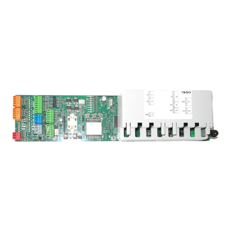
FAAC TM XA R 433 User manual

TM XA R 433

1 1
ENGLISH
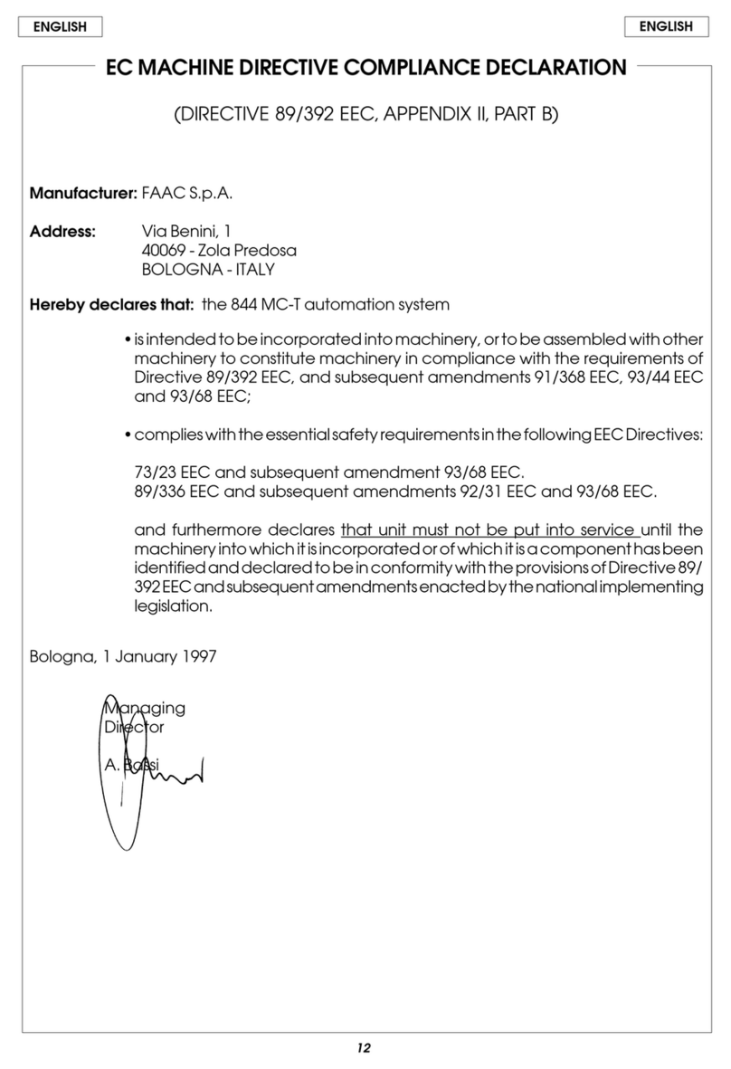
CE CONFORMITY DECLARATION
Manufacturer: FAAC S.p.A.
Address: Via Calari, 10 - 40069 Zola Predosa BOLOGNA - ITALY
Declares that: The control unit
• ·conforms to the essential safety requirements of the following EEC directives
2006/95/EC Low Voltage Directive
99/5/EC R&TTE
CE 0470
Additional note:
This product underwent tests in a typical homogenous configuration
(all products manufactured by FAAC S.p.A.).
Bologna, 01 January 2010
The Managing Director
A.Marcellan
1) ATTENTION! To ensure the safety of people, it is important that
you read all the following instructions. Incorrect installation
or incorrect use of the product could cause serious harm
to people.
2) Read the instructions carefully before installing the product.
3) Do not leave packing materials (plastic, polystyrene, etc.) within
reach of children as such materials are potential sources of
danger.
4) Store these instructions for future reference.
5) This product was designed and built strictly for the use indicated
in this documentation. Any other use, not expressly indicated
here, could compromise the good condition/operation of
the product and/or be a source of danger.
6) FAAC declines all liability caused by improper use or use other
than that for which the automated system was intended.
7) Do not install the equipment in an explosive atmosphere: the
presence of inflammable gas or fumes is a serious danger
to safety.
8) FAAC is not responsible for failure to observe Good Technique
in the construction of the closing elements to be motorised,
or for any deformation that may occur during use.
9) Before attempting any job on the system, cut out electrical
power.
10) The mains power supply of the automated system must be
fitted with an all-pole switch with contact opening distance
of 3mm or greater. Use of a 6A thermal breaker with all-pole
circuit break is recommended.
11) Make sure that a differential switch with threshold of 0.03 A is
fitted upstream of the system.
12) Make sure that the earthing system is perfectly constructed,
and connect metal parts of the means of the closure to it.
13) The safety devices (EN 12978 standard) protect any danger
areas against mechanical movement Risks, such as
crushing, dragging, and shearing.
14) Use of at least one indicator-light (e. g.: FAACLIGHT) is
recommended for every system, as well as a warning sign
adequately secured to the frame structure, in addition to
the devices mentioned at point “15”. (if any)
15) FAAC declines all liability as concerns safety and efficient
operation of the automated system, if system components
not produced by FAAC are used.
16) For maintenance, strictly use original parts by FAAC.
17) Do not in any way modify the components of the automated
system.
18) Do not allow children or adults to stay near the product while
it is operating.
19) Keep radio controls or other pulse generators away from
children, to prevent the automated system from being
activated involuntarily.
20) Transit is only possible when the automated system is idle.
21) The End-user must avoid any attempt to repair or adjust the
automated system personally. These operations must be
carried out exclusively by qualified personnel.
22) Maintenance: perform at least every six months a functional
check of the system, paying special attention to the efficiency
ofthesafety devices(included,whereforeseen, theoperator’s
thrust force) and of the release devices.
23) What is not explicitly stated in these instructions is not
permitted.
IMPORTANT NOTICE FOR THE INSTALLER
GENERAL SAFETY REGULATIONS

2
2 3
72
90
182
ENGLISH
TM XA R 433 (RADIO ANEMOMETER WITH SUN SENSOR)
1 DESCRIPTION AND DIMENSIONS
SUN
SENSOR
WIND
SENSOR
ELECTRICAL
CONNECTIONS

The anemometer TM XA R is a radio-communication device, fed with 230 V.
This device operates in two modes:
1) STANDARD MODE (i.e. for sun blinds; factory default):
The anemometer commands the up operation of the rolling shutter if strong wind or low light are present and the
down operation in the presence of light.
2) REVERSE MODE (i.e. for rolling shutters; can be activated according to chapter 5)
The anemometer commands the down operation of the rolling shutter if wind or low light are present and the up
operation in the presence of light.
Fig.1
Power supply
230 V ~
50/60 Hz
Transmission frequency 433.72 Mhz
Light sensor sensitivity 0,200 ÷ 50
Klux
Wind sensor sensitivity 5 ÷ 60
Km/h
Use temperature -20 ÷ +55
°C
Protection class IP 55
The wind sensor can never be disactivated since it is a protection device for the rolling shutter
when strong wind is present. Its sensitivity can be adjusted through trimmers.
The sun sensor, (from the factory is OFF) , can be activated and disactivated using a dedicated
remote control (i.e. TM XT1S 433 , TM XT6S 433 ). If the sensor is off, the remote controls stored in
the motor memory can command the rolling shutter. If the sensor is active, the remote controls
stored in the memory motor are inhibited: the motor can only be controlled by the TM XA R 433
2 FASTENING AND ELECTRIC WIRING
Dimensions in mm
Fig.2
NEVER SECURE THE SUN SENSOR DIRECTED DOWNWARD

2
2 3
bc
d
a
a
ENGLISH
1) Remove both side screw covers (Fig.4 ref. a)
2) Remove the front cover after having removed the four
screw covers and the screws (Fig.5 ref. b)
3) Move the anemometer cable in order to have the
securing hole free. (Fig.5 ref. c)
4) Drill three securing holes for the anemometer on the wall
in correspondence with its holes (Fig.5 ref. d).
5) Secure the anemometer to the wall using relevant
screws and/or dowels.
6) Place again the anemometer cable in its correct seat (Fig.6 ref. e)
7) Drill the cable bushing (Fig. 6 ref. f), and lead the power cable to the terminals of the anemometer passing through
this hole (Fig.6 ref. g)
8) Be careful to place the rubber cable gland in its seat (Fig.6 ref. h)
9) Fit the cable tie supplied.
10) Turn the anemometer until reaching the desired angle (Fig.4 ref. i)
11) Tighten both side fastening screws and fit the covers (Fig.4 ref. j )
Fig.3
2.1 STANDARD FASTENING
Fig.4
Fig.5

4
4 5
230 V ~
N
L
e
f
h
i
g
j
ENGLISH
2.2 ALTERNATIVE FASTENING OPERATION
1) According to figure 8 ref. a, remove the covers and unscrew the fastening screws.
2) Turn upward the part bin figure 8, keeping the four cover closing screws directed to the sun sensor.
3) Join both parts of the anemometer, select the desired angle and fit the two fastening screws but do not tighten
them (Fig. 9 ref. c).
4) Remove the protective cover (Fig.9 ref. e).
5) Move the anemometer cable in order to have the three securing holes free (Fig. 10 ref. f)
6) Drill the securing holes for the anemometer on the wall in correspondence with its holes. (Fig. 10 ref. g)
7) Secure the anemometer to the wall using the relevant screws and/or dowels.
8) Place the anemometer cable in its seat
9) Drill the cable bushing correctly, lead the power cable to the terminals of the anemometer passing through this
hole (Fig. 11 ref. h)
10) Be careful when positioning the rubber cable gland in its seat. (Fig. 11 ref. i )
11) Fit the cable tie supplied
12) Turn the anemometer until reaching the desired angle
13) Tighten both side fastening screws and fit the covers
Fig.6
Fig.7
PLACE THE RUBBER CABLE
GLAND CORRECTLY

4
4 5
a
a
b
d
c
c
e
f
g
ENGLISH
Fig.8
Fig.9
Fig.10

6
6 7
X 1
PX 1
ON
X 2
NEW
230 V ~
h
i
12 3
45
ENGLISH
3 MEMORY-STORING THE ANEMOMETER ON THE MOTOR
WITHIN 5 SECONDS
WITHIN 5 SECONDS
2 SECONDS
Fig.11
PLACE THE RUBBER CABLE GLAND
CORRECTLY
PRESS BOTH TEST PUSH-BUTTONS
WITHIN 10
SECONDS
1) Supply power to the motor.
2) On an already memory-stored remote control press, within 10 seconds, the programming push-button for 2
seconds.
3) Within 5 seconds press the STOP/PREFERRED POSITION push-button on the same remote control
4) Within 5 seconds, simultaneously press both test push-buttons on the anemometer to be added. (The anemometer
shall be supplied with power)
5) The motor performs two brief movements in both directions to confirm the memory storage.
6) Press one of the two TEST push-buttons to check the up movement of the rolling shutter (to carry out the TEST, the
limit switches must be set)

6
6 7
+
-
+
-
+
-
+
-
6
ENGLISH
4 OPERATION IN STANDARD MODE (factory default)
Radio communication test push-buttons. Pressing one of these
push-buttons, the up movement of the rolling shutter is commanded
and the communication to the associated motor is checked.
Sun sensor activation sensitivity adjustment trimmer:
if you turn it clockwise, the anemometer sends the
commands with higher light intensity
The anemometer commands the up movement of the rolling shutter when strong wind or low light are present, and
its down movement if light increases (if wind is present, the down movement is inhibited)
After the wind sensor operation, the motor does not accept any command for 15 minutes. At the end of this time,
if there is no wind and light is present, the anemometer commands again a down movement of the rolling shutter.
Wind sensor activation sensitivity adjustment
trimmer: if you turn it clockwise, the anemometer
sends the command with higher wind intensity.
If you turn the trimmer clockwise, the rolling shutter goes up with higher light intensity and goes down with
the same light intensity.
If you turn the trimmer counter-clockwise, the rolling shutter goes up with lower light intensity and goes down with
the same light intensity.
MORNING
EVENING
EVENING
MORNING
SUN BLIND OPEN
PRESS ONE OF THE TWO TEST RADIO
COMMUNICATION PUSH-BUTTONS
(same function)
NIGHT
NIGHT
4.1 SUN SENSOR ADJUSTMENT
Fig.17
Fig.18
Fig.19

8
8 9
X 1
PX 1
X 2
+
-
+
-
1
2
3
4
ENGLISH
2 SECONDS
WITHIN 5 SECONDS
WITHIN 5 SECONDS
5 OPERATION IN REVERSE MODE
If you turn the trimmer clockwise, the up movement of the rolling shutter is only commanded if there is a higher
wind intensity. When wind intensity decreases and light is present, the rolling shutter goes down.
If you turn the trimmer counter-clockwise, the up movement of the rolling shutter is only commanded if there is
a lower wind intensity. When wind intensity decreases and light is present, the rolling shutter goes down.
4.2 WIND SENSOR ADJUSTMENT
ANEMOMETER ALREADY STORED IN THE MEMORY
Fig.20
Fig.21
PRESS BOTH PUSH-BUTTONS
AFTER
15 MINUTES
AFTER
15 MINUTES
To activate the reverse operating mode, you need to perform again the memory-storage of the anemometer on the
motor. The anemometer commands the down movement of the rolling shutter if strong wind and low light are present
and its up movement in the event of a light increase.
After the operation of the wind sensor, the motor does not accept any commands for 15 minutes. At the end of this time,
if there is no wind and light is present, the anemometer commands again the up movement of the rolling shutter.
After having memory stored the anemometer on the motor, perform the following operations:
1) Press the programming push-button for 2 seconds on an already memory-stored remote control.
2) Within 5 seconds press on the same remote control the STOP / PREFERRED POSITION push-button
3) Within 5 seconds press simultaneously both test push-buttons on the anemometer.
4) The motor performs two brief movements in both direction to confirm the mode change.
5) Press one of the two TEST push-buttons to check the down movement of the rolling shutter. (to perform the TEST, the
limit switches must be set)
To return to the standard mode perform the same procedure starting from point 1.

8
8 9
+
-
+
-
5
+
-
+
-
ENGLISH
Fig.22
If you turn the trimmer clockwise, the rolling shutter goes down with a higher light intensity and goes up with
the same light intensity.
If you turn the trimmer counter-clockwise, the rolling shutter goes down with low light intensity and goes up with
the same light intensity.
5.2 SUN SENSOR ADJUSTMENT
Fig.23
Fig.24
ROLLING SHUTTER OPEN
5.1 FUNCTIONS
ROLLING SHUTTER CLOSED
Wind sensor activation sensitivity adjustment
trimmer: if you turn it clockwise, the anemometer
sends the commands to the associated motor
with a higher wind intensity.
Sun sensor activation sensitivity adjustment trimmer:
if you turn it clockwise, the anemometer sends the
commands to the associated motor with a higher
light intensity.
Radio communication test push-buttons. If you press one of them, the up
movement of the rolling shutter is commanded and the communication
to the associated motor is checked.
PRESS ONE OF THE TWO RADIO
COMMUNICATION TEST PUSH-BUTTONS
(same function)
EVENING NIGHT
MORNING
EVENING NIGHT
MORNING

10
+
-
+
-
X 2
P
X 2
AB
C
E
D
ENGLISH
If you turn the trimmer clockwise, the up movement of the rolling shutter is only commanded with a higher wind
intensity. When wind intensity decreases and light is present, the rolling shutter goes down.
If you turn the trimmer counter-clockwise, the down movement of the rolling shutter is only commanded with a
lower wind intensity. When wind intensity decreases and light is present, the rolling shutter opens again.
Fig.25
Fig.26
6 DELETING THE ANEMOMETER FROM THE MOTOR MEMORY
1) Press twice the programming push-button on an already memory-stored remote control.
2) Press simultaneously both push-buttons on the anemometer.
3) The motor performs a brief movement in both directions to confirm the deletion.
2 SECONDS
A - Model identification code
B - Identification number of the production batch
C - Read the instructions
D - Dispose of according to current rules in force
E - Notified body reference
7 IDENTIFICATION PLATE
AFTER
15 MINUTES
AFTER
15 MINUTES
5.3 WIND SENSOR ADJUSTMENT

Le descrizioni e le illustrazioni del presente manuale non sono impegnative. La FAAC si riserva il diritto, lasciando inal-
terate le caratteristiche essenziali dell’apparecchiatura, di apportare in qualunque momento e senza impegnarsi
ad aggiornare la presente pubblicazione, le modifiche che essa ritiene convenienti per miglioramenti tecnici o per
qualsiasi altra esigenza di carattere costruttivo o commerciale.
The descriptions and illustrations contained in the present manual are not binding. FAAC reserves the right, whilst
leaving the main features of the equipments unaltered, to undertake any modifications it holds necessary for either
technical or commercial reasons, at any time and without revising the present publication.
Les descriptions et les illustrations du présent manuel sont fournies à titre indicatif. FAAC se réserve le droit d’apporter à
tout moment les modifications qu’elle jugera utiles sur ce produit tout en conservant les caractéristiques essentielles,
sans devoir pour autant mettre à jour cette publication.
Die Beschreibungen und Abbildungen in vorliegendem Handbuch sind unverbindlich. FAAC behält sich das Recht
vor, ohne die wesentlichen Eigenschaften dieses Gerätes zu verändern und ohne Verbindlichkeiten in Bezug auf die
Neufassung der vorliegenden Anleitungen, technisch bzw. konstruktiv/kommerziell bedingte Verbesserungen vorzu-
nehmen.
Las descripciones y las ilustraciones de este manual no comportan compromiso alguno. FAAC se reserva el derecho,
dejando inmutadas las características esenciales de los aparatos, de aportar, en cualquier momento y sin compro-
meterse a poner al día la presente publicación, todas las modificaciones que considere oportunas para el perfec-
cionamiento técnico o para cualquier otro tipo de exigencia de carácter constructivo o comercial.
De beschrijvingen in deze handleiding zijn niet bindend. FAAC behoudt zich het recht voor op elk willekeurig moment de
veranderingen aan te brengen die het bedrijf nuttig acht met het oog op technische verbeteringen of alle mogelijke
andere productie- of commerciële eisen, waarbij de fundamentele eigenschappen van de apparaat gehandhaafd
blijven, zonder zich daardoor te verplichten deze publicatie bij te werken.
FAAC S.p.A.
Via Calari, 10
40069 Zola Predosa (BO) - ITALIA
Tel. 0039.051.61724 - Fax. 0039.051.758518
www.faac.it
www.faacgroup.com
732655 - Rev. A
Table of contents
Other FAAC Control Unit manuals
Popular Control Unit manuals by other brands

Cepex
Cepex EXTREME Series Installation and maintenance manual

Legend
Legend T-6800NL installation instructions

Texas Instruments
Texas Instruments TPS53313 user guide

Emerson
Emerson Anderson Greenwood 93 Series Installation and maintenance instructions

Toray
Toray TORAYFIL HFUG-2020AN instruction manual

Digital Equipment
Digital Equipment MM-10 Series Installing and Cabling