Fanvil BW206 Operational manual

Fanvil Product User Manual
IP Phone
Model: BW206
© 2005 Fanvil technology Co,. Ltd
All rights reserved.
This document is supplied by Fanvil Technology Co., Ltd, No part of this document may
be reproduced, republished or retransmitted in any form or by any means whatsoever,
whether electronically or mechanically, including, but not limited to, by way of
photocopying, recording, information recording or through retrieval systems, without
the express written permission of Fanvil Technology Co., Ltd. Fanvil Technology Co., Ltd
reserves the right to revise this document and make changes at any time and without the
obligation to notify any person and/or entity of such revisions and/or changes. Product
specifications contained in this document are subject to change without notice.

2
Safety Notices
Please read the following safety notices before installing or using this phone. They are crucial for the
safe and reliable operation of the device.
Please use the external power supply that is included in the package. Other power supplies may
cause damage to the phone, affect the behavior or induce noise.
Before using the external power supply in the package, please check with home power voltage.
Inaccurate power voltage may cause fire and damage.
Please do not damage the power cord. If power cord or plug is impaired, do not use it, it may
cause fire or electric shock.
The plug-socket combination must be accessible at all times because it serves as the main
disconnecting device.
Do not drop, knock or shake it. Rough handling can break internal circuit boards.
Do not install the device in places where there is direct sunlight. Also do not put the device on
carpets or cushions. It may cause fire or breakdown.
Avoid exposure the phone to high temperature, below 0℃or high humidity. Avoid wetting the
unit with any liquid.
Do not attempt to open it. Non-expert handling of the device could damage it. Consult your
authorized dealer for help, or else it may cause fire, electric shock and breakdown.
Do not use harsh chemicals, cleaning solvents, or strong detergents to clean it. Wipe it with a soft
cloth that has been slightly dampened in a mild soap and water solution.
When lightning, do not touch power plug or phone line, it may cause an electric shock.
Do not install this phone in an ill-ventilated place.
You are in a situation that could cause bodily injury. Before you work on any equipment, be
aware of the hazards involved with electrical circuitry and be familiar with standard practices for
preventing accidents.

3
Table of Content
1. INTRODUCING BW206 VOIP PHONE ......................................................................................................4
1.1. THANK YOU FOR YOUR PURCHASING BW206 ...............................................................................................4
1.2. DELIVERY CONTENT......................................................................................................................................4
PLEASE CHECK WHETHER THE DELIVERY CONTAINS THE FOLLOWING PARTS: ......................4
THE BASE UNIT WITH KEYPAD.......................................................................................................................4
THE HANDSET.......................................................................................................................................................4
THE HANDSET CABLE........................................................................................................................................4
THE POWER SUPPLY...........................................................................................................................................4
THE ETHERNET CABLE .....................................................................................................................................4
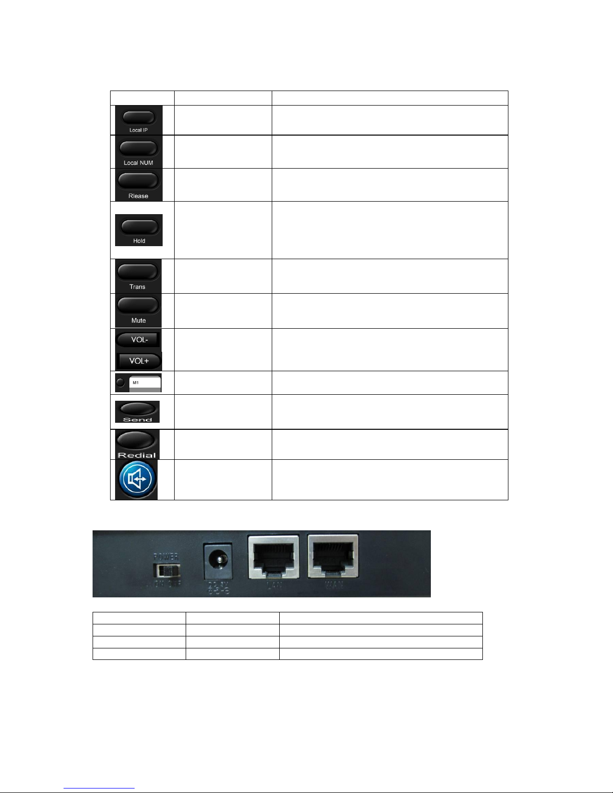
1.3. KEYPAD ..........................................................................................................................................................4
KEY MAPPING:......................................................................................................................................................5
1.4. PORTS FOR CONNECTING ...............................................................................................................................5
2. INITIAL CONNECTING AND SETTING.......................................................................................................6
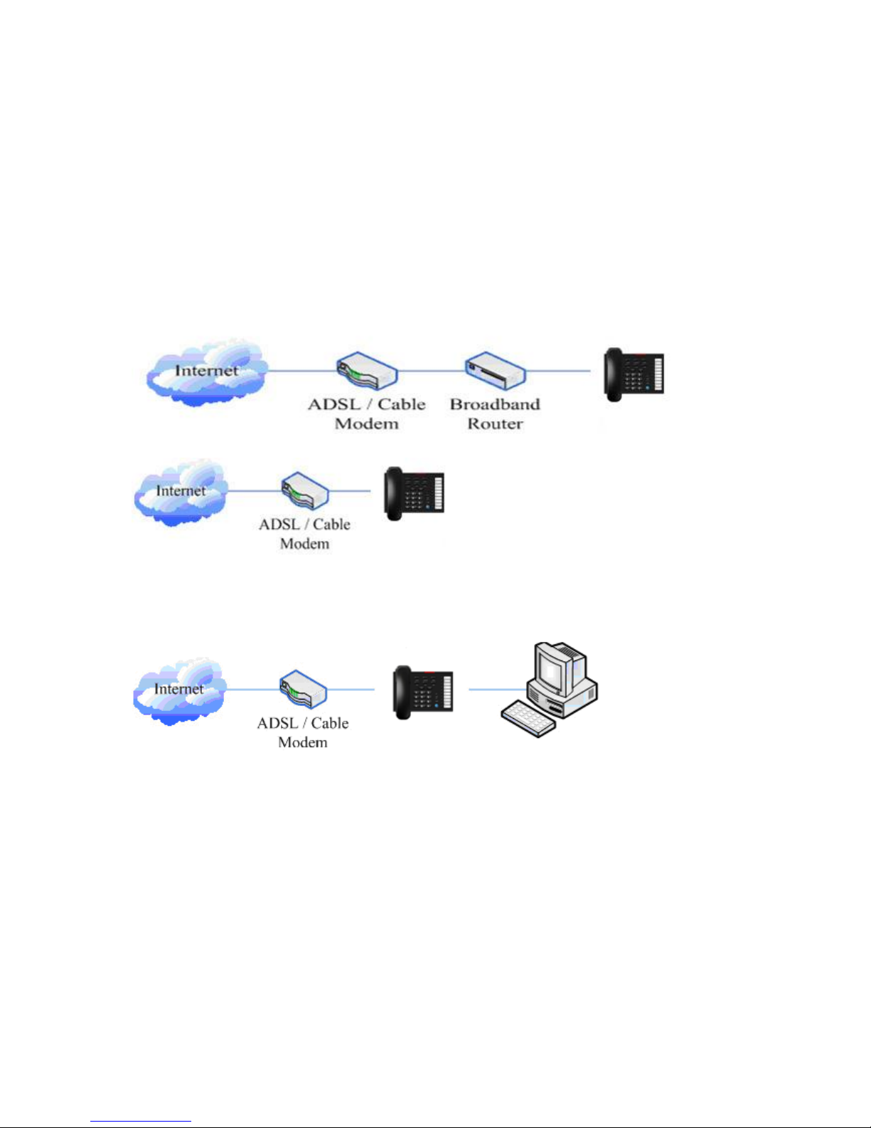
2.1. CONNECT THE PHONE ....................................................................................................................................6
2.2. INITIAL SETTING ............................................................................................................................................7
3. BASIC FUNCTIONS...........................................................................................................................................8
3.1. BASIC OPERATION ..........................................................................................................................................8
3.1.1. Accepting a call.......................................................................................................................................8
3.1.2. Making a call ..........................................................................................................................................8
QUICK-DIALING ............................................................................................................................................8
3.1.3. Ending a call...........................................................................................................................................8
3.1.4. Transferring a call..................................................................................................................................9
3.1.5. Calling Hold and 3 ways call..................................................................................................................9
3.2. THE HIGH-LEVEL OPERATION........................................................................................................................9
3.2.1. Special Keys...........................................................................................................................................10
3.2.2. Call pickup ............................................................................................................................................10
3.2.3. Join call.................................................................................................................................................10
3.2.4. redial/unredial.......................................................................................................................................10
3.2.5. Click to dial...........................................................................................................................................11
4. SETTING............................................................................................................................................................12
4.1. SETTING METHODS.......................................................................................................................................12
4.2. SETTING VIA WEB BROWSE.........................................................................................................................12
4.3. CONFIGURATION VIA WEB..........................................................................................................................13
4.3.1. BASIC ...................................................................................................................................................13
4.3.2. Network .................................................................................................................................................15
4.3.3. VOIP......................................................................................................................................................20
4.3.4. Phone.....................................................................................................................................................27
4.3.5. Maintenance..........................................................................................................................................31
4.3.6. Security..................................................................................................................................................35
4.3.7. Logout ...................................................................................................................................................37
5. APPENDIX.........................................................................................................................................................38
5.1. SPECIFICATION.............................................................................................................................................38

4
1. Introducing BW206 VoIP Phone
1.1. Thank you for your purchasing BW206
Thank you for your purchasing BW206, BW206 is a full-feature telephone that provides voice
communication over the same data network that your computer uses. This phone functions not only much
like a traditional phone, allowing to place and receive calls, and enjoy other features that traditional phone
has, but also it own many data services features which you could not expect from a traditional telephone.
This guide will help you easily use the various features and services available on your phone.
1.2. Delivery Content
Please check whether the delivery contains
the following parts:
The base unit with keypad
The handset
The handset cable
The power supply
The Ethernet cable
1.3. Keypad
The numeric keypad with the keys 0 to 9, *, and #
is used to enterDigits and letters, additionally, the
following keys are available:

5
Key mapping:
Key
Key name
Function Description
Local IP
Press speaker, and then press the key, you would hear
the human voice with phone’s active IP address.
Local Numer
Press speaker, and then press the key, you would hear
the human voice with phone’s SIP phone number.
Release
During talking by handset, pressing the key would let
you close the current call and get new dial tone.
Hold
Temporarily hold the active call during the talking; press
the key again to resume the call. You can also press this
key then input the third party’s phone number and end
with the # key during calling, and then you can make a
call with the third party and hold the previous calling.
Transfer
Use the key to do blind transfer or attended transfer.
Mute
Press this key during talking, you can hear the other
side, but the other side could not hear you.
Volume control
Adjust the ring volume and talking voice volume
Memory key
There are 10 memory keys(or called speed dial keys)
saved 10 number for fast dialing.
Send
Press this key to make a quick dial as soon as you select
your desired number in phone book or callers, or send
the number you dialed manually.
Redial
In the hook off /hands-free mode, use the key to dial the
last call number;
Handfree
Enter into hands-free mode.
1.4. Ports for connecting
POWER
Power switch
Select ON/OFF
DC
Power port
Output: 5V/1.0A
LAN
Network port
Connect it to PC
WAN
Network port
Connect it to Network
The phone has two Network ports: The WAN port and the LAN port. Before you connect the power source,
please carefully read Safety Notices of this user manual.

2. Initial connecting and Setting
2.1. Connect the phone
Step 1: Connect the IP Phone to the corporate IP telephony network. Before you connect the phone to the
network, please check if your network can work normally.
You can do this in one of two ways, depending on how your workspace is set up.
Direct network connection—by this method, you need at least one available Ethernet port in your workspace.
Use the Ethernet cable in the package to connect WAN port on the back of your phone to the Ethernet port in
your workspace. you can make direct network connect. The following two figures are for your reference.
Shared network connection—Use this method if you have a single Ethernet port in your workspace with
your desktop computer already connected to it. First, disconnect the Ethernet cable from the computer and
attach it to the WAN port on the back of your phone. Next, use the Ethernet cable in the package to connect
LAN port on the back of your phone to your desktop computer. Your IP Phone now shares a network
connection with your computer. The following figure is for your reference.
Step 2: Connect the handset to the handset port by the handset cable in the package.
Step 3: connect the power supply plug to the DC port on the back of the phone. Use the power cable to
connect the power supply to a standard power outlet in your workspace.
Step 4: push the on/off switch on the back of the phone to the on side, then the phone’s LED would be lit.
Soon, it would be off until system starts up. Then it would be lit again.
If your VoIP phone registers into corporate IP telephony Server, your phone is ready to use.

2.2. Initial Setting
This VoIP Phone provides you with rich function and parameters setting. If you have enough knowledge
about network and SIP protocol, it is better for you to understand many parameters. But if you know little
about network and SIP protocol, you can also easily make initial setting according to the following steps to
enjoy rapidly high quality voice and low cost from this VoIP Phone.
Before make initial setting, please check if your corporate IP telephony network can work normally, and you
have finished “connect the phone”.
This VoIP Phone Supports DHCP by default. It will receive an IP address and other network-related settings
(Netmask, IP gateway, DNS server) from the DHCP server. If your network supports DHCP, you can
connect this VoIP Phone directly to the network. If your network doesn’t support DHCP, you need change
this VoIP Phone’s network connection setting.

3. Basic Functions
3.1. Basic operation
3.1.1. Accepting a call
There are four methods to accept an incoming call:
Pick up handset to accept incoming calls.
Press the button.
If you need switch from a hands-free call to handset, please pick up the handset directly.
If you need switch from a handset call to hands-free, please press the button, and then hang
up the handset.
3.1.2. Making a call
Quick-dialing
In idle mode, input the called number, and press # key or button, phone will dial the call and
use hands-free automatically.
Use handset
Pick up the handset, and you will hear dialing tone right now. Then input the phone number and end by
the # or button. When you hear ringback tone “du, du…” from handset, the call is through. After
talking, hang up the handset to end the call.
Use hands-free
Press the button and you will hear dialing tone at the same time. Then input the phone number
and end by the # or button. When you hear ringback tone “du, du…” from handset, the call is
through. After talking, press button to end the call.
t
Use the Redial key
Please pick up handset or press the key. After you hear dialing tone, please press the
key to dial the last called number. Note: after you reboot the phone, the phone will clear the redial record, so
there is no redial number.
3.1.3. Ending a call
Hangs up by handset on hook
Hangs up by press when in hands-free

9
Hangs up a call in call waiting state.
If you are in call waiting state, you could press # key to hang up the current call, and switch to the other
call to keep talking. Note: Pressing # key will not hang up if there is only one call currently.
3.1.4. Transferring a call
Call transfer has several ways to realize:
1. When A talks to B, B may press the key and dial C phone number. After B talks to C (or B
hear alert from C), B presses the key, then B hangs up, and A will get through to C.
2. When A is talking with B, C calls B, B may press the key to hold A, and talk to C. Then B
presses the key, A will get through to C.
3. When A talks to B, B presses the key, dial C phone number and # key, then hang up and A
will get through to C.
1 and 2 are attended transfer; 3 is blind transfer.
Notice to VoIP Phone Carrier: Your VoIP phone server need support FRC3515, or else transferring can not
work.
3.1.5. Calling Hold and 3 ways call
There are two modes to enjoy hold function:
1. Press the key during a call, and the call will be on hold. While a call is on hold, you can
establish another call by dialing your desired number and confirm it by the # button. Pressing the
key again you will resume the first call. By using hold function, you can talk with only one
party; the other party who is on hold can’t talk with you. If you press the * button, you will enter into 3
ways call.
2. If the third party calls you during a call, the top led would blink and the phone would paly call waiting
tone. Press the key to hold the first call, and then you can talk with the third party. By using
hold function, you can talk with only one party; the other party who is on hold can’t talk with you. If you
press # key, phone will hang up the first call, and then accept the new incoming call.
Notice: You must enable the calling waiting, or else calling hold can’t work.
3.2. The high-level operation
This VoIP Phone provides more advanced functions after setting at the permission scope of SIP server.

10
3.2.1. Special Keys
Realize Secondary Dial by Dialing for only one time
When you make secondary dial in off-hook/handsfree mode, press key to postpone
input. One hold(--) stands for 2 seconds. For example, you input 123--45, the phone will send
DTMF(45) 2 seconds after the phone call 123. 123------45 will make phone send DTMF(45) at
6 seconds interval.
3.2.2. Call pickup
Call pickup is implemented by simulating pickup function of PBX. it’s that, when A calls B, B rings but no
answer, at this moment, C can hook off and input an appointed prefix plus B’s number, pick up A’s call and
talk with A
The following chart shows how to configure an appointed prefix in dial peer to have call pick up function.
*1* means appointed prefix code. After making the above configuration, C can dial *1* plus the phone
number of B to pick up A’s call. User can set prefix in random, in the case of no affecting current dialing
rules.
3.2.3. Join call
When B is calling C, A can join in the existing call by inputting an appointed prefix numbers plus B or C
number, if B or C also supports join call
The following chart shows how to configure an appointed prefix in dialpeer to have join call function.
*2* means appointed prefix code. After making the above configuration, A can dial *2* plus B or C number
to join B and C’s call. User can set prefix in random, in the case of no affecting current dialing rules.
3.2.4. redial/unredial
If B is in busy line when A calls B, A will get notice: busy, please hang up. If A wants to connect B as soon
as B is in idle, he can use redial function at the moment and he can dials an appointed prefix number plus B’s
number to realize redial function.
What is redial function? A can’t not build a call with B when B is in busy, then A will subscribe B’s calling
mode at 60 second intervals. Once B is available, A will get reminder of rings to hook off, while A hooks off,
A will call B automatically. If at this time A is occupied temporarily and unwilling to contact B, A also can
cancel the redial function by dialing an appointed prefix plus B’s number before making the redial function.
*3* is appointed prefix code. After making the above configuration, A can dial
*3* plus B’s phone number to make the redial function.
*4* is appointed prefix code. After configuration, A can dial *4* to cancel redial function.
User can set prefix in random, in the case of no affecting current dialing rules.

11
3.2.5. Click to dial
When user A browses in an appointed Web page, user A can click to call user B via a link (this link to user
B), then user A’s phone will ring, after A hooks off, the phone will dial to B.

4. Setting
4.1. Setting methods
VoIP Phone is different from the traditional phone; it need be set to make it active. If your VoIP service
provider asks you to set this phone, you can do it easily according to the following methods.
This VoIP Phone can be set via three different setting methods:
The web browser on PC
Telnet
This part will tell you about the setting methods via the web browser on PC.
4.2. Setting via Web Browse
When this phone and your PC are connected to your network, enter the IP address of the wan port in this
phone as the URL (e.g. http://xxx.xxx.xxx.xxx/ or http://xxx.xxx.xxx.xxx:xxxx/).
If you do not know the IP address, you can look it up by IVR of Local IP inquiry.
After you enter the IP address, you will see the following web interface.
This phone provides different two privileges for different users to set it.
The two privileges are guest and administrator respectively. In guest privilege, user can see but not modify
Register/Proxy Sever Addresses, ports of SIP and advance SIP. In administrator privilege, user can see and
modify all setting parameters.
Default value in guest privilege
Username: guest
Password: guest
Default value in Administrator privilege
Username: admin
Password: admin
Input username and password, click “logon”, and you will enter setting web interface.
There is a selection menu on the left side of the web interface. Click on the desired submenu; the current
settings of this submenu will be displayed in the larger field on the right. You can now modify and store the
values by using mouse and keyboard of your PC. To save the changes, click on the submenu “maintenance”
and then click the “config”button and the “Save” button on the right field.

4.3. Configuration via WEB
4.3.1. BASIC
4.3.1.1. Status
Field name
Explanation
Network
Shows the configuration information on WAN and LAN port,
including the connect mode of WAN port (Static, DHCP, PPPoE),
MAC address, the IP address of WAN port and LAN port, ON or
OFF of DHCP mode of LAN port.
Phone Number
Shows the phone numbers provided by the SIP LINE 1-2 servers.
The last line shows the system version.
4.3.1.2. Wizard
Wizard
Field Name
Explanation
Please select the proper network mode according to the network condition. BW206 provide
three different network settings:
Static: If your ISP server provides you the static IP address, please select this mode, and
then finish Static Mode setting. If you don’t know about parameters of Static Mode
setting, please ask your ISP for them.
DHCP: In this mode, you will get the information from the DHCP server automatically;
need not to input this information artificially.
PPPoE: In this mode, your must input your ADSL account and password.
You can also refer to Network setting to speed setting your network.
Choose Static IP MODE,click【NEXT】can config the network and SIP(default SIP1)easily,
also can browse them too. Click【BACK】can return to the last page.

14
Static IP Address
Input the IP address distributed to you.
Netmask
Input the Netmask distributed to you.
Gateway
Input the Gateway address distributed to you.
DNS Domain
Set DNS domain postfix. When the domain which you inputted can
not be parsed, phone will automatically add this domain to the end
of the domain which you inputted before and parse it again.
Primary DNS
Input your primary DNS server address.
Alter DNS
Input your standby DNS server address.
Display Name
If user set the display name, callee will show this display name.
Server Address
Input your SIP server address.
Server Port
Set your SIP server port.
User Name
Input your SIP register account name.
Password
Input your SIP register password.
Phone Number
Input the phone number assigned by your VOIP service provider.
Enable Register
Start to register or not by selecting it or not.
Display detailed information that you manual config.
Choose DHCP MODE,click【NEXT】to config simple SIP(default SIP1). You can browse it
too. Click【BACK】to return to the last page. Like Static IP MODE。
Choose PPPoE MODE,click【NEXT】to config the PPPoE account/password and SIP(default
SIP1). You can browse it too. Click【BACK】to return to the last page. Like Static IP MODE。
PPPoE Server
It will be provided by ISP.
Username
Input your ADSL account.

15
Password
Input your ADSL password.
Notice: Click【Finish】button after finish your setting, IP Phone will save the setting
automatically and reboot.After reboot, you can dial by the SIP account.
4.3.1.3. Call Log
You can look up all the outgoing calls through this page.
Call Log
Field name
explanation
Start Time
Display the start time of the outgoing call
Last Time
Display the conversation time of the outgoing call.
Called Number
Display the account/protocol/line of the outgoing call.
4.3.1.4. MMI SET
MMI SET
Field name
explanation
Language Set
Set the language of phone, English is default.
4.3.2. Network
4.3.2.1. WAN Config
WAN Config
Field Name
explanation

16
Active IP
The current IP address of the phone.
Current Netmask
The current Netmask address.
MAC Address
The current MAC address of the phone.
Current Gateway
The current Gateway IP address.
Get MAC Time
Shows the time of getting MAC address
Please select the proper network mode according to the network condition. FV6030 provide
three different network settings:
Static: If your ISP server provides you the static IP address, please select this mode, and
then finish Static Mode setting. If you don’t know about parameters of Static Mode
setting, please ask your ISP for them.
DHCP: In this mode, you will get the information from the DHCP server automatically;
need not to input this information artificially.
PPPoE: In this mode, your must input your ADSL account and password.
You can also refer to 3.2.1 Network setting to speed setting your network.
If you use static mode, you need set it.
IP Address
Input the IP address distributed to you.
Netmask
Input the Netmask distributed to you.
Gateway
Input the Gateway address distributed to you.
DNS Domain
Set DNS domain postfix. When the domain which you inputted can
not be parsed, phone will automatically add this domain to the end
of the domain which you inputted before and parse it again.
Primary DNS
Input your primary DNS server address.
Alter DNS
Input your standby DNS server address.
Select it to use DHCP mode to get DNS address. If you disable it,
you will use static DNS server. The default is enabling it.
If you uses PPPoE mode,you need to make the above setting.
PPPoE Server
It will be provided by ISP.
Username
Input your ADSL account.
Password
Input your ADSL password.
Notice:
1)Click “Apply” button after finished your setting, IP Phone will save the setting automatically
and new setting will take effect.
2)If you modify IP address, the web will not response by the old IP address. Your need input
new IP address in the address column to logon in the phone.
3)If networks ID which is distributed by DHCP server is same as network ID which is used by
LAN of system, phone will use the DHCP IP to set WAN, and modify LAN’s networks
ID(for example, system will change LAN IP from 192.168.10.1 to 192.168.11.1) when
phone uses DHCP client to get IP in startup; if phone uses DHCP client to get IP in running

17
status and network ID is also same as LAN’s, phone will refuse to accept the IP to configure
WAN.
4.3.2.2. QoS Config
The VOIP phone support 802.1Q/P protocol and DiffServ configuration. VLAN functionality can use
different VLAN IDs by setting signal/voice VLAN and data VLAN. The VLAN application of this phone is
very flexible.
In chart 1, there is a layer 2 switches without setting VLAN. Any broadcast frame will be transmitted to the
other ports except the send port. For example, a broadcast information is sent out from port 1 then
transmitted to port 2,3and 4.
In chart 2, red and blue indicate two different VLANs in the switch, and port 1 and port 2 belong to red
VLAN, port 3 and port 4 belong to blue VLAN. If a broadcast frame is sent out from port 1, switch will
transmit it to port 2, the other port in the red VLAN and not transmit it to port3 and port 4 in blue VLAN. By
this means, VLAN divide the broadcast domain via restricting the range of broadcast frame transmition.
Note: chart 2 use red and blue to identify the different VLAN, but in practice, VLAN uses different VLAN
IDs to identify.

18
QoS Configuration
Field name
explanation
VLAN Enable
Before select it to enable VLAN, you need enable Bridge mode in
LAN config.
VLAN ID Check Enable
Enable VLAN ID check by selecting it. After enable VLAN ID
check, if VLAN ID of a data package is not the same with the
phone’s or a data package do not have VLAN ID, the data package
will be discarded.
Voice/Data VLAN
differentiated
After enable VLAN, system will set packets with different type of
VLAN ID. Undifferentiated means after using VLAN, both VoIP
packets and other data packets will use the voice VLAN ID; tag
differentiated means after using VLAN, VoIP(signal and voice)
packets will add voice VLAN ID, and other data packets will add
data VLAN ID; data untagged means after using VLAN, only VoIP
packets will add voice VLAN ID. Other data packets will not use
VLAN.
DiffServ Enable
Select it or not to Enable or disable DiffServ.
DiffServ Value
Set DiffServ value, the common value is 0x00.
Voice 802.1P Priority
Specify 802.1P Priority of voice/signal data package.
Data 802.1P Priority
Set 802.1p of data VLAN. Non-VoIP data (such as http, telnet, ping
etc) will use this value to set VLAN package.
Voice VLAN ID
Set VLAN ID of voice/signal data package.
Data VLAN ID
Set 802.1q of data VLAN ID. Non-VoIP data (such as http, telnet,
ping etc) will use this value to set VLAN package.
NOTICE:
1)Startup VLAN, if set Voice/Data VLAN differentiated as Undifferentiated, all packets will
use the Voice VLAN ID as the tag.
2) Startup VLAN, if set Voice/Data VLAN differentiated as tag differentiated and disables the
DiffServ, then system will not distinguish the voice and data, all packets will use the Voice
VLAN ID as the tag.
3) Startup VLAN, if set Voice/Data VLAN differentiated as tag differentiated and enables the
DiffServ, then system will distinguish the voice and data and add the VLAN ID each other.
4) Startup VLAN, if set Voice/Data VLAN differentiated as data untagged, then the packet of
the signal/voice will use the Voice VLAN ID as the tag, but the data packets will not take
the VLAN tag.
5) If Disable the VLAN, regardless to set the Voice/Data VLAN differentiated or not, all
packets will not take the VLAN tag; If enable the DiffServ, all packets will only take the
DiffServ value.
6) user need notice, enable the VLAN ID Check Enable that is default, If enable it, the phone
will match the VLAN ID strictly. When others' VLAN ID doesn’t match with us, the

19
packets will discard. Contrarily, the phone will accept the packets with the distinct VLAN
ID.
7) You must gain the IP with the Static mode when you set VLAN, otherwise can't gain the IP
in the VLAN and also can not dial with point to point.
4.3.2.3. Service Port
You can set the port of telnet/HTTP/RTP by this page.
SERVICE PORT
Field name
explanation
HTTP Port
set web browse port, the default is 80 port,if you want to enhance
system safety,you'd better change it into non-80 standard port;
Example: The IP address is 192.168.1.70. and the port value is
8090, the accessing address is http://192.168.1.70:8090
Telnet Port
Set Telnet Port, the default is 23. You can change the value into
others.
Example:
The IP address is 192.168.1.70. the telnet port value is 8023, the
accessing address is telnet 192.168.1.70 8023
RTP Initial Port
Set the RTP Initial Port. It is dynamic allocation.
RTP Port Quantity
Set the maximum quantity of RTP Port, the default is 200.
Notice:
1)You need save the configuration and reboot the phone after set this page.
2)If you modify the port of Telnet and HTTP, you would better set the value more than 1024
because the port value less than 1024 is system port reserved.
3)if you set 0 for the HTTP port, it will disable HTTP service.
4.3.2.4. SNTP
Setting time zone and SNTP (Simple Network Time Protocol) server according to your location, you can
also manually adjust date and time in this web page.

20
SNTP
Field name
explanation
Server
Set SNTP Server IP address.
Time Zone
Select the Time zone according to your location.
Time Out
Set the time out, the default is 60 seconds.
12 Hours Systems
Switch the time mechanism between 12 hours and 24 hours.
Default is 24 hours mode
SNTP
Select the SNTP, and click Apply to make the SNTP Times
effective.
Enable Daylight
Enable daylight saving time
Time shift(minutes)
Setup the variety length
Month
Setup stat and end month
Week
Setup start and end week
Day
Setup start and end day
Hour
Setup start and end hours
Minute
Setup start and end minutes
Notice: You need specify the above all items.
4.3.3. VOIP
4.3.3.1. SIP Config
Set your SIP server in the following interface.
Table of contents
Other Fanvil IP Phone manuals