manuals.online logo
Brands
  1. Home
  2. •
  3. Brands
  4. •
  5. FARFISA INTERCOMS
  6. •
  7. Intercom System
  8. •
  9. FARFISA INTERCOMS MAS22S User manual

FARFISA INTERCOMS MAS22S User manual

Mi 2317/1 1
ITALIANOENGLISHFRANÇAISESPAÑOLPORTUGUÊSDEUTSCH
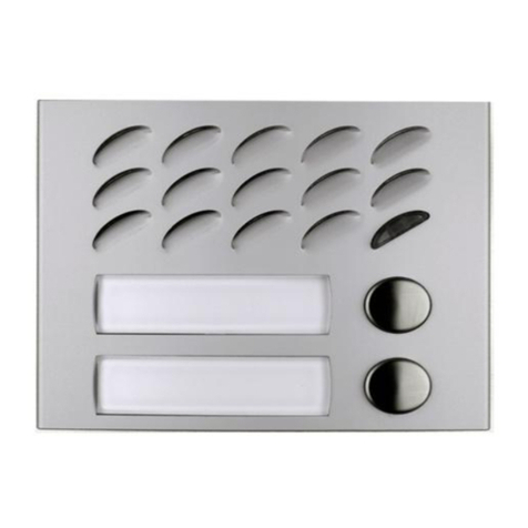
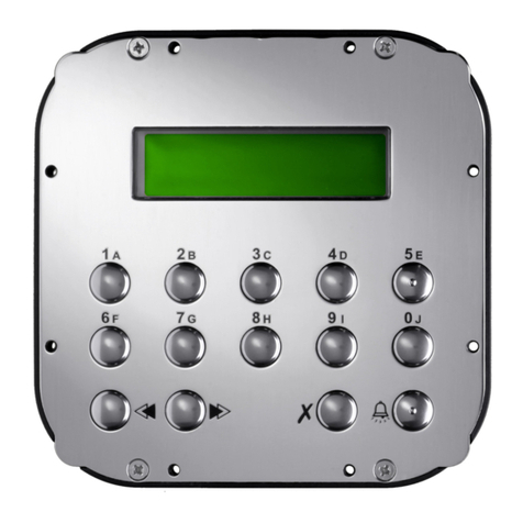
MODULI PULSANTI SERIE
MATRIX CON DECODIFICA IN-
TEGRATA PER SISTEMI DIGI-
TALI
Tramiteilcollegamentoconunopportu-
no codificatore digitale permette di in-
viare chiamate nei sistemi digitali
Farfisa.
Morsetti
Aingresso tensione alternata o conti-
nuaperLedillumina-cartellini(13Vca-
cc)
ingresso tensione alternata o massa
perLed illumina-cartellini
Art. MAS22S
E
MÓDULOS PULSADORES
SERIE MATRIX CON DESCO-
DIFICACIÓN INTEGRADA
PARA SISTEMAS DIGITALES
Una vez conectados a través de un
adecuado codificador digital permiten
enviar llamadas a los sistemas digitales
Farfisa.
Bornes
Aentrada tensión alterna o continua
para los LEDs que iluminan los
tarjeteros (13Vca-cc)
entrada tensión alterna o masa para
los LEDs que iluminan los tarjeteros
MATRIX PUSH-BUTTON
MODULES WITH INTEGRA-
TED ENDECODING BOARD
FOR DIGITAL SYSTEMS
Connected with a digital encoder the
modules allow to send calls in Farfisa
digital systems.
Terminals
AAC or DC power supply input for
name-plate Led (13Vac or dc)
AC power supply or ground input for
name-plate Led
MODULES BOUTONS-
POUSSOIRS SÉRIE MATRIX
AVEC DÉCODAGE INTÉGRÉ
POUR SYSTÈMES DIGITAUX
Laconnexionà un codeur digital prévu à
cet effet permet d’adresser des appels
dans les systèmes digitaux Farfisa.
Bornes
Aentrée courant alternatif ou continu
pour Led rétro-éclairage étiquettes
porte-noms (13Vca-cc)
entrée courant alternatif ou o masse
pour Led rétro-éclairage étiquettes
porte-noms
MÓDULOS DE BOTÕES
SÉRIE MATRIX COM DECODI-
FICAÇÃO INTEGRADA PARA
SISTEMAS DIGITAIS
Através da coligação com um
codificador digital, é possível enviar
chamadasnos sistemas digitaisFarfisa.
Terminais
Aingresso tensão alternada para Led
ilumina-cartõezinhos(13Vca-cc)
ingressotensão alternada ou massa
paraLed ilumina-cartõezinhos
TASTENMODULE DER
SERIE MATRIX MIT EINGE-
BAUTEM DECODER FÜR
DIGITALSYSTEME
Bei Verbindung mit einem Digital-
Codec können Rufe in den Farfisa-
Digital-systemenweitergeleitet werden.
Klemmen
AWechsel-oderGleichstrom-Eingang
für LED zur Namensschilder-
beleuchtung (13V Gs/Ws)
Wechsel- oder Masse-Eingang für
LED zur Namensschilder-
beleuchtung
Mi 2317/1
Art. MAS24S
Cod. M527035910
Smaltire il dispositivo secondo quanto prescritto dalle norme per la tutela dell'ambiente.
Dispose of the device in accordance with environmental regulations.
Écouler le dispositif selon tout ce qu'a été prescrit par les règles pour la tutelle du milieu.
Eliminar el aparato según cuánto prescrito por las normas por la tutela del entorno.
Disponha do dispositivo conforme regulamentos ambientais.
Werden Sie das Gerät in Übereinstimmung mit Umweltregulierungen los.
ACI srl Farfisa Intercoms
Via E.Vanoni, 3 • 60027 Osimo (AN)•Italy
Tel: +39 071 7202038 (r.a.)
Fax: +39 071 7202037
e-mail: [email protected]
www.farfisa.com
Mi 2317/1 2
ITALIANOENGLISHFRANÇAISESPAÑOLPORTUGUÊSDEUTSCH
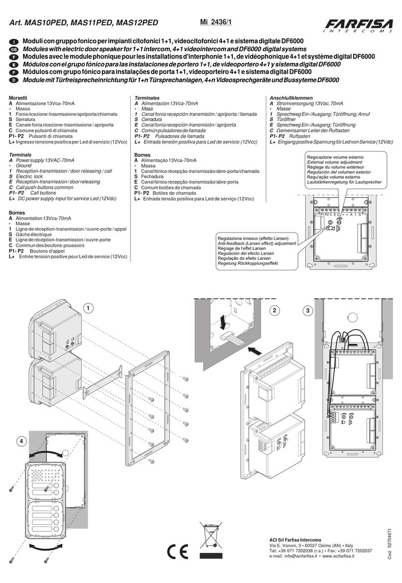
Installazione e collegamenti
- Collegare il modulo codificatore digitale
al connettore JP1 del primo modulo
MAS22S o MAS24S tramite il cavetto
fornito a corredo del codificatore.
- Collegare il connettore JP2 del primo
modulo al JP1 del secondo modulo
MAS22S o MAS24S utilizzando i cavetti
forniti a corredo.
- Collegare di seguito tutti i moduli.
- Rimuovere il cavo dell'ultimo modulo
perchèinutilizzato.
Installation and connections
- Connect the digital encoder to the con-
nector JP1 of the first MAS22S or
MAS24S module using the flat cable
supplied with the digital encoder.
- Connect the connector JP2 of the first
MAS22S or MAS24S module to the
connector JP1 of the second MAS22S or
MAS24S module using the flat cable
supplied with the product.
- Connect in the same way all the other
MAS22S or MAS24S modules.
- Remove the flat cable from the last
MAS22S or MAS24S module because
it is not used.
Installation et branchements
- Brancherle module digital de codage àla
borne JP1 du premier module MAS22S
ou MAS24S par le biais du câble fourni
avec le module même.
- Brancherlaborne JP2 dupremiermodule
à celle JP1 du second module MAS22S
ouMAS24S en utilisantlescâbles fournis.
- Brancher à la suite tous les modules.
- Enlever le câble du dernier module car
inutilisé.
E
Instalación y conexiones
- Conectar el módulo codificador digital al
conectador JP1 del primer módulo
MAS22S ó MAS24S mediante el cable
en dotación del codificador.
- Conectar el conectador JP2 del primer
módulo al JP1 del segundo módulo
MAS22Só MAS24S utilizando los cables
suministrados en dotación.
- Conectar luego todos los módulos.
- Quitar el cable del último módulo porque
no se va a ocupar.
aaaaaaaaaaaaaaaaaaaaaaaaaaaaaaa
a
aaaaaaaaaaaaaaaaaaaaaaaaaaaaa
a
a
aaaaaaaaaaaaaaaaaaaaaaaaaaaaa
a
a
aaaaaaaaaaaaaaaaaaaaaaaaaaaaa
a
a
aaaaaaaaaaaaaaaaaaaaaaaaaaaaa
a
a
aaaaaaaaaaaaaaaaaaaaaaaaaaaaa
a
a
aaaaaaaaaaaaaaaaaaaaaaaaaaaaa
a
a
aaaaaaaaaaaaaaaaaaaaaaaaaaaaa
a
a
aaaaaaaaaaaaaaaaaaaaaaaaaaaaa
a
a
aaaaaaaaaaaaaaaaaaaaaaaaaaaaa
a
a
aaaaaaaaaaaaaaaaaaaaaaaaaaaaa
a
a
aaaaaaaaaaaaaaaaaaaaaaaaaaaaa
a
a
aaaaaaaaaaaaaaaaaaaaaaaaaaaaa
a
a
aaaaaaaaaaaaaaaaaaaaaaaaaaaaa
a
a
aaaaaaaaaaaaaaaaaaaaaaaaaaaaa
a
a
aaaaaaaaaaaaaaaaaaaaaaaaaaaaa
a
a
aaaaaaaaaaaaaaaaaaaaaaaaaaaaa
a
a
aaaaaaaaaaaaaaaaaaaaaaaaaaaaa
a
a
aaaaaaaaaaaaaaaaaaaaaaaaaaaaa
a
a
aaaaaaaaaaaaaaaaaaaaaaaaaaaaa
a
a
aaaaaaaaaaaaaaaaaaaaaaaaaaaaa
a
a
aaaaaaaaaaaaaaaaaaaaaaaaaaaaa
a
a
aaaaaaaaaaaaaaaaaaaaaaaaaaaaa
a
a
aaaaaaaaaaaaaaaaaaaaaaaaaaaaa
a
a
aaaaaaaaaaaaaaaaaaaaaaaaaaaaa
a
a
aaaaaaaaaaaaaaaaaaaaaaaaaaaaa
a
a
aaaaaaaaaaaaaaaaaaaaaaaaaaaaa
a
a
aaaaaaaaaaaaaaaaaaaaaaaaaaaaa
a
a
aaaaaaaaaaaaaaaaaaaaaaaaaaaaa
a
a
aaaaaaaaaaaaaaaaaaaaaaaaaaaaa
a
a
aaaaaaaaaaaaaaaaaaaaaaaaaaaaa
a
a
aaaaaaaaaaaaaaaaaaaaaaaaaaaaa
a
a
aaaaaaaaaaaaaaaaaaaaaaaaaaaaa
a
a
aaaaaaaaaaaaaaaaaaaaaaaaaaaaa
a
a
aaaaaaaaaaaaaaaaaaaaaaaaaaaaa
a
a
aaaaaaaaaaaaaaaaaaaaaaaaaaaaa
a
a
aaaaaaaaaaaaaaaaaaaaaaaaaaaaa
a
a
aaaaaaaaaaaaaaaaaaaaaaaaaaaaa
a
a
aaaaaaaaaaaaaaaaaaaaaaaaaaaaa
a
a
aaaaaaaaaaaaaaaaaaaaaaaaaaaaa
a
a
aaaaaaaaaaaaaaaaaaaaaaaaaaaaa
a
a
aaaaaaaaaaaaaaaaaaaaaaaaaaaaa
a
a
aaaaaaaaaaaaaaaaaaaaaaaaaaaaa
a
a
aaaaaaaaaaaaaaaaaaaaaaaaaaaaa
a
a
aaaaaaaaaaaaaaaaaaaaaaaaaaaaa
a
a
aaaaaaaaaaaaaaaaaaaaaaaaaaaaa
a
a
aaaaaaaaaaaaaaaaaaaaaaaaaaaaa
a
a
aaaaaaaaaaaaaaaaaaaaaaaaaaaaa
a
aaaaaaaaaaaaaaaaaaaaaaaaaaaaaaa
Instalação e coligações
- Coligar o módulo codificador
digitalao conector JP1doprimeiro
módulo MAS22S ou MAS24S
através do cabinho fornecido na
embalagem do codificador.
- Coligaro conector JP2doprimeiro
módulo ao JP1 do segundo
módulo MAS22S ou MAS24S
utilizando os cabinhos fornecidos
na embalagem.
- Em seguida, coligar todos os
módulos.
- Removerocabodo último módulo
já que inutilizado.
Installation und
Anschlüsse
- Digital-Codec-Modul mit Hilfe des
zusammen mit dem Kodiergerät
gelieferten Kabels an den JP1-
Verbinder des ersten Moduls MAS22S
oder MAS24S anschließen.
- JP2-Verbinder des ersten Moduls an
denJP1-Verbinderdes zweiten Moduls
MAS22S oder MAS24S mit Hilfe der
mitgelieferten Kabel anschließen.
- Im folgenden alle Module
anschließen.
- Kabel des letzten Moduls entfernen,
da es nicht benötigt wird.
Mi 2317/1 3
ITALIANOENGLISHFRANÇAISESPAÑOLPORTUGUÊSDEUTSCH
Programmazione
La programmazione dei microinterruttori, presenti sul retro
dei moduli MAS22S e MAS24S, permette al codificatore
digitale di conoscere la sequenza dei pulsanti ad esso colle-
gati.Talenumerazionedevecorrispondereallacodifica degli
utenti interni. Nei casi di impianti con ingressi secondari
(divisione a scale) occorre fare attenzione anche alla fascia
numerica riconoscibile dallo scambiatore digitale.
Il codice impostato sui microinterruttori equivale all'indirizzo
associato al 1° pulsante partendo dall'alto. I pulsanti succes-
sivi prenderanno automaticamente indirizzi crescenti (es.
programmando il codice dei microinterruttori a 36 i pulsanti,
apartiredall'alto di un modulo MAS24S, chiameranno rispet-
tivamente gli indirizzi 36, 37, 38 e 39).
Nota 1. Fare attenzione a quando si programma il codice 0
(fascia numerica 0-3), ricordarsi infatti che il primo
pulsantedall'altononchiamanessunutente.Questo
avvieneperchèl'impiantodigitalenonriconoscecome
numero di chiamata la cifra 0 (zero).
Nota 2. In caso di utilizzo del modulo MAS22S, che ha 2
pulsanti, gli indirizzi associati al 3° e 4° pulsante
andrannoperduti.
Programmation
Laprogrammation des micro-interrupteurs, présents en face
arrièredesmodulesMAS22S et MAS24S, permet au module
de codage digital de reconnaître la séquence des boutons-
poussoirs qui lui sont reliés. Cette numérotation doit
correspondre au codage des utilisateurs internes. Dans les
installationsayantdesentréessecondaires(division àpaliers),
il faut également faire attention à la plage numérique que
l’échangeur digital est en mesure de reconnaître.
Lecodeprogrammésurlesmicro-interrupteurscorrespondà
l’adresse affectée au 1er bouton-poussoir en partant du haut.
Desadressescroissantes seront automatiquement affectées
aux boutons-poussoirs successifs (par exemple, en
programmant le code des micro-interrupteurs à 36 boutons-
poussoirs, à partir du haut d’un module MAS24S, ils
appelleront respectivement les adresses 36, 37, 38 et 39).
Note 1. Attention lors de la programmation du code 0 (plage
numérique 0-3) : il faut en effet se rappeler que le
premier bouton-poussoir du haut n’appelle aucun
utilisateur. Ceci parce que l’installation digitale ne
reconnaît par le chiffre 0 (zéro) en tant que numéro
d’appel.
Note 2. En cas d’utilisation du module MAS22S, équipé de 2
boutons-poussoirs, les adresses affectées aux 3ème
et 4ème boutons-poussoirs sont sinon perdues.
Programming
The micro-switches, present on the back of the MAS22S or
MAS24S, allow the digital encoder to recognize the code of
the connected buttons, consequently they must be
programmed properly.
The programmed codes must correspond to the addresses
of the internal users. In case of installations with secondary
door stations (multiple entrances), attention must be paid
also to the numerical interval recognized by the digital
exchanger.
The code set on the micro-switches is the address called by
the first button of the module starting from the top. The other
buttons will call increasing addresses ( e.g. if the code set on
the micro-switches is 36 the buttons, starting from the top of
an MAS24S module, will call respectively the users 36, 37,
38 and 39.
Note 1. Great attention must be paid when the code 0
(numerical interval 0-3) is set on the micro-switches
because in this case the first button, starting from the
top of the module MAS22S or MAS24S will call no
users. This is because the digital system does not
recognize the address 0 (zero).
Note 2. In case of the module MAS22S with 2 buttons, the
addresses associated to the 3rd and 4th button will be
lost.
E
Programación
La programación de los micro-interruptores que se
encuentran en la parte posterior de los módulos MAS22S y
MAS24S, permite al codificador digital conocer la secuencia
de los pulsadores conectados al mismo. Esta numeración
debe corresponder a la codificación de los usuarios internos.
En caso de instalaciones con entradas secundarias (división
por escalera) es necesario poner atención también a la
banda numérica que reconoce el intercambiador digital.
El código programado en los micro-interruptores equivale a
la dirección asociada al 1° pulsador desde arriba. Los
pulsadores siguientes tomarán automáticamente
direcciones en aumento (ej. programando el código de los
micro-interruptores a 36 los pulsadores, a partir desde arriba
de un módulo MAS24S, llamarán respectivamente las
direcciones 36, 37, 38 y 39).
Nota 1. Poner atención cuando se va a programar el código
0 (banda numérica 0-3). Hay que recordar que el
primer pulsador arriba no llama ningún usuario.
Esto pasa porque la instalación digital no reconoce
como número de llamada el número 0 (cero).
Nota 2. En caso de uso del módulo MAS22S que tiene 2
pulsadores, las direcciones asociadas al 3° y 4°
pulsador se van a perder.
Mi 2317/1 4
ITALIANOENGLISHFRANÇAISESPAÑOLPORTUGUÊSDEUTSCH
Programação
A programação dos microinterruptores, presentes no retro
dosmódulosMAS22S e MAS24S, possibilitaaocodificador
digital conhecer a sequência dos botões a ele coligados.
Esta numeração deve corresponder à codificação dos
usuáriosinternos.Noscasosdeinstalaçõescomingressos
secundários, (divisão por escadas), é necessário prestar
atenção também à faixa numérica reconhecível pelo
permutador digital.
O código impostado nos microinterruptores equivale ao
endereço associado ao 1º botão partindo do alto. Os
botõessucessivos tomarão, automaticamente, endereços
crescentes (ex.: ao programar o código dos
microinterruptores a 36 botões, a partir do alto de um
módulo MAS24S, chamarão, respectivamente, os
endereços 36, 37, 38 e 39).
Nota 1. Prestar atenção quando for programado o código
0 (faixa numérica 0-3), lembramos, de fato, que o
primeirobotãodoaltonãochamanenhum usuário.
Isto acontece porque a instalação digital não
reconhece como número de chamada o algarismo
0 (zero).
Nota 2. Em caso de utilização do módulo MAS22S, que
possui 2 botões, os endereços associados aos
botões 3° e 4° serão perdidos.
Programmierung
Mit Hilfe der Programmierung der Mikroschalter auf der
Rückseite der Module MAS22S und MAS24S erkennt das
Digital-Codec die Reihenfolge der daran angeschlossenen
Tasten. Diese Nummerierung muss der Kodierung der
internen Teilnehmer entsprechen. Bei Anlagen mit
Nebeneingängen(Treppenunterteilung) muss auch darauf
geachtetwerden, dassderNummernbereich vonderDigital-
Umschalteinrichtung erkannt wird.
Der in den Mikroschaltern eingegebene Code entspricht
der Adresse der ersten Taste von oben. Die nachfolgenden
Tasten erhalten automatisch aufsteigende Adressen (so
werden beispielsweise bei Programmierung der
Mikroschalter mit 36 Tasten von oben angefangen bei
einem Modul MAS24S jeweils die Adressen 36, 37, 38
und 39 angerufen).
Hinweis 1. Bei Programmierung des Codes 0
(Nummernbereich 0-3) ist zu beachten, dass
die erste Taste von oben keinen Teilnehmer
rufen kann. Dies ist dadurch bedingt, dass
die Digitalanlage die Ziffer 0 (null) nicht als
Rufnummer erkennt.
Hinweis 2. Bei Verwendung des Moduls MAS22S mit 2
Tasten gehen die Adressen, die
normalerweiseder3.und4. Tastezugewiesen
sind, verloren.
Fascia numerica Posizione microinterruttori
Numerical interval Microswitch position
Gamme de numéros Position micro-interrupteurs
Franja numérica Posición microinterruptores
Faixa numérica Posição micro-interruptores
Nummerngruppe Mikroschalterposition
0 ÷ 3
4 ÷ 7
8 ÷ 11
12 ÷ 15
16 ÷ 19
20 ÷ 23
24 ÷ 27
28 ÷ 31
32 ÷ 35
36 ÷ 39
40 ÷ 43
44 ÷ 47
48 ÷ 51
52 ÷ 55
56 ÷ 59
60 ÷ 63

This manual suits for next models

1

Other FARFISA INTERCOMS Intercom System manuals

FARFISA INTERCOMS PT 522W User manual

FARFISA INTERCOMS

FARFISA INTERCOMS PT 522W User manual

FARFISA INTERCOMS MD 10D User manual

FARFISA INTERCOMS

FARFISA INTERCOMS MD 10D User manual

FARFISA INTERCOMS TD2100MAS User manual

FARFISA INTERCOMS

FARFISA INTERCOMS TD2100MAS User manual

FARFISA INTERCOMS MAS10PED User manual

FARFISA INTERCOMS

FARFISA INTERCOMS MAS10PED User manual

FARFISA INTERCOMS EX3262 User manual

FARFISA INTERCOMS

FARFISA INTERCOMS EX3262 User manual

FARFISA INTERCOMS ZHERO ZH1262AGLB User manual

FARFISA INTERCOMS

FARFISA INTERCOMS ZHERO ZH1262AGLB User manual

FARFISA INTERCOMS Exhito Series User manual

FARFISA INTERCOMS

FARFISA INTERCOMS Exhito Series User manual

FARFISA INTERCOMS EH9160PLCW User manual

FARFISA INTERCOMS

FARFISA INTERCOMS EH9160PLCW User manual

FARFISA INTERCOMS CD4134PL User manual

FARFISA INTERCOMS

FARFISA INTERCOMS CD4134PL User manual

FARFISA INTERCOMS myLogic PL72 User manual

FARFISA INTERCOMS

FARFISA INTERCOMS myLogic PL72 User manual

FARFISA INTERCOMS Kit 1PEXD User manual

FARFISA INTERCOMS

FARFISA INTERCOMS Kit 1PEXD User manual

FARFISA INTERCOMS TD4100MAS User manual

FARFISA INTERCOMS

FARFISA INTERCOMS TD4100MAS User manual

FARFISA INTERCOMS Agora AG100TS User manual

FARFISA INTERCOMS

FARFISA INTERCOMS Agora AG100TS User manual

FARFISA INTERCOMS ECHOS User manual

FARFISA INTERCOMS

FARFISA INTERCOMS ECHOS User manual

FARFISA INTERCOMS EH9161FPLCW User manual

FARFISA INTERCOMS

FARFISA INTERCOMS EH9161FPLCW User manual

FARFISA INTERCOMS myLogic one ML2002PLC User manual

FARFISA INTERCOMS

FARFISA INTERCOMS myLogic one ML2002PLC User manual

FARFISA INTERCOMS TD4100PL User manual

FARFISA INTERCOMS

FARFISA INTERCOMS TD4100PL User manual

FARFISA INTERCOMS 1PXFED User manual

FARFISA INTERCOMS

FARFISA INTERCOMS 1PXFED User manual

FARFISA INTERCOMS Profilo TD6100PL User manual

FARFISA INTERCOMS

FARFISA INTERCOMS Profilo TD6100PL User manual

FARFISA INTERCOMS Kit 2PEXD User manual

FARFISA INTERCOMS

FARFISA INTERCOMS Kit 2PEXD User manual

FARFISA INTERCOMS ECHOS EH9262AGCT User manual

FARFISA INTERCOMS

FARFISA INTERCOMS ECHOS EH9262AGCT User manual

FARFISA INTERCOMS Compact Profilo KM8111PLCW User manual

FARFISA INTERCOMS

FARFISA INTERCOMS Compact Profilo KM8111PLCW User manual

FARFISA INTERCOMS EX3160PL User manual

FARFISA INTERCOMS

FARFISA INTERCOMS EX3160PL User manual

FARFISA INTERCOMS ZHEROS ZH1252B User manual

FARFISA INTERCOMS

FARFISA INTERCOMS ZHEROS ZH1252B User manual

Popular Intercom System manuals by other brands

Arlo HD Camera plus Audio Doorbell quick start guide

Arlo

Arlo HD Camera plus Audio Doorbell quick start guide

Vimar PIXEL UP 40415.S user manual

Vimar

Vimar PIXEL UP 40415.S user manual

Bticino CLASSE 100X installation manual

Bticino

Bticino CLASSE 100X installation manual

golmar Vista Plus Rock Series instruction manual

golmar

golmar Vista Plus Rock Series instruction manual

David Clark 9800 Series installation manual

David Clark

David Clark 9800 Series installation manual

Cyfral CC-4000 Operating, Installation and Programming Manual

Cyfral

Cyfral CC-4000 Operating, Installation and Programming Manual

Orisec CT-10 user guide

Orisec

Orisec CT-10 user guide

2N IP Vario installation manual

2N

2N IP Vario installation manual

Akuvox R20K Admin guide

Akuvox

Akuvox R20K Admin guide

Chamberlain WIRELESS PORTABLE INDOOR/OUTDOOR INTERCOM... user manual

Chamberlain

Chamberlain WIRELESS PORTABLE INDOOR/OUTDOOR INTERCOM... user manual

Commax CDV-43U user manual

Commax

Commax CDV-43U user manual

Avidsen YLVA 3+ manual

Avidsen

Avidsen YLVA 3+ manual

BASI TS810 Mounting and operating instructions

BASI

BASI TS810 Mounting and operating instructions

Tador TOPAZ user guide

Tador

Tador TOPAZ user guide

Commax CDV-43K user manual

Commax

Commax CDV-43K user manual

Axis A8004-VE installation guide

Axis

Axis A8004-VE installation guide

Anchor AnchorMAN owner's manual

Anchor

Anchor AnchorMAN owner's manual

Vimar ELVOX Pixel Up Series Installation and wiring manual

Vimar

Vimar ELVOX Pixel Up Series Installation and wiring manual

manuals.online logo
manuals.online logoBrands
  • About & Mission
  • Contact us
  • Privacy Policy
  • Terms and Conditions

Copyright 2025 Manuals.Online. All Rights Reserved.