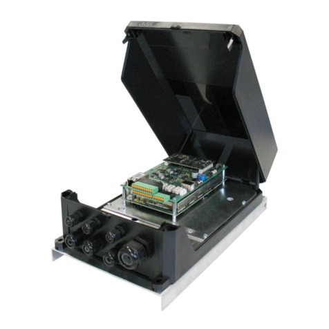
Feig Electronic OBID i-scan ID ISC.LRM2500-B User manual
Other Feig Electronic Control Unit manuals
Feig Electronic
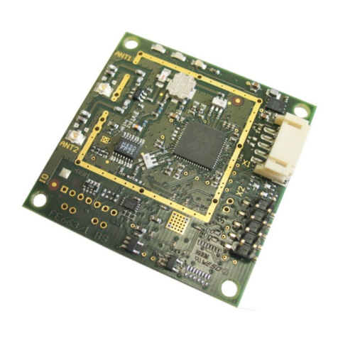
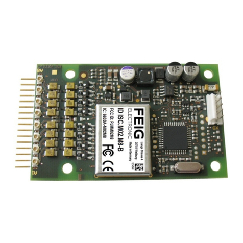
Feig Electronic ID ISC.M02.M8 User manual

Feig Electronic
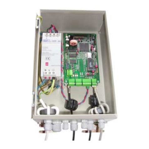
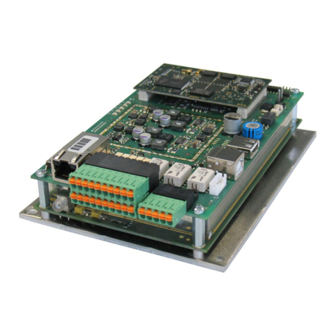
Feig Electronic TST WUI Installation manual
Feig Electronic
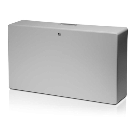
Feig Electronic OBID i-scan ID ISC.LRM2500-B User manual
Feig Electronic
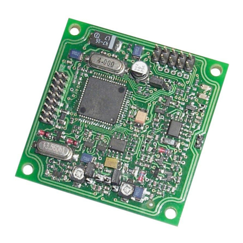
Feig Electronic ID ISC.ANT.U500/270 User manual
Feig Electronic
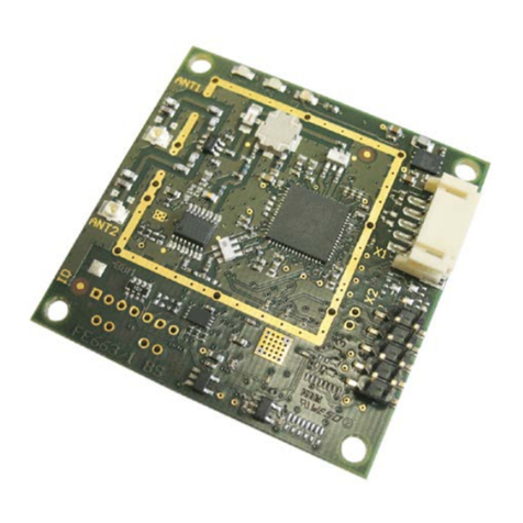
Feig Electronic OBID i-scan ID ISC.M02 User manual
Feig Electronic
Feig Electronic ID ISC.MU02.02-CU User manual
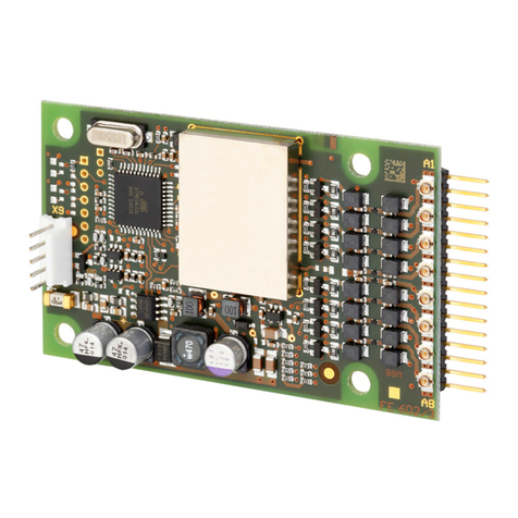
Feig Electronic
Feig Electronic OBID i-scan ID ISC.M02.M8-B User manual
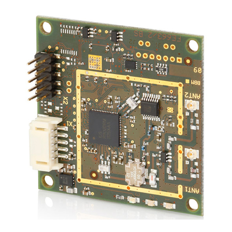
Feig Electronic
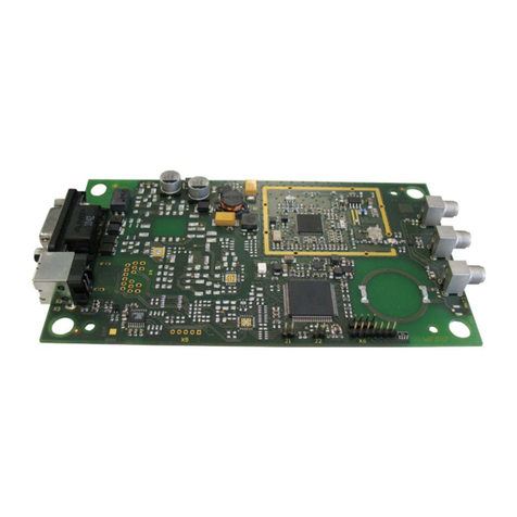
Feig Electronic OBID i-scan D ISC.MU02.02 User manual
Feig Electronic
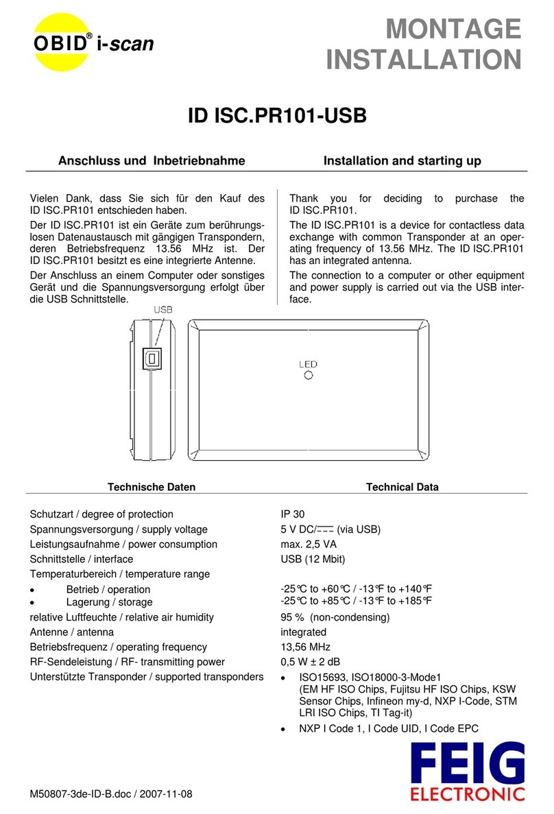
Feig Electronic OBID i-scan ID ISC.PR101-USB User manual
Feig Electronic
Feig Electronic ID ISC.MRMU102-A User manual

Feig Electronic
Feig Electronic OBID i-scan ID ISC.M02 User manual

Feig Electronic
Feig Electronic OBID i-scan ID ISC.M02.M8-B User manual

Feig Electronic
Feig Electronic cVEND plug User manual

Feig Electronic
Feig Electronic OBID i-scan ID ISC.PRH102-B User manual
Feig Electronic
Feig Electronic OBID i-scan ID ISC.MAT-A User manual
Feig Electronic
Feig Electronic OBID i-scan ID ISC.LRM2500-A User manual
Feig Electronic
Feig Electronic ID ISC.MRMU102-A User manual
Feig Electronic
Feig Electronic ID ISC.MRMU102-A User manual

Feig Electronic
Feig Electronic ID ISC.LRM1002-E Use and care manual
Feig Electronic
Feig Electronic ID MAX.U1002 User manual
Popular Control Unit manuals by other brands

Festo
Festo Compact Performance CP-FB6-E Brief description

Elo TouchSystems
Elo TouchSystems DMS-SA19P-EXTME Quick installation guide

JS Automation
JS Automation MPC3034A user manual

JAUDT
JAUDT SW GII 6406 Series Translation of the original operating instructions

Spektrum
Spektrum Air Module System manual

BOC Edwards
BOC Edwards Q Series instruction manual

KHADAS
KHADAS BT Magic quick start

Etherma
Etherma eNEXHO-IL Assembly and operating instructions

PMFoundations
PMFoundations Attenuverter Assembly guide

GEA
GEA VARIVENT Operating instruction

Walther Systemtechnik
Walther Systemtechnik VMS-05 Assembly instructions

Altronix
Altronix LINQ8PD Installation and programming manual
