manuals.online logo
Brands
  1. Home
  2. •
  3. Brands
  4. •
  5. Festo
  6. •
  7. Control Unit
  8. •
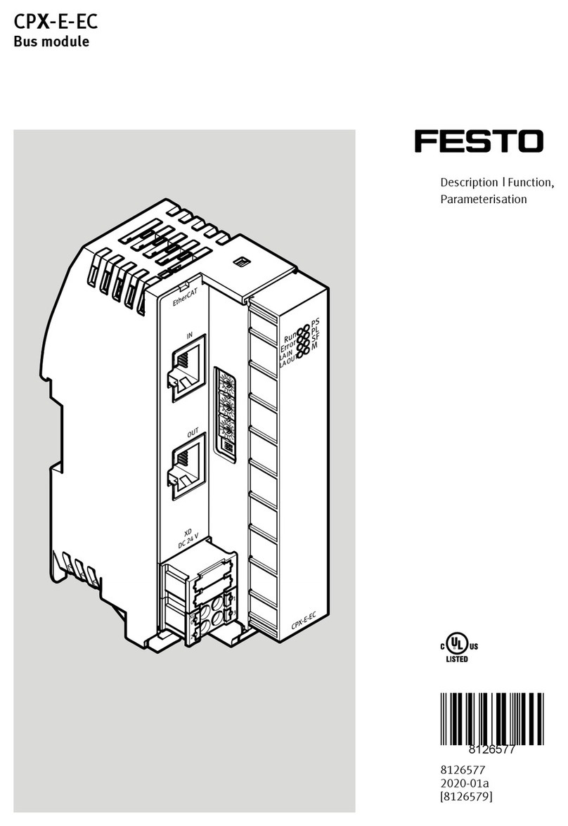
  9. Festo CPX-E-PB User manual

Festo CPX-E-PB User manual

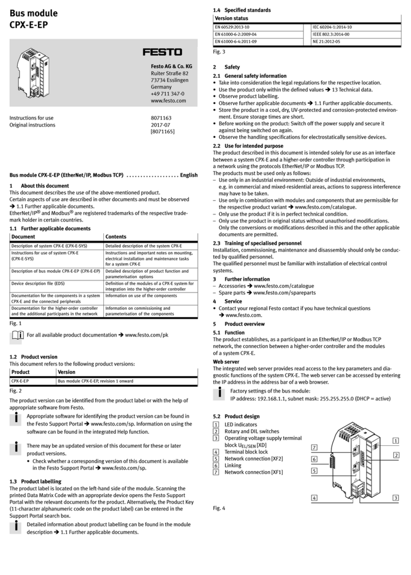
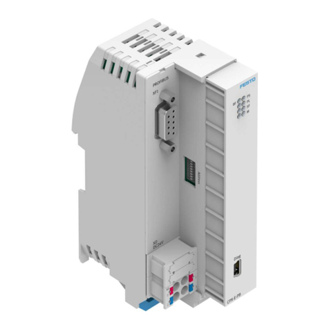
Bus module
CPX-E-PB
Festo AG & Co. KG
Ruiter Straße 82
73734 Esslingen
Germany
+49 711 347-0
www.festo.com
Instructions for use
Original instructions
8071115
2017-07
[8071117]
Bus module CPX-E-PB (PROFIBUS DP) English.............................
1 About this document
This document describes the use of the above-mentioned product. Certain aspects
of use are described in other documents and must be observed
è1.1 Further applicable documents.
PI PROFIBUS PROFINET®is a registered trademark of its respective trademark
holder in certain countries.
1.1 Further applicable documents
Document Content
Description of system CPX-E (CPX-E-SYS) Detailed description of the system CPX-E
Instructions for use of system CPX-E
(CPX-E-SYS)
Instructions and important notes on mounting,
electrical installation and maintenance tasks
for a system CPX-E
Description of bus module CPX-E-PB (CPX-E-PB) Detailed description of product function and
parameterisation options
Device description file (GSD) Definition of the modules of a system CPX-E for
integration into the higher-order controller
Documentation for the components in a system
CPX-E and the connected peripherals
Information on use of the components
Documentation for the higher-order controller
and the additional participants in the network
Information on commissioning and
parameterisation of the components
Fig. 1
All available documents for the product èwww.festo.com/pk.
1.2 Product version
This document refers to the following product versions:
Product Version number
CPX-E-PB Bus module CPX-E-PB, revision 3 onward
Fig. 2
The product version can be identified from the product label or with the help of
appropriate software from Festo.
Appropriate software for identifying the product version can be found in
the Festo Support Portal èwww.festo.com/sp. Information on using the
software can be found in the integrated Help function.
There may be an updated version of this document for these or later
product versions.
 Check whether a corresponding version of this document is available
inthe Festo Support Portal èwww.festo.com/sp.
1.3 Product labelling
The product label is located on the left-hand side of the module. Scanning the
printed Data Matrix Code with an appropriate device opens the Festo Support
Portal with the relevant documents for the product. Alternatively, the Product Key
(11-character alphanumeric code on the product label) can be entered in the
Support Portal search box.
Detailed information about product labelling can be found in the module
description è1.1 Further applicable documents.
1.4 Specified standards
Version status
EN 60529:2013-10 IEC 60204-1:2014-10
EN 61000-6-2:2009-04 IEC 61158:2014-07
EN 61000-6-4:2011-09 NE 21:2012-05
Fig. 3
2 Safety
2.1 General safety information
 Take into consideration the legal regulations for the respective location.
 Use the product only within the defined values è13 Technical data.
 Observe product labelling.
 Observe further applicable documents è1.1 Further applicable documents.
 Store the product in a cool, dry, UV-protected and corrosion-protected
environment. Ensure storage times are short.
 Before working on the product: Switch off the power supply and secure it
against being switched on again.
 Observe the handling specifications for electrostatically sensitive devices.
2.2 Use for intended purpose
The product described in this document is intended solely for use as an interface
between a system CPX-E and a higher-order controller through participation in
aPROFIBUS DP network.
The products must be used only as follows:
– Use only in an industrial environment: Outside of industrial environments, e.g. in
commercial and mixed-residential areas, actions to suppress interference may
have to be taken.
– Use only in combination with modules and components that are permissible for
the respective product variant èwww.festo.com/catalogue.
– Only use the product if it is in perfect technical condition.
– Only use the product in its original condition without unauthorised
modifications. Only the conversions or modifications described in this and the
further applicable documents are permitted.
2.3 Training of specialised personnel
Installation, commissioning, maintenance and disassembly should only be
conducted by qualified personnel.
The qualified personnel must be familiar with installation of electrical control
systems.
3 Further information
– Accessories èwww.festo.com/catalogue
– Spare parts èwww.festo.com/spareparts
4 Service
 Contact your regional Festo contact if you have technical questions
èwww.festo.com.
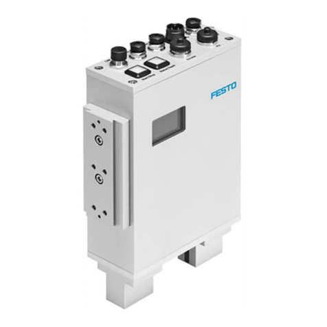
5 Product overview
5.1 Function
The product establishes, as a participant in a PROFIBUS DP network, the
connection between a higher-order controller and the modules of a system CPX-E.
5.2 Product design
1LED indicators
2DIL switch
3Diagnostic interface [DIAG]
(mini-USB)
4Operating voltage supply terminal
block UEL/SEN [XD]
5Terminal block lock
6Linking
7Network connection [XF1]
2
3
45
1
6
7
Fig. 4
5.3 Display components
1Network-specific LED indicator:
– Bus error [BF] (red)
2System-specific LED indicators:
– Operating voltage supply
UEL/SEN [PS] (green)
– Load voltage supply UOUT [PL]
(green)
– System fault [SF] (red)
– Force mode [M] (yellow)
2
1
Fig. 5
The network-specific LED indicators are described later in the document
è10 Diagnostics and fault clearance.
The system-specific LED indicators are described in “Instructions for use
ofsystem CPX-E” below è1.1 Further applicable documents.
5.4 Control components
DIL switches Function
1The station number of the bus module is set binary coded using
DIL switches 1 ... 7 (permissible station numbers 1 ... 125).
Factory setting: 3
Example: èFig. 7
2
3
4
5
6
7
8Device-specific diagnostics
ON = Active (factory setting)
OFF = Inactive
Fig. 6
Example of setting the station number
DIL 1: OFF 20= 1 Example:
DIL 2: ON 21=2 2
1+ 22+ 24= 2 + 4 + 16 = 22
DIL 3: ON 22=4
DIL 4: OFF 23=8 èStation number set = 22
DIL 5: ON 24=16
DIL 6: OFF 25=32
DIL 7: OFF 26=64
Fig. 7
5.5 Connecting components
Connection [XF1] Signal Designation
1 Shield Functional earth
2 n.c. –
3 RxD/TxD-P Received/transmitted data P
4 CNTR-P Repeater control signal1)
5 DGND Data reference potential (M5V)
6 VP Supply voltage positive (P5V)
7 n.c. –
8 RxD/TxD-N Received/transmitted data N
9 n.c. –
2) Shield Functional earth
1) The repeater control signal CNTR-P is executed as a TTL signal.
2) Housing
Fig. 8
Connection [XD]1) Signal
0+24 V DC operating voltage supply UEL/SEN
1
20 V DC operating voltage supply UEL/SEN
3
1) Ports XD.0 and XD.1 and ports XD.2 and XD.3, respectively, are connected to each other in the
terminalblock.
Fig. 9
Diagnostic interface [DIAG]
Via the diagnostic interface [DIAG] (mini-USB), the bus module can be connected
to a PC on which parameterisation and diagnostics software is installed.
6 Transport and storage
 Observe specifications for the environmental and storage conditions
è13 Technical data.
7 Mounting
 The module is to be mounted in accordance with the “Instructions for use of
system CPX-E” è1.1 Further applicable documents.
8 Installation
8.1 Network
 Use cables that meet the cable specification èFig. 15.
You can find the corresponding connector plugs in the Festo catalogue
èwww.festo.com/catalogue.
Bus terminal with terminating resistors
If the bus module is at the start or end of a field bus segment, a bus terminal is
required.
 Make sure that the bus terminal contains a resistor network having the following
configuration:
390 W390 W220 W
Pin 6 Pin 5
Pin 3 Pin 8
120 nH120 nH
Fig. 10
Connection with fibre-optic cables (FOC)
The PROFIBUS-DP interface of the module corresponds to the
specification IEC 61158 and supports the control of network components
for fibre-optic cables.
8.2 Operating voltage supply UEL/SEN
1. Make sure that the power supply is switched off.
2. Connect cables to the terminal block in accordance with the “Instructions for
use of system CPX-E” è1.1 Further applicable documents.
9 Commissioning
Note
Malfunction due to the higher-order controller and system CPX-E being switched
on in the incorrect order.
 Switch on the higher-order controller and system CPX-E according to the
preset order of the network used.
1. Set up automation project for the higher-order controller with the help of the
corresponding software.
2. Load the device description file into the software èwww.festo.com/sp.
3. Configure the system CPX-E in the software:
– System structure
– Network addressing
– I/O addressing
4. Transfer automation project to the higher-order controller.
Further information about commissioning the system CPX-E can be found
in the “Instructions for use of system CPX-E”. Information about the
parameters can be found in the “Description of system CPX-E” and in the
descriptions of the modules used è1.1 Further applicable documents.
Behaviour of display components following correct commissioning
[BF] (red) [PS] (green) [PL] (green) [SF] (red) [M] (yellow)
off lights up lights up off off
Fig. 11
Information about error elimination in the case of non-conforming
behaviour can be found in the “Description of system CPX-E” and in the
descriptions of the modules used è1.1 Further applicable documents.
10 Diagnostics and fault clearance
10.1 Diagnostics options
For the diagnostics of errors, various possibilities are available:
– Internal system diagnostics
– LED indicators on the product
10.2 Internal system diagnostics
 Activate internal system diagnostics via the corresponding catalogue input.
– Status bits: CPX-E-PB DP slave [status]
– I/O diagnostic interface: CPX-E-PB DP slave [DP-V1]
The internal system diagnostics is described in the “Description of
systemCPX-E” è1.1 Further applicable documents.
10.3 LED indicators
This document describes the network-specific LED indicators. The system-
specific LED indicators are described in the documentation for the system
CPX-E è1.1 Further applicable documents.
Bus error [BF]1)
LED (red) Meaning Remedy
flashes
Station number not correct
(e.g.address assigned twice)
 Check address setting of the
DILswitches in the bus module.
Bus interface faulty  Check bus interface of the master.
Bus connection interrupted or
short-circuited
 Check bus connection.
Faulty configuration  Check configuration of the master.
Bus connection poor or transmission
rate not detected
 Reduce transmission rate.
off
No error –
1) The behaviour of the LED indicator is dependent on parameterisation.
Fig. 12
11 Maintenance
Note
Accumulation of heat due to reduced air supply to electronics.
 Keep the ventilation slots clear and remove contamination regularly.
12 Disposal
 Dispose of the packaging, and of the product at the end of its useful life,
through environmentally friendly recycling in accordance with applicable
specifications.
13 Technical data
General
Feature Specification/value
General technical data, system CPX-E Description of system CPX-E
è1.1 Further applicable documents
Dimensions (length x width x height) [mm] 125.8 x 37.8 x 76.5
Product weight1) [g] 145
Mounting position Vertical/horizontal
Ambient temperature [°C] –5 … +60 (–5 … +50)2)
Storage temperature [°C] –20 … +70
Air humidity (non-condensing) [%] 0 … 95
Assigned address space (inputs/outputs)
Without diagnostics [bit] –/–
With status bits [bit] 8/–
With I/O diagnostic interface [bit] 16/16
Module code/submodule code (CPX-E-specific) 222/13
Module identification E-PB
DP identifier/IEC 61158
Without diagnostics 0/00h
With status bits 64/40h, 00h
With I/O diagnostic interface 192/C0h, 81h, 81h
Degree of protection in accordance with
EN60529
IP20
Protection against electric shock (protectionagainst
direct and indirect contact to IEC 60204-1)
Through the use of PELV circuits
(Protected extra-low voltage)
Electromagnetic compatibility To EN 61000-6-2/-4 and NE 21
1) Including linking
2) With horizontal mounting position
Fig. 13
Power supply
Feature Specification/value
Operating voltage supply UEL/SEN [V DC] 24 ± 25 %
Intrinsic current consumption at nominal
operating voltage 24 V from UEL/SEN
[mA] 50
Reverse polarity protection 24 V UEL/SEN against
0 V UEL/SEN
Yes
Mains buffering time [ms] 20
Fig. 14
Network-specific
Feature Specification/value
Connection technology Socket, Sub-D, 9-pin
Protocol PROFIBUS DP
Specification IEC 61158
PROFIBUS chip VPC3 with DVP1
Feature RS485
Type of transmission Serial asynchronous, half-duplex
Transmission rate [kbps] 9.6 … 12000
(automatic detection)
Maximum cable length per segment1) [m] 100 (at 3000 … 12000 kbps)
200 (at 1500 kbps)
400 (at 500 kbps)
1000 (at 187.5 kbps)
1200 (at 9.6 … 93.75 kbps)
Branch line length1)
1500 kbps [m] .6.6
,1500 kbps [m] No branch line allowed
Cable specification2)
Cable type Twisted-pair cable, screened
Surge impedance [Ω] 135 … 165 (3 … 20 MHz)
Capacitance per unit length: [pF/m] .30
Loop resistance [Ω/km] 110
Wire diameter [mm] ,0.64
Wire cross section [mm²] ,0.34
1) Dependent on transmission rate
2) To IEC 61158 (type A)
Fig. 15

Other Festo Control Unit manuals

Festo MX-2-1/4 User manual

Festo

Festo MX-2-1/4 User manual

Festo MS6N-SV-***-E-ASIS Series User manual

Festo

Festo MS6N-SV-***-E-ASIS Series User manual

Festo CPX Series Parts list manual

Festo

Festo CPX Series Parts list manual

Festo CP-FB13-E Parts list manual

Festo

Festo CP-FB13-E Parts list manual

Festo SPC200-COM-PDP User manual

Festo

Festo SPC200-COM-PDP User manual

Festo CPX Series User manual

Festo

Festo CPX Series User manual

Festo CPX-FB14 Parts list manual

Festo

Festo CPX-FB14 Parts list manual

Festo MS6-SV-...-E-10V24 Series User manual

Festo

Festo MS6-SV-...-E-10V24 Series User manual

Festo MSE6-C2M Parts list manual

Festo

Festo MSE6-C2M Parts list manual

Festo CPX-E-EP User manual

Festo

Festo CPX-E-EP User manual

Festo ZSB-1/8-B User manual

Festo

Festo ZSB-1/8-B User manual

Festo MS4/6-E-IPM-40-80 User manual

Festo

Festo MS4/6-E-IPM-40-80 User manual

Festo HSP AE Series User manual

Festo

Festo HSP AE Series User manual

Festo VOFC-LT-M32C Series User manual

Festo

Festo VOFC-LT-M32C Series User manual

Festo CPX-E-1CI User manual

Festo

Festo CPX-E-1CI User manual

Festo CPV..-DI01 series User manual

Festo

Festo CPV..-DI01 series User manual

Festo VIFB-21 Series User manual

Festo

Festo VIFB-21 Series User manual

Festo HSP-AE-IO Series Reference guide

Festo

Festo HSP-AE-IO Series Reference guide

Festo CP-FB11-E Parts list manual

Festo

Festo CP-FB11-E Parts list manual

Festo VZQA-C-M22U series User manual

Festo

Festo VZQA-C-M22U series User manual

Festo CHB-C-N User manual

Festo

Festo CHB-C-N User manual

Festo VZQA-C-M22C Series User manual

Festo

Festo VZQA-C-M22C Series User manual

Festo CAPC-F1-E-M12 User manual

Festo

Festo CAPC-F1-E-M12 User manual

Festo VAEM-V-S8EPRS2 User manual

Festo

Festo VAEM-V-S8EPRS2 User manual

Popular Control Unit manuals by other brands

Sony Ericsson GM47 Technical description

Sony Ericsson

Sony Ericsson GM47 Technical description

Dewetron DAQP-CFB2 Technical reference manual

Dewetron

Dewetron DAQP-CFB2 Technical reference manual

OMS P Valve instruction manual

OMS

OMS P Valve instruction manual

sparkfun ESP32 HOOK-UP GUIDE

sparkfun

sparkfun ESP32 HOOK-UP GUIDE

PIKO 36233 manual

PIKO

PIKO 36233 manual

VAT 62714-XE64-3 Series operating manual

VAT

VAT 62714-XE64-3 Series operating manual

Axel Larsson AL 25-90D Installation & maintenance

Axel Larsson

Axel Larsson AL 25-90D Installation & maintenance

Meinberg IMS-MRI Setup guide

Meinberg

Meinberg IMS-MRI Setup guide

Datakom DKG-519 user manual

Datakom

Datakom DKG-519 user manual

Leonard 170-LF INSTALLATION ADJUSTMENT SERVICE

Leonard

Leonard 170-LF INSTALLATION ADJUSTMENT SERVICE

entegris CR8 Manual Repair instructions

entegris

entegris CR8 Manual Repair instructions

ICP DAS USA tSH-700 Series quick start

ICP DAS USA

ICP DAS USA tSH-700 Series quick start

Belimo UGVL Series QUICK MOUNT VISUAL INSTRUCTION MANUAL

Belimo

Belimo UGVL Series QUICK MOUNT VISUAL INSTRUCTION MANUAL

YASKAWA VIPA IM 053IP manual

YASKAWA

YASKAWA VIPA IM 053IP manual

Kikusui PLZ150U Operation manuals

Kikusui

Kikusui PLZ150U Operation manuals

VIGOUR individual Assembly instructions and operation manual

VIGOUR

VIGOUR individual Assembly instructions and operation manual

Dinel PCU-100 Series user manual

Dinel

Dinel PCU-100 Series user manual

Vertiv eSure R48-1000e3 user manual

Vertiv

Vertiv eSure R48-1000e3 user manual

manuals.online logo
manuals.online logoBrands
  • About & Mission
  • Contact us
  • Privacy Policy
  • Terms and Conditions

Copyright 2025 Manuals.Online. All Rights Reserved.