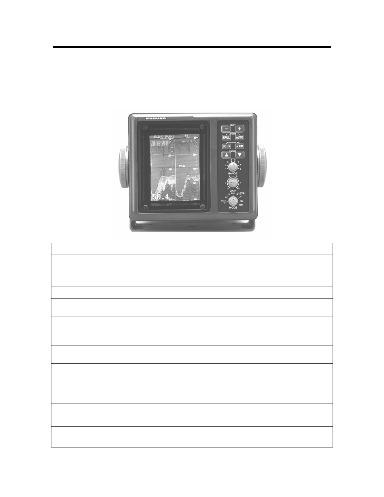
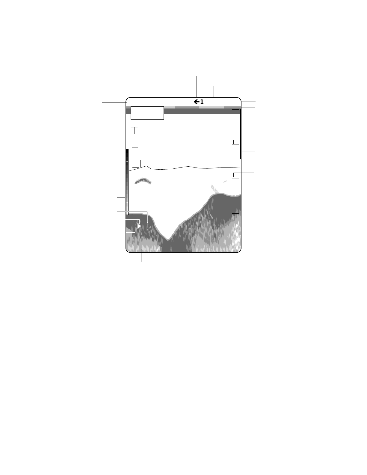
Furuno FCV-667 User manual


#
#
#
#
#
#
#
#
#
#
#
#
#
#
#
#
#
#
#
#
#
#
#
#
#
#
&#
<085/#$VKLKDUD0FKR/#
1LVKLQRPL\D/#-DSDQ#
7HOHSKRQH=# 3:<;09805444#
7HOHID[=# 3:<;09807533#
<RXU#/RFDO#$JHQW2'HDOHU#
$OO#ULJKWV#UHVHUYHG1#
38%1# 1R1# 20(056783#
)&9099:
#
+'$0,,#
),567#(',7,21#=#6(3# 4<<6#
#+#=#1291# 48/#4<<<#
3ULQWHG#LQ#-DSDQ#

i
SAFETY INSTRUCTIONS
WARNING
ELECTRICAL SHOCK HAZARD
Do not open the equipment.
Only qualified personnel
should work inside the
equipment.
Immediately turn off the power at the
switchboard if water leaks into the
equipment or something is dropped in
the equipment.
Continued use of the equipment can cause
fire or electrical shock. Contact a FURUNO
agent for service.
Do not disassemble or modify the
equipment.
Fire, electrical shock or serious injury can
result.
Do not place liquid-filled containers on
the top of the equipment.
Fire or electrical shock can result if a liquid
spills into the equipment.
Immediately turn off the power at the
switchboard if the equipment is emitting
smoke or fire.
Continued use of the equipment can cause
fire or electrical shock. Contact a FURUNO
agent for service.
Make sure no rain or water splash leaks
into the equipment.
Fire or electrical shock can result if water
leaks in the equipment.
CAUTION
A warning label is attached to the equip-
ment. Do not remove the label. If the
label is missing or illegible, contact
a FURUNO agent or dealer.
WARNING
To avoid electrical shock, do not
remove cover. No user-serviceable
parts inside.
Name: Warning Label (1)
Type: 86-003-1011-0
Code No.: 100-236-230
WARNING
Keep heater away from equipment.
A heater can melt the equipment's power
cord, which can cause fire or electrical
shock.
Use the proper fuse.
Fuse rating is shown on the equipment.
Use of a wrong fuse can result in damage
to the equipment.

ii
TABLE OF CONTENTS
INTRODUCTION ................................................ iii
PRINCIPLE OF OPERATION.............................. v
SYSTEM CONFIGURATION .............................. vi
1. CONTROLS, INDICATIONS........................ 1-1
1.1 Control Description ............................. 1-1
1.2 Indications .......................................... 1-2
2. BASIC OPERATION.................................... 2-1
2.1 Turning the Power On/Off ................... 2-1
2.2 Adjusting Brilliance.............................. 2-1
2.3 Display Mode Selection, Description ... 2-1
2.4 Adjusting Gain .................................... 2-6
2.5 Automatic Operation ........................... 2-6
2.6 Selecting Picture Advance Speed ....... 2-7
2.7 Display Range Selection ..................... 2-7
2.8 Erasing Weak Echoes......................... 2-8
2.9 Measuring Depth to a Fish School....... 2-9
2.10 A-scope Display .................................. 2-9
2.11 Menu Operation ................................ 2-10
2.12 Suppressing Interference .................. 2-13
2.13 Suppressing Low Level Noise ........... 2-13
2.14 Selecting Background
and Echo Colors ............................... 2-14
2.15 Alarms .............................................. 2-14
2.16 White Marker .................................... 2-16
2.17 Demonstration Picture....................... 2-16
2.18 Correcting Speed/Water Temperature
Readout ............................................ 2-17
3. INTERPRETING THE DISPLAY................... 3-1
3.1 Zero Line ............................................ 3-1
3.2 Fish School Echoes ............................ 3-1
3.3 Bottom Echo ....................................... 3-1
3.4 Surface Noise/Aeration ....................... 3-2
4. MAINTENANCE, TROUBLESHOOTING ..... 4-1
4.1 Maintenance ....................................... 4-1
4.2 Basic Troubleshooting ......................... 4-3
4.3 Diagnostics ......................................... 4-4
4.4 Transducer Check ............................... 4-5
4.5 Speed/Water Temperature
Sensor (option) Check.........................4-5
4.6 Restoring Default Settings................... 4-5
MENU TREE ................................................... A-1
SPECIFICATIONS ......................................... SP-1
INDEX

iii
INTRODUCTION
Congratulations on your choice of the FURUNO FCV-667 Color Video Sounder. We are
confident that you will enjoy many years of operation with this fine piece of equipment.
For over 50 years FURUNO Electric Company has enjoyed an enviable reputation for quality and
reliability throughout the world. This dedication to excellence is furthered by our extensive global
network of agents and dealers.
The FCV-667 is just one of the many FURUNO developments in the field of echo sounding. The
compact, lightweight but rugged unit is easy to install and operate and is suitable for both fresh
and saltwater applications.
This unit is designed and constructed to withstand the rigors of the marine environment.
However, to obtain optimum performance from this unit, you should carefully read and follow the
recommended procedures for operation and maintenance. No machine can perform to the
utmost of its ability unless it is installed, operated and maintained properly.
We would appreciate feedback from you, the end-user, about whether we are achieving our
purposes.
Thank you for considering and purchasing FURUNO equipment.
Features
The FCV-667 dual-frequency (50kHz and 200kHz) color video sounder has a large variety of
functions, all contained in a splash-proof rugged plastic case that is compact to fit small boats.
The principal features of the FCV-667 are
•User-friendly design for simplified operation.
•A wide variety of display modes: bottom-lock expansion, marker zoom and unique bottom
zoom displays.
•Potent 300 W transceiver.
•8-color presentation (including background) on a 6" diagonal CRT, providing vivid
presentation of underwater conditions.
•AUTO function permits unattended range and gain setting operations. The range scale and
gain change automatically so that the bottom is displayed in reddish brown or red on the
lower half of the screen.
•A-scope display gives excellent bottom fish discrimination, vital for bottom trawler and
lobster/crab potter.
•Digital and analog displays of navigational data.

iv
•Alarms: fish, bottom, water temperature (requires appropriate sensor).
•Six pulselengths for excellent performance on both shallow and deep ranges.
•Universal 12-24 VDC power supply drawing 30 W of power at maximum.
•Water temperature/speed sensor optionally available.

v
PRINCIPLE OF OPERATION
This Color Video Sounder determines the distance between its transducer and underwater
objects such as fish, lake bottom or seabed and displays the results on a 6-inch color screen.
It does this by utilizing the fact that an ultrasonic wave transmitted through water travels at a
nearly constant speed of 4800 feet (1500 meters) per second. When a sound wave strikes an
underwater object such as fish or sea bottom, part of the sound wave is reflected back toward
the source. Thus by calculating the time difference between the transmission of a sound wave
and the reception of the reflected sound wave, the depth to the object can be determined. In a
sense an echo sounder can be thought of as being an extremely sophisticated and quick timer,
since it is capable of resolving time differences shorter than one thousandth of a second.
The entire process begins in the display unit. Transmitter power is sent to the transducer as a
short pulse of electrical energy. The electrical signal produced by the transmitter is converted into
an ultrasonic signal by the transducer and transmitted into the water. Any reflected signals from
intervening objects (such as a fish school) are received by the transducer and converted back
into an electrical signal. It is then amplified in the amplifier section, and finally, displayed on the
screen.
The picture displayed by the color video sounder is made up of a series of vertical scan lines,
one for each transmission. Each line represents a "snapshot" of what has occurred beneath the
boat. The series of snapshots are accumulated side by side across the screen, and the resulting
contours of the bottom and fish between the bottom and surface are displayed. The amount of
history of objects that have passed beneath the boat over a series of transmission varies from
less than a minute to a few minutes, depending on how you adjust the unit.

vi
SYSTEM CONFIGURATION
Standard supply
520-5PSC-A
Optional supply
520-5PWC
520-5MSC-A
520ST-PWA
524ST-MSA
Ship's mains
12-24 VDC
External equipment
(GPS navigator, etc.)
TRANSDUCER
SPEED, TEMPERATURE SENSOR (option)
Speed/temperature sensor
ST-02MSB
ST-02PSB
ST-01PTB
Temperature sensor
T-02MTB
T-02MSB
T-03MSB
DISPLAY UNIT
CV-667

1-1
1. CONTROLS, INDICATIONS
1.1 Control Description
The equipment is so designed that even a first time user can quickly become acquainted with the
operating procedure. Operation of each control or key is acknowledged by an alphanumeric
message or symbol indication on the screen.
Control Function
SHIFT-, SHIFT+
(Appears in text as [-], [+].) •Change display start depth.
•Select options on menus.
BRILL Adjusts brilliance of display.
AUTO Turns the automatic sounder adjustment feature on/off.
ADVANCE (BRILL + AUTO) Pressing the BRILL and AUTO keys together selects display
advancement speed.
SIG LEV Eliminates low intensity echoes (up to light-blue echoes) in two
steps.
ALARM Opens/closes the alarm menu.
A-SCOPE (SIG LEV + ALARM) Pressing the SIG LEV and ALARM keys together displays the
A-scope display at the right 1/4 of the screen.
MARKER ▲, MARKER ▼
(Appears in text as [▲] or [▼].) •Shift the Variable Range Marker (VRM).
•Set alarm zone.
•Select menu items.
•Set white marker.
RANGE Sets the basic range of the display.
GAIN Adjusts receiver sensitivity.
MODE •Turns unit on/off.
•Selects display mode.

1-2
1.2 Indications
Water
temperature*
Speed*
Noise Limiter
Picture Advance Speed
Signal Level
Active alarm
Range scale
Variable range
marker (green)
w/depth readout
Depth
Color
bar
Water temperature
scale*
Minute marker
(yellow, blue,
30 sec. each)
Nav data*
Alarm zone
marker
35°15.000' N
135°07.500' W
AUTO-1
Alarm Icon
Auto Setting
Alarm Type
(F,B,TI,TB)
(DEMO)
Demonstration Mode
49.8˚F 12.5kt NL1
ç
1 SL1
0
20
40
60
80
49.6
39.8
Water temperature
marker* (Color
changes with
HUE setting.)
* Requires appropriate sensor.
All indications and
markers are displayed
in white unless
noted otherwise.
F
30
40
50
60
70

2-1
2. BASIC OPERATION
2.1 Turning the Power On/Off
Turn the [MODE] switch clockwise to turn the power on. The unit starts with the settings used
before it was turned off last time. Note that there is a few seconds delay prior to display of the
picture until the CRT warms up. To turn the power off, turn the switch fully counterclockwise.
2.2 Adjusting Brilliance
Use the [BRILL] key to adjust the brilliance. The selected brilliance level is shown on the display
as below. There are six levels of brilliance including off. Keep the brilliance moderate to extend
the life of the CRT.
BRILL: 0
2.3 Display Mode Selection, Description
2.3.1 Display mode selection
Seven display modes are available and you may select one of them with the [MODE] switch.
MODE switch description
MODE Switch
Position Function
HF Provides the high frequency (200 kHz) normal picture on the full screen.
LF Displays the low frequency (50 kHz) normal picture on the full screen.
DUAL Displays the normal display for high frequency (200 kHz) on right half and that for
the low frequency (50 kHz) on the left half.
HF ZOOM Shows the normal display of the high frequency (200 kHz) on right half and its
zoom display on the left half.
LF ZOOM Provides the normal display of the low frequency (50 kHz) on right half and its
zoom display on the left half.
NAV Shows navigation data in analog or digital form (depending on menu setting) on
the full screen.
MENU Displays the main and system menus.

2-2
2.3.2 Display mode description
HF, LF (high frequency, low frequency) mode
The sounder uses ultrasonic pulses to detect bottom conditions. The lower the frequency of the
pulse the wider the detection area. Therefore, the 50 kHz frequency is useful for general
detection and judging bottom conditions, while the 200 kHz frequency is useful for detailed
observation of fish schools.
49.6
0.0
Fish
school
Bottom
0
20
40
60
80
DUAL frequency mode
This mode provides the 50 kHz picture on the left-half of the screen and the 200 kHz on the right
half, and is useful for detecting fish schools which have different reflection characteristics with
frequency. For example, a school of tiny fish like minnow returns stronger echoes on a high
frequency compared to a low frequency.
60
49.6
0.0
50 kHz 200 kHz
picture picture
0
20
40
80
0
20
40

2-3
ZOOM mode (high or low frequency)
Three types of zoom displays are available: bottom-lock expansion, bottom zoom and marker
zoom. The zoom mode to be used can be selected on the main menu with ZOOM MODE.
5
Fish
220.7
0
40
Bottom-
lock
display
Normal
display
Zoom marker (yellow)
Thissection
iszoomed
10
20
30
0
4
3
2
1
BOTTOM-LOCK
This display provides a compressed normal picture on the
top 2/3 of the screen and a 5 or 10 meter (10 or 20 feet)
wide layer in contact with the bottom is expanded onto the
bottom 1/3 of the screen. This mode is useful for bottom
discrimination. Note that the seabed should be steadily
and distinctly plotted in red or reddish-brown. Adjust the
gain if necessary.
Note 1: The bottom-lock range can be selected on the
system menu [3].
Note 2: The zoom marker can be turned on/off on the
system menu [1].
0
10
20
30
40
15
20
25
36.4
Normal
display
Zoom
marker
(yellow)
Bottom
Bottom-zoom display
BOTTOMZOOM
This mode expands bottom and bottom fish echoes two to
five times to vertical size of the screen, and it is useful for
determining bottom hardness. A bottom displayed with a
short echo tail usually means it is a soft, sandy bottom. A
long echo tail means a hard bottom.
The zone automatically moves so that the bottom echoes
locate on the lower half of the screen.
Note 1: The amount of expansion can be selected on the
system menu [3].
Note 2: The zoom marker can be turned on/off on the
system menu [1].
14.7
0
10
20
30
40
15
20
25
28.2
Zoomedfish
school
Normal
display
Variable range
marker (green)
This section
is zoomed
Zoom marker
(yellow)
Marker-zoom
display
Fish
school
MARKER ZOOM
This mode expands selected area of the normal picture to
full vertical size of the screen on the left-half window. You
may specify the portion to expand with the VRM (Variable
Range Marker), which you can shift with [▲] or [▼]. The
area between the VRM and the zoom range marker is
expanded. The length of the segment is equal to one
division of the depth scale.

2-4
NAV mode
This mode shows navigation data digitally or graphically. The nav display to use can be selected
on the system menu [1] with NAV.
0
20
40
60
80
50
0
40
30
20
10
TRIP NM
123.0
SPEED
10.6 KT
DEPTH
151ft
( : 19 25)
TEMP
84.7˚F
WPT: FOX1 35˚23.19'N
122˚46.90'E
CSE: 120˚
BRG: 135˚
RNG
100.5NM
1 0.5 00.5 1
XTE
0.5 S
NM
Trip Distance*
Speedometer* Speed*
Depth Alarm Range
Water Temperature*
Ship's Position*
Bearing to Waypoint
relative to ship's course*
Cross-Track Error*
(Shows amount and direction
to steer to return to course.
The example shows you should
steer 0.5 nm starboard to return to course.)
Waypoint*
Bearing
to Waypoint*
Course*
* Requires appropriate sensor.
0
20
40
60
80
35
°
23. 19'N
122
°
46. 90'E
151ft
84.7 ˚F
10.6kt
Depth
Water Temperature*
Speed*
Position*
* Requires appropriate sensor.

2-5
Enlarging a nav data indication
You can enlarge and display one of the data indications as follows.
1. Press [▲] or [▼] to select the indication which you want to enlarge. For example, select the
depth indication.
2. Press the [+] key to enlarge the data.
0
20
40
60
80
151
ft
3. To return to the full data display, press the [-] key.

2-6
2.4 Adjusting Gain
The [GAIN] control adjusts the sensitivity of the receiver. Adjust it so that a slight amount of noise
remains on the screen. Generally, use a higher gain setting for greater depths and a lower
setting for shallower waters.
Note: The [GAIN] control is inoperative when the automatic mode is active.
Gain too high Gain proper Gain too low
2.5 Automatic Operation
Automatic operation is useful when you are preoccupied with other tasks and do not have time to
adjust the display.
2.5.1 How it works
The automatic function automatically selects the proper gain and range scale according to depth.
It works as follows:
•The range changes automatically to locate the bottom on the lower half of the screen. It
jumps to one step shallower range when bottom echoes reach a halfway point of the full scale
from top and to one step deeper range when they come to the lower edge of the scale.
•The gain is automatically adjusted to display the bottom echo in reddish-brown (default color
arrangement).
•Clutter level (on the main menu), which suppresses low level noise, is automatically adjusted.
2.5.2 Enabling automatic operation
Two types of automatic modes are available: AUTO 1, for fishing, and AUTO 2, for cruising.
Since cruising uses a higher clutter rejection setting than fishing, it is not recommended for
detection of fish because weak fish echoes may be deleted by clutter rejection. Note that the
[SHIFT] keys ([+], [-]), [RANGE] switch and [GAIN] control are inoperative in the auto mode.
Press the [AUTO] key. Each press of the key turns the auto function on or off in the sequence
shown below.
AUTO-1 ON
(FISH MODE)
AUTO-2 ON
(CRUISE MODE) AUTO OFF

2-7
2.6 Selecting Picture Advance Speed
The picture advance speed determines how quickly the vertical scan lines run across the screen.
When selecting a picture advance speed, keep in mind that a fast advance speed will expand the
size of the fish school horizontally on the screen and a slow advance speed will contract it.
1. Press the [BRILL] and [AUTO] keys together. The display should look something like the one
below. The fraction shown on the display denotes number of scan lines produced per
transmission. For example, 1/8 means one scan line is produced every eight transmissions.
"0" freezes the display and it is convenient for observing an echo.
ADVANCE: 1
(1/8)
2. Continue pressing the [BRILL] and [AUTO] keys together to select desired speed.
2.7 Display Range Selection
The basic range and range shifting functions used together give you the means to select the
depth you can see on the screen. The basic range can be thought of as providing a "window" into
the water column and range shifting as moving the "window" to the desired depth.
Display
Shift
2.7.1 Basic range selection
The basic range may be selected with the [RANGE] switch from the eight ranges shown in the
table below.
Table 1-1 Basic ranges (default settings)
RangeNo.12345678
Meters 5 10 20 40 80 150 200 300
Feet 15 30 60 120 200 400 600 1000
Fathoms 3 5 10 20 40 80 100 150
Passi/Braza (P/B) 3 5 10 30 50 100 150 200

2-8
Operate the [RANGE] switch and the display shown below appears. Adjust the [RANGE] control
again to select a basic range.
RANGE: 30 ft
Note: The [RANGE] switch is inoperative when the auto function is active.
2.7.2 Range shifting
The basic range may be shifted up or down with the [SHIFT] keys ([+], [-]). Press a [SHIFT] key
and the display shown below appears. Press a [SHIFT] key again to select the amount of shift.
SHIFT: 0 ft
Note 1: The maximum shift range is 1000 feet (300 m). However, actual range will depend on
underwater conditions. In the worst case echoes will not appear.
Note 2:Basic ranges can be changed on the system menu [3].
Note 3: The unit of depth may be selected on the system menu [1].
Note 4: The range cannot be shifted when the auto function is active.
2.8 Erasing Weak Echoes
Dirty water or reflections from plankton may be painted on the display in green or light-blue.
These weak echoes may be erased as follows:
1. Press the [SIG LEV] key. The following display appears.
SIGLVL: 1
2. Press the [SIG LEV] key again to select signal level (echo color) to erase. Every pressing
deletes the weakest color echoes on the screen, up to the light-blue echoes. You may
identify the deleted colors on the color bar; deleted colors disappear from the color bar. The
selected level is shown as SL1, SL2 or SL3 at the top of the screen. Signal level "0" disables
this function.

2-9
2.9 Measuring Depth to a Fish School
The VRM (Variable Range Marker) functions to measure the depth to fish schools or other echo.
1. Press [▲] or [▼] to place the VRM on an echo.
2. Read the VRM range just above the VRM.
0
20
40
60
80
49.6
39.8
VRM (green)
2.10 A-scope Display
This display shows echoes at each transmission with amplitudes and tone proportional to their
intensities, on the right 1/4 of the screen. It is useful for estimating the kind of fish school and
bottom composition. To turn the A-scope display on or off press the [SIG LEV] and [ALARM]
keys together.
32.3
10
20
30
40
A-scope
display
Normal
display
0.0
0

2-10
2.11 Menu Operation
The menu, consisting of the main menu and three system menus, contains less often used
functions which do not require frequent adjustment.
2.11.1 Menu selection
1. Set the [MODE] switch in the MENU position.
M/Z B/L B/Z
0 (-20 - +20)
OFF 1 2 3
NOISE LIMITER
HUE SELECTION
1 (1 - 7)
0 (-20 - +20)
GAIN ADJUST 200KHZ
GAIN ADJUST 50KHZ
CLUTTER LEVEL
0 * (0 - 3)
ZOOM MODE (B.LOCK)
/:TO SELECT ITEM, 1/2
-/+ : TO SET CONDITION.
* A shown when
auto mode is
active.
2. To go to page 2 of the main menu, select ZOOM MODE (B. LOCK) with [▼] and then press
[▼] again.
VRM WHT
MARKER (VRM)
GO TO SYSTEM MENU
NO YES
/:TO SELECT ITEM, 2/2
-/+ : TO SET CONDITION.
3. To go to the system menu, press [▼] to select GO TO SYSTEM MENU and [+] to select YES.
You can switch among system menus by selecting MENU and using [+] or [-].
Table of contents
Other Furuno Marine Equipment manuals

Furuno
Furuno MF/HF DSC/Watch Receiver DSC-60 User manual

Furuno
Furuno TZTL15F Manual

Furuno
Furuno 520 User manual

Furuno
Furuno FCV-1500 User manual

Furuno
Furuno FCV-1150 User manual

Furuno
Furuno FCV-30 User manual

Furuno
Furuno FCV-291 User manual

Furuno
Furuno LS-6100 User manual

Furuno
Furuno FE-700 Quick start guide

Furuno
Furuno FCV-1150 User manual

Furuno
Furuno FMD3100 User manual

Furuno
Furuno VR-7000 User manual

Furuno
Furuno FE-700 User manual

Furuno
Furuno 3D Sonar Visualizer F3D-S User manual

Furuno
Furuno IF-7000 User manual

Furuno
Furuno DSC-6 User manual

Furuno
Furuno 1824C-BB User manual

Furuno
Furuno FEA-2807 User manual

Furuno
Furuno Navtex NX-700-B User manual

Furuno
Furuno MFDBB User manual