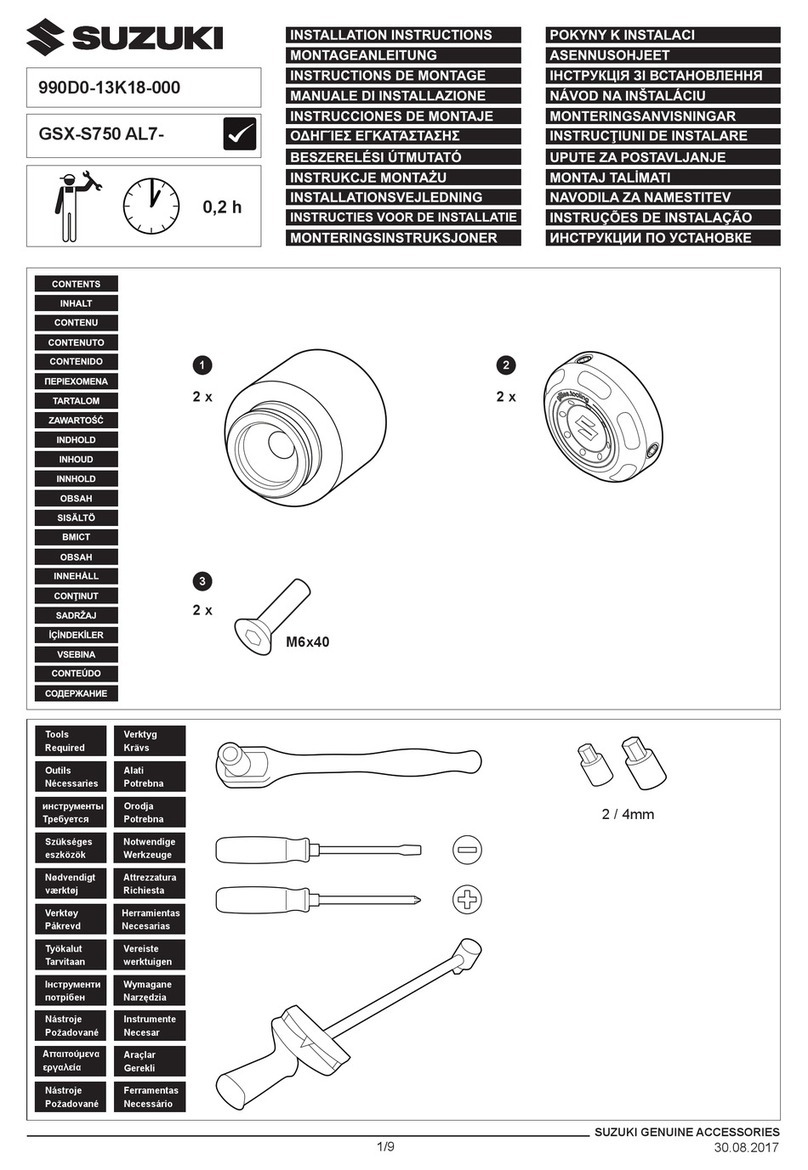
Gazzini 10020889 Guide

1
de| Original
Montageanleitung
en| Instructions
installation
fr| Instructions
de montage
it
| Istruzioni
di montaggio

2
INHALTSVERZEICHNIS
1 | Lieferumfang 3
2 | Allgemeines 4
2.1 | Anleitung lesen
und aufbewahren 4
2.2 | Zeichenerklärung 4
3 | Sicherheit 4
3.1 | Bestimmungsgemäßer
Gebrauch 4-5
3.2 | Sicherheitshinweise 5-6
4 | Montage 6
4.1 | Gesetzliche Vorgaben
zur Montage von Blinkern 6-7
4.2 | Vorbereitung 7
4.3 | Anbau 7-8
5 | Lagerung 8
6 | Reinigung und Pflege 8
7 | Gewährleistung 8-9
8 | Entsorgung 9
9 | Kontakt 9
de |ORIGINALE MONTAGEANLEITUNG

3
BLINKERHALTE-SET
(Best.Nr. 10020889)
1 | LIEFERUMFANG
1|
2|
4|
6|
5|
7|
2x Blinkerhalter (Teil A)
2x Blinkerhalter (Teil B)
2x Zylinderschraube mit Innensechskant DIN 912 M4 x 12 A2
2x Distanzklebestreifen 0,5 mm
2x Distanzklebestreifen 1,0 mm
2x Distanzklebestreifen 1,5 mm
2x Distanzklebestreifen 2,0 mm
4x Japanstecker
4x Hülle für Japanstecker
1
2
3
4
5
6
7
8
9
3|
8|
9|

4
2 | ALLGEMEINES
2.1 |Anleitung lesen und aufbewahren
Diese Montageanleitung bezieht sich ausschließlich auf das
genannte gazzini Blinkerhalte-Set. Sie enthält wichtige Hinweise
zu Anbau, Sicherheit und Gewährleistung. Lesen Sie die
Anleitung, insbesondere die Sicherheitshinweise, sorgfältig
durch, bevor Sie das gazzini Blinkerhalte-Set montieren.
Die Nichtbeachtung kann zu Schäden am Fahrzeug führen.
Bewahren Sie die Anleitung für die weitere Nutzung auf. Wenn
Sie die gazzini Blinkerhalter an Dritte weitergeben, geben Sie
unbedingt diese Anleitung mit.
Die Montageanleitung basiert auf den in der Europäischen
Union gültigen Normen und Regeln. Beachten Sie im Ausland
auch landesspezifische Richtlinien und Gesetze.
2.2 |Zeichenerklärung
Die folgenden Symbole und Signalwörter werden in dieser
Anleitung verwendet.
3 | SICHERHEIT
3.1 |Bestimmungsgemäßer Gebrauch
Die vorliegenden gazzini Blinkerhalter können zur Montage von
Blinkern am Standrohr des Motorrads verwendet werden. Sie
WARNUNG!
Dieses Signalsymbol/-wort
bezeichnet eine Gefährdung
mit einem mittleren Risikograd,
die, wenn sie nicht vermieden
wird, den Tod oder eine schwere
Verletzung zur Folge haben kann.
VORSICHT!
Dieses Signalsymbol/-wort
bezeichnet eine Gefährdung mit
einem niedrigen Risikograd, die,
wenn sie nicht vermieden wird,
eine geringfügige oder mäßige
Verletzung zur Folge haben kann.
HINWEIS!
Dieses Signalwort warnt vor
möglichen Sachschäden.

5
passen an Standrohre mit 38, 39, 40 oder 41 mm Durchmesser
und sind für Blinker mit einem M8x1.25 Gewinde geeignet.
3.2 |Sicherheitshinweise
WARNUNG!
Gefahren für Kinder und Personen mit
verringerten physischen, sensorischen oder
mentalen Fähigkeiten (beispielsweise teilweise
Behinderte, ältere Personen mit Einschränkung
ihrer physischen und mentalen Fähigkeiten)
oder Mangel an Erfahrung und Wissen
(beispielsweise ältere Kinder).
Zum Lieferumfang gehören verschluckbare
Kleinteile sowie Verpackungsmaterial. Halten
Sie diese Teile von Kindern fern, da beim
Verschlucken Erstickungsgefahr besteht.
VORSICHT!
Verletzungsgefahr!
Vergewissern Sie sich vor jeder Fahrt, dass
die Blinkerhalter korrekt festgezogen sind.
Vergewissern Sie sich, dass die montierten
Blinker durch veränderte Abmessungen, durch
Zubehör oder durch Gepäck am Fahrzeug
unter keinen Umständen verdeckt werden
können.
HINWEIS!
Kurzschlussgefahr!
Vor den Arbeiten an der Fahrzeugelektrik
klemmen Sie unbedingt die Fahrzeugbatterie
ab - es besteht Kurzschlussgefahr!

6
Die Elektroinstallation sowie der mechanische
Anbau am Fahrzeug müssen fachgerecht
ausgeführt werden. Ein fehlerhafter Anbau kann
Kurzschlüsse verursachen oder zum Erlöschen
der Betriebserlaubnis führen.
HINWEIS!
Beschädigungsgefahr!
Achten Sie bei Montagearbeiten auf einen
sicheren Stand des Fahrzeugs und einen gut
beleuchteten Arbeitsplatz.
Auf die Elektrokabel des Blinkers dürfen
keinerlei Zugkräfte wirken, auch bei
Volleinschlag der Lenkung. Sie müssen
geschützt verlegt werden, sodass die Kabel
nicht aufscheuern können und sie dürfen nicht
abknicken.
4 | MONTAGE
4.1 |Gesetzliche Hinweise zur Montage von Blinkern:
Ist das Motorrad nach EG-Recht (fast alle Fahrzeuge ab
Erstzulassung ca. 1998) zugelassen worden, gelten die
folgenden Maße:
Abstand der vorderen Blinker zueinander mindestens 240 mm
(Innenkante Blinker-Glas zu Innenkante Blinker-Glas), Höhe
von der Fahrbahn 350 – 1200 mm.
Ist das Motorrad nach deutschem Recht (ältere Fahrzeuge vor
1998) zugelassen, bei der Montage bitte die folgenden Maße
gemäß StVZO einhalten:

7
Abstand der vorderen Blinker zueinander mindestens 340 mm
(Innenkante Blinker-Glas zu Innenkante Blinker-Glas), bei je
100 mm Abstand zum Scheinwerfer (Kante-Kante)
Mindesthöhe zur Straße/ zum Boden 350 mm (Unterkante)
4.2 |Vorbereitung
Bocken Sie das Fahrzeug sicher auf. Klemmen Sie die
Fahrzeugbatterie ab. Demontieren Sie die vorhandenen
vorderen Blinker, trennen Sie die Anschlusskabel.
4.3 |Anbau
Montieren Sie die neuen Blinker zunächst lose an den gazzini
Blinkerhaltern und führen Sie das Kabel sorgfältig durch den
Kabelkanal. Ermitteln Sie den Standrohrdurchmesser und kleben
Sie soweit notwendig den passenden Distanzklebestreifen innen
in die Halterhälften. Setzen Sie die Halterhälften übereinander
an das Standrohr und führen sie Sie zusammen. Achten Sie
darauf, dass das Kabel gut im Kabelkanal des Halters liegt und
nicht eingeklemmt wird, während Sie die Zylinderkopfschraube
mit Hilfe eines Innensechskantschlüssels (Größe 3 mm) in den
Halter eindrehen und diesen am Standrohr handfest anziehen.
min. 240 mm
0-75 mm
(Mindestmaß
je nach
Leuchtstärke)

8
Achten Sie auf gute Ausrichtung der Blinker parallel zur Straße
und im 90 Grad Winkel zur Fahrzeuglängsachse. Ziehen Sie
sodann die Kontermutter mit einem Maulschlüssel (12 mm)
mit Gefühl fest. Möchten Sie aus optischen Gründen auf die
Kontermutter verzichten, geben Sie etwas mittelfeste flüssige
Schraubensicherung auf das Gewinde, auch auf diese Weise
wird eine ausreichende Festigkeit erzielt. Sorgen Sie nun
für den Kabelanschluss der Blinker und überprüfen Sie ihre
einwandfreie Funktion. Beachten Sie diesbezüglich die dem
Blinker beigefügte Anleitung.
5 | LAGERUNG
Lagern Sie die nicht montierten Blinkerhalter in einem vor
Witterung und Feuchtigkeit geschützten, geschlossenen Raum.
Die Luftfeuchtigkeit von max. 80% sollte nicht überschritten
werden.
6 | REINIGUNG UND PFLEGE
Reinigen Sie die Blinkerhalter mit warmer, milde Seifenlauge
oder Motorradreiniger und einem weichen Tuch. Verwenden
Sie keinen scharfen Reiniger, der Aluminium angreifen könnte.
Verwenden Sie abschließend ein wachshaltiges Pflegemittel,
das die Oberfläche gegen Witterungseinflüsse schützt.
7 | GEWÄHRLEISTUNG
Für das vorliegende gazzini Blinkerhalte-Set gilt die gesetzliche
Gewährleistung von zwei Jahren. Der Gewährleistungszeitraum
beginnt ab dem Kaufdatum. Gebrauchsspuren,
Zweckentfremdung, nicht bestimmungsgemäßer Gebrauch
und Schäden, die aus einem Unfall, einer Manipulation oder
Blinker nicht im Lieferumfang

9
einem Reparaturversuch durch unautorisierte Kundendienste
oder Personen resultieren, sind von der Gewährleistung ausge-
schlossen.
8 | ENTSORGUNG
Verpackung entsorgen
Entsorgen Sie die Verpackung sortenrein. Geben
Sie Pappe und Karton zum Altpapier, Folie in die
Wertstoffsammlung.
Blinkerhalter entsorgen
(Anwendbar in der Europäischen Union und anderen
europäischen Staaten mit Systemen zur getrennten Sammlung
von Wertstoffen)
Entsorgen Sie die unbrauchbar gewordenen Blinkerhalter in
einer Wertstoffsammlung für Altmetall.
9 | KONTAKT
Bei Fragen zum Produkt und/oder dieser Anleitung kontaktieren
Sie vor dem ersten Gebrauch des Produktes unser Servicecenter
weiter. So gewährleisten wir gemeinsam, dass das Produkt
korrekt benutzt wird.
Hergestellt in Taiwan
Blinker nicht im Lieferumfang

10
CONTENTS
1 | Scope of delivery 11
2 | General information 12
2.1 | Reading and keeping
these instructions 12
2.2 | Explanation of symbols 12
3 | Safety 12
3.1 | Intended use 12
3.2 | Safety instructions 13-14
4 | Installation 14
4.1 | Legal requirements
for the installation
of turn signals 14-15
4.2 | Preparation 15
4.3 | Installation 15-16
5 | Storage 16
6 | Cleaning and Care 16
7 | Warranty 16
8 | Disposal 16
9 | Contact 17
en |TRANSLATION OF ORIGINAL INSTALLATION
INSTRUCTIONS

11
TURN SIGNAL MOUNT SET
(Order no. 10020889)
1 | SCOPE OF DELIVERY
1|
2|
4|
6|
5|
7|
2x turn signal bracket (Part A)
2x turn signal bracket (Part B)
2x cylinder-head screw with hex socket DIN 912 M4 x 12 A2
2x adhesive spacer strip 0.5 mm
2x adhesive spacer strip 1.0 mm
2x adhesive spacer strip 1.5 mm
2x adhesive spacer strip 2.0 mm
4x Japanese connectors
4x sleeves for Japanese connectors
1
2
3
4
5
6
7
8
9
3|
8|
9|

12
2 | GENERAL INFORMATION
2.1 |Reading and keeping the installation instructions
These instructions apply exclusively to the stated gazzini Turn
Signal Mount Set.
They contain important information on installation, safety and
the warranty. Read the instructions carefully, in particular the
safety instructions, before using the gazzini Turn Signal Mount
Set. Failure to follow the instructions may cause damage to the
vehicle. Keep these instructions for future reference. If you pass
on the gazzini Turn Signal Mounts to a third party, you must
hand over these instructions.
The installation instructions are based on the standards and
regulations valid in the European Union. If abroad, observe
country-specific guidelines and laws.
2.2 |Explanation of symbols
The following symbols and signal words are used in these
instructions.
3 | SAFETY
3.1 |Intended use
These gazzini Turn Signal Mounts can be used for installing turn
signals on your motorcycle forks. They fit on 38, 39, 40 and
41 mm diameter forks and are compatible with an M8 x 1.25
thread.
WARNING!
This signal word/symbol
indicates a hazard with a
medium risk level which, if not
avoided, may result in death or
serious injury.
CAUTION!
This signal word/symbol
indicates a hazard with a low risk
level which, if not avoided, may
result in minor or moderate injury.
NOTE!
This signal word warns of
possible material damage.

13
3.2 |Safety instructions
WARNING!
Danger for children and persons with reduced
physical, sensory or mental abilities (e.g.
partially disabled persons and elderly persons
with reduced physical and mental abilities) or
lack of experience and knowledge (e.g. older
children).
This product includes small parts and
packaging which could be swallowed. Keep
these parts out of the reach of children to avoid
the danger of swallowing and choking or
suffocation.
CAUTION!
Risk of injury!
Ensure that your turn signals are securely
mounted and working correctly before every
journey.
Once you have installed the turn signals, make
sure that they cannot under any circumstances
be obscured due to changes in dimensions, or
by accessories or luggage on the vehicle.
NOTE!
Danger of short-circuit!
Before carrying out any work on the vehicle
electrical system, be sure to disconnect the
vehicle battery, as there is a danger of short-
circuit!
It is important that both electrical and
mechanical installation is carried out correctly.

14
Incorrect installation can cause short-circuits or
invalidate the type approval.
NOTE!
Risk of damage!
When installing the product, ensure that your
motorcycle cannot topple over, and that your
workplace is well lit.
The electric cables of the turn signal must not
be subject to any strain, even when the steering
is at full lock. The cables must be routed in such
a way that they are protected against chafing
and kinking.
4 | INSTALLATION
4.1 |Legal requirements for the installation of turn signals
If your motorcycle was registered according to EC law (almost
all vehicles first registered in approx. 1998 or later), the
following measurements apply:
Distance of at least 240 mm between the front turn signals
(inside edge of one turn signal lens to the inside edge of the
other lens), height above the road surface 350 mm - 1200 mm.
If your motorcycle was registered according to German law
(older vehicles prior to 1998), please observe the following
measurements required by the German Road Traffic Licensing
Regulations (StVZO) when you install the turn signals.
min. 240 mm
0-75 mm
(Minimum
dimensions
depending on
luminous intensity)

15
Distance of at least 340 mm between the front turn signals
(inside edge of one turn signal lens to inside edge of the other
lens), and both 100 mm from the headlight (edge to edge)
Minimum height above the road/ground 350 mm (bottom
edge)
4.2 |Preparation
Place the motorcycle securely on the stand. Disconnect the
vehicle battery. Remove the existing front turn signals and
disconnect the connecting cables.
4.3 |Installation
Begin by attaching the new turn signals to the gazzini mounts
without tightening them up, and feed the cable carefully
through the cable duct. Measure the diameter of the fork and, if
necessary, attach the correct adhesive spacer strip to the inside
of the clamp halves. Position the clamp halves on the fork, one
each side, align them with each other, and snap together.
Make sure that the cable fits snugly in the cable duct of the
clamp and is not jammed against an edge while you insert and
tighten the screw into the fork clamp. Ensure that the turn signals
are well aligned parallel to the road and at a 90° angle to the
Turn signal not included!

16
motorcycle's longitudinal axis. Then carefully tighten the lock nut
using an open-end wrench (12 mm). If, for aesthetic reasons,
you prefer not to use the lock nut, apply some medium-strength
liquid threadlocker to the thread. This will also give sufficient
strength. Connect the cables of the new turn signals and check
that they function perfectly. For this, you should refer to the
instructions provided with the turn signals.
5 | STORAGE
Store the turn signal in a closed room that is protected against
moisture. Humidity should not exceed 80%.
6 | CLEANING AND CARE
Use warm soapy water or a motorcycle cleaner and a soft cloth
for cleaning the turn signal mounts. Do not use harsh cleaning
agents which could corrode the aluminium. Afterwards, use a
wax-based polish which will protect the surfaces against the
elements.
7 | WARRANTY
Your gazzini Turn Signal Mount Set is covered by the statutory
two-year warranty. The warranty period begins on the date
of purchase. The warranty does not cover normal wear and
tear, nor use for anything other than the intended purpose, or
damage caused by an accident, manipulation or any attempt to
carry out repairs by unauthorised persons or customer service
providers.
8 | DISPOSAL
Packaging disposal
Please dispose of the packaging properly. Dispose
of card and cardboard together with waste paper,
and dispose of plastic film with recyclables.
Disposal of turn signal mounts
(Applicable in the European Union and other countries of
Europe that have systems for separate collection of recyclables)
Turn signal mounts that are no longer serviceable should be
disposed of as recyclable scrap metal.

17
9 | CONTACT
If you have any questions about this product and/or these
instructions, before using the product for the first time, please
feel free to contact our Service Centre by e-mail at:
the best way to ensure that your product is used correctly.
Made in Taiwan

18
SOMMAIRE
1 | Équipement fourni 19
2 | Généralités 20
2.1| Lire et conserver les
présentes instructions
de montage 20
2.2| Légende 20
3 | Sécurité 21
3.1| Utilisation correcte 21
3.2| Consignes de sécurité 21-22
4 | Montage 22
4.1| Informations légales
concernant le montage
de clignotants 22-23
4.2| Préparation 23
4.3| Montage 23-24
5 | Stockage 24
6 | Nettoyage et entretien 25
7 | Garantie légale 25
8 | Élimination 25
9 | Contact 25
fr |TRADUCTION DES INSTRUCTIONS DE
MONTAGE ORIGINALES

19
FEU INDICATEUR DE DIRECTION POUR
SYSTÈME DE RÉTROVISEUR MODULAIRE
(N° de cde 10020889)
1 | ÉQUIPEMENT FOURNI
1|
2|
4|
6|
5|
7|
2x support, partie
2x support, partie B
2x vis cylindrique à six pans creux DIN 912 M4 x 12 A2
2x bande d'écartement adhésive de 0,5 mm
2x bande d'écartement adhésive de 1 mm
2x bande d'écartement adhésive de 1,5 mm
2x bande d'écartement adhésive de 2 mm
4x cosses rondes japonaises
4x gaines pour cosses rondes japonaises
1
2
3
4
5
6
7
8
9
3|
8|
9|

20
2 | GÉNÉRALITÉS
2.1 |Lire et conserver les présentes instructions de montage
Ces instructions de montage correspondent uniquement au
kit de supports de clignotants gazzini désigné. Il contient des
remarques importantes concernant le montage, la sécurité et la
garantie. Lisez attentivement le mode d'emploi, en particulier
les consignes de sécurité, dans leur intégralité avant de monter
le kit de supports de clignotants gazzini. Le non-respect de ce
mode d'emploi peut entraîner des dommages sur le véhicule.
Conservez le présent mode d'emploi pour l'utilisation ultérieure.
Si vous cédez les supports de clignotants gazzini à un tiers,
veuillez impérativement transmettre le présent mode d'emploi à
la personne correspondante.
Les instructions de montage se basent sur les normes et
règlementations en vigueur dans l'Union européenne. À
l'étranger, respectez également les directives et les lois locales.
2.2 |Légende
Les symboles et mentions d'avertissement suivants sont utilisés
dans le présent mode d'emploi.
AVERTISSEMENT!
Ce symbole/cette mention
d'avertissement désigne un
danger avec un degré de risque
moyen qui, lorsqu'il n'est pas
évité, peut entraîner la mort ou
des blessures graves.
PRUDENCE!
Ce symbole/cette mention
d'avertissement désigne un
danger avec un degré de
risque faible qui, lorsqu'il n'est
pas évité, peut entraîner des
blessures légères ou moyennes.
REMARQUE!
Cette mention d'avertissement
prévient des dommages
matériels éventuels.
Table of contents
Languages:
Other Gazzini Motorcycle Accessories manuals
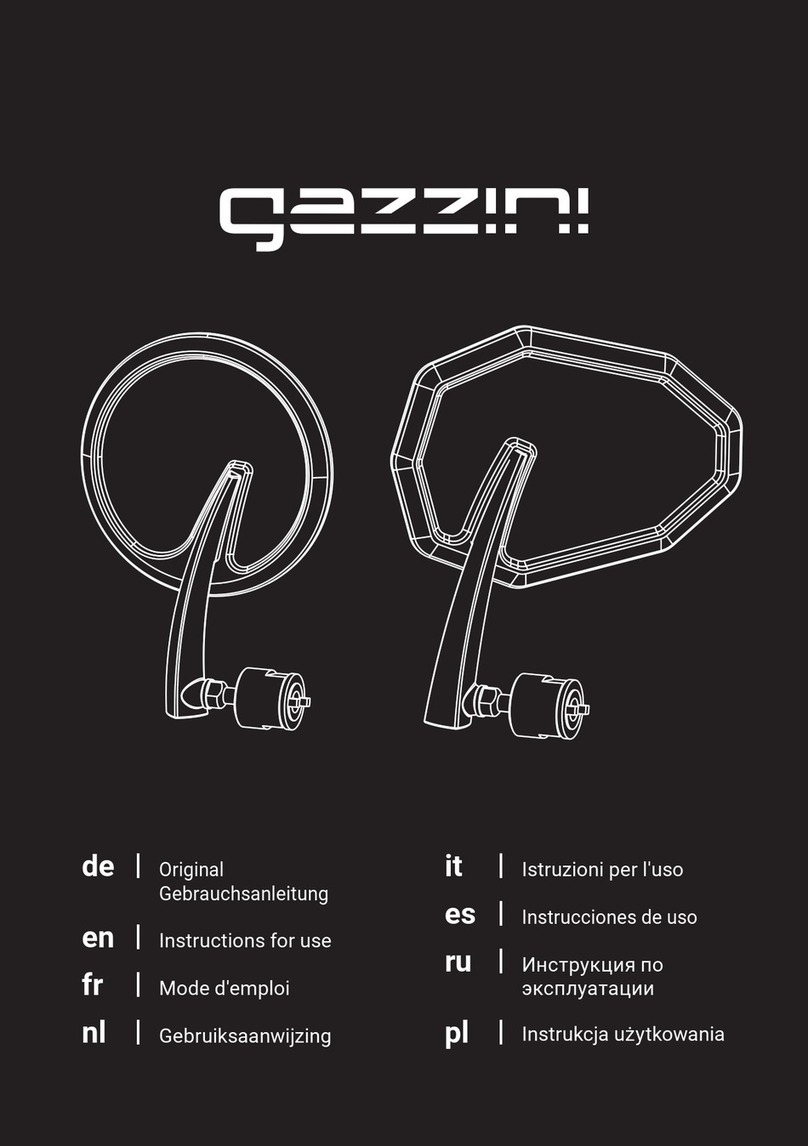
Gazzini
Gazzini 10040695 User manual
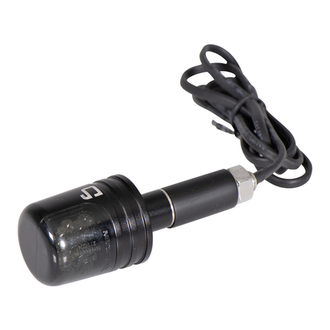
Gazzini
Gazzini 10035349 User manual
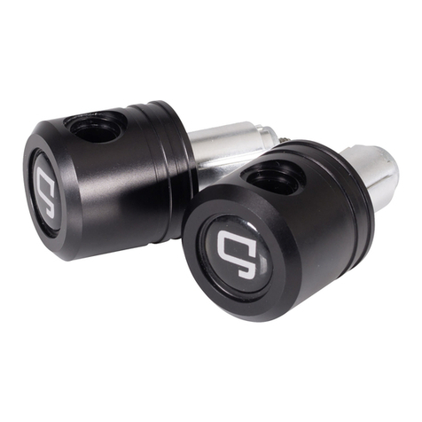
Gazzini
Gazzini 10028739 Operation manual

Gazzini
Gazzini 10040330 User manual
Gazzini
Gazzini 10039625 User manual
Gazzini
Gazzini 10040749 User manual
Gazzini
Gazzini 10040763 User manual
Gazzini
Gazzini 10039180 User manual

Gazzini
Gazzini 10028732 Operating and installation instructions
Gazzini
Gazzini 10030302 User manual
