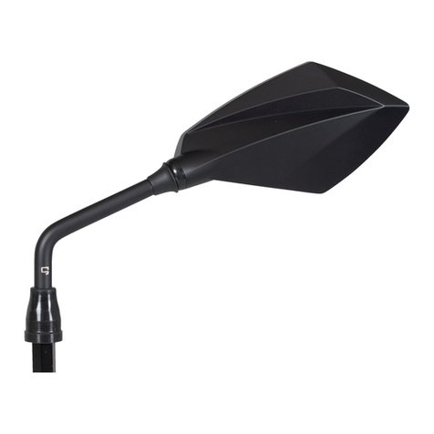
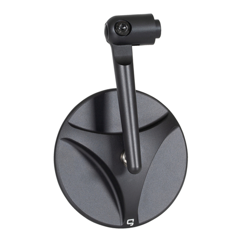
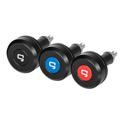
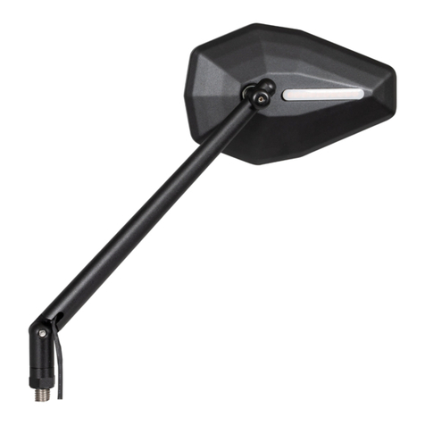
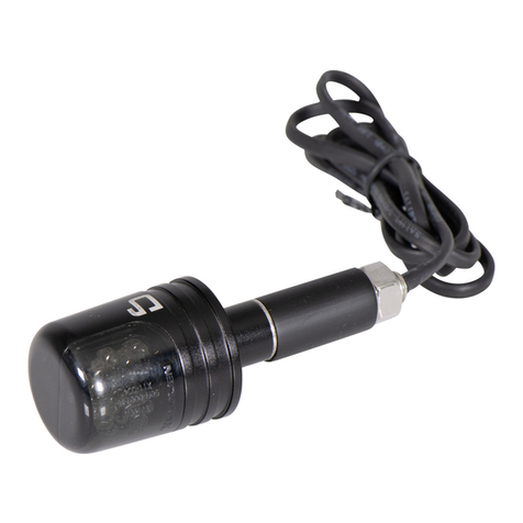
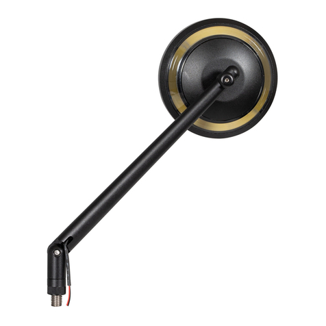
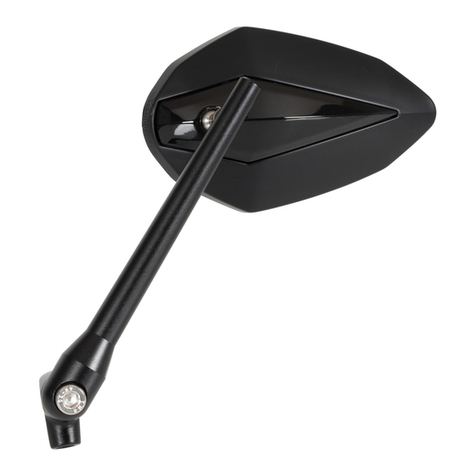
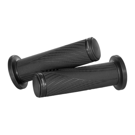
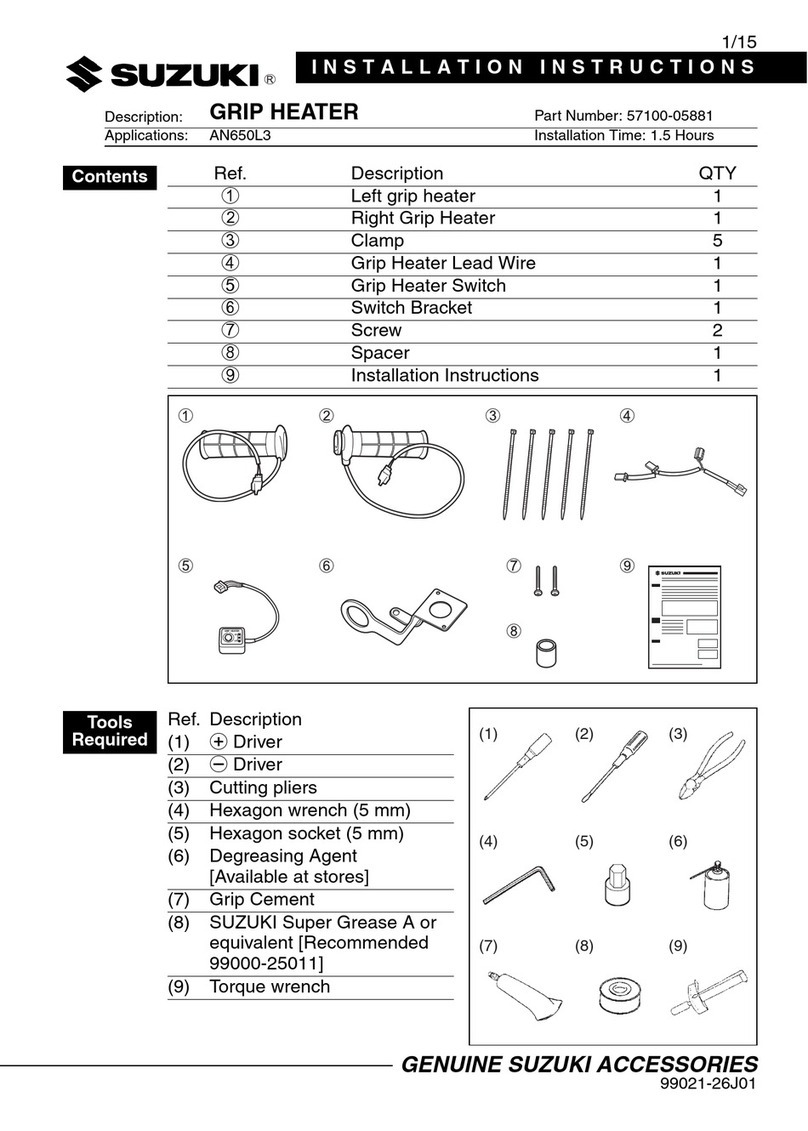
Gazzini 10028739 Operation manual

1
DE|
Original Montage- und
Gebrauchsanweisung
GB|
Original Montage- und
Gebrauchsanweisung
FR |
Original Montage- und
Gebrauchsanweisung
IT
|
Original Montage- und
Gebrauchsanweisung

2
Allgemeines 3
Lieferumfang 3
Warnhinweise 4
Sicherheithinweise 4
Lagerung 4
Montage 4-5
Reinigung und Pflege 5
Entsorgung 5
Gewährleistung 6
Kontakt und Fragen 6
DE |INHALTSVERZEICHNIS

3
DE |ORIGINAL GEBRAUCHS- UND MONTAGEANLEITUNG
LENKERENDEN MIT GELENKAUFNAHME
(Best.Nr. 10028739)
Diese Montageanleitung gehört ausschließlich zu den beschriebenen Produkten. Sie enthält wich-
tige Hinweise zu Anbau, Sicherheit und Gewährleistung. Diese sind stets zu beachten, auch wenn
Sie das Produkt an Dritte weitergeben. Archivieren Sie deshalb diese Gebrauchsanleitung, sodass
Sie zu einem späteren Zeitpunkt erneut darin nachlesen können.
1 | ALLGEMEINES
Die gazzini Lenkerenden mit Gelenkaufnahme dienen zur Montage von Spiegeln aus dem modu-
laren gazzini Spiegelsystem. Sie sind für Motorrad-Rohrlenker mit einem Außendurchmesser von 22
mm (metrisch) bzw. 25,4 mm (zöllig) und einem Innendurchmesser von mindestens 13,5 konzipiert.
Die Enden des Fahrzeuglenkers müssen offen, d.h. sie dürfen nicht von Gewindeeinsätzen o.ä. ver-
sperrt sein. Damit Sie die Komponenten korrekt und sicher an Ihrem Motorrad verwenden können,
beachten Sie bitte unbedingt die folgenden Montage- und Sicherheitshinweise.
2 | LIEFERUMFANG
1| 2| 3| 4|
2x Lenkerende mit Gelenkaufnahme
2x Zylinderschrauben mit Innensechskant
M6 x 60 A2
Gewindestift ISO 4026 M5 x 7 A2
2x Spannhülse (groß & klein)
und Gewindekonus
2x Abdeckkappe (selbstklebend)
4
5
1
2
3
5|

4
3 | WARNHINWEISE
Um die Fahrsicherheit zu gewährleisten, muss das Lenkerende zuverlässig fest im Lenker angebracht
werden – abfallende Lenkerenden können Unfälle im Straßenverkehr verursachen.
4 | SICHERHEITSHINWEISE
Bei Schäden, die durch Nichtbeachtung dieser Montageanleitung verursacht werden,
erlischt der Gewährleistungsanspruch. Für Folgeschäden wird keine Haftung übernommen.
Bei Sach- oder Personenschäden, die durch unsachgemäße Handhabung oder Nichtbeachten
der Sicherheitshinweise verursacht werden, wird keine Haftung übernommen. In solchen Fällen
erlischt der Gewährleistungsanspruch.
Aus Sicherheits- und Zulassungsgründen ist das eigenmächtige Umbauen und/oder Verändern
der Komponenten der gazzini Lenkerenden nicht gestattet.
Da es sich bei den gazzini Lenkerenden um universell einsetzbare Produkte ohne
spezifische Fahrzeugzuordnung handelt, ist es wichtig, dass Sie Sich vor dem ersten Gebrauch
davon überzeugen, dass sich die Komponenten ohne Probleme sachgerecht an Ihrem Fahrzeug
anwenden/verwenden lassen. Achten Sie dabei unbedingt auf die Angaben Ihrer Fahrzeug-
Bedienungsanleitung und die Vorgaben des Fahrzeugherstellers. Dies ist notwendig, da durch
die nicht sach- und typgerechte Verwendung dieser Produkte die Fahrsicherheit und/oder die
Beschaffenheit des Fahrzeuges beeinträchtigt werden können.
Überprüfen Sie die Lenkerenden nach der Montage und vor jeder Fahrt auf festen Sitz.
Achten Sie darauf, dass der Gasgriff freigängig ist und selbstständig zurückschnellen kann.
Halten Sie Plastikfolien oder anderes Verpackungsmaterial fern von Kindern, es besteht
Erstickungsgefahr.
5 | LAGERUNG
Lagern Sie die noch nicht montierten gazzini Lenkerenden in einem vor Witterung und Feuchtigkeit
geschützten geschlossenen Raum in der Original-Verpackung.
6 | MONTAGE
Stecken Sie je eine Zylinderschraube (2) in ein Lenkerende (1) ein, geben Sie die kleinste
Spannhülse (4) darüber und drehen Sie den Konus auf das Gewinde, sodass er die Hülse
leicht aufspreizt. Stecken Sie die Hülse in den offenen Lenker und prüfen Sie, ob auch die
große Spannhülse aus dem Lieferumfang aufgesteckt werden muss, um das Lenkrohr größtmög-
lich auszufüllen. Stecken Sie das Lenkerende nun so in den Lenker, dass die Bohrung für den
Spiegelarm in die gewünschte Position zeigt und ziehen Sie die Zylinderschraube (2) mit einem
Innensechskantschlüssel (Größe: 5) leicht fest. Wiederholen Sie den Vorgang auf der anderen
Lenkerseite. Achten Sie darauf, dass der Gasgriff des Motorrades nicht durch das Lenkerende
blockiert wird. Es sollte ein Zwischenraum von 2 mm zwischen Gasgriff und Lenkerende vorhanden

5
sein. Der Gasgriff muss leicht zu betätigen sein und beim Loslassen selbsttätig zurückschnellen.
Verschieben Sie die Armatur oder das Lenkerende ein wenig, wenn der Gasgriff eingeklemmt wird.
Stecken Sie nun das Spiegelgelenk mit montiertem Spiegelarm und Spiegelgehäuse (gehört nicht
zum Lieferumfang – bitte separat aus dem gazzini Spiegelsystem erwerben) in die Bohrung und
fixieren den Spiegel von der Seite mit dem Gewindestift (3), welchen Sie im Vorwege mit flüssiger
Schraubensicherung (mittelfest) bestreichen. Ist alles wunschgemäß ausgerichtet, ziehen Sie die
Zylinderschrauben (2) der Klemmung gut fest. Montieren Sie den kompletten Spiegel (entsprechend
Ihrer Wunschkonfiguration des gazzini Spiegelsystems) und richten Sie ihn auf dem Motorrad
sitzend aus. Kleben Sie erst nach dem Ausrichten die selbstklebenden gazzini Abdeckkappen (5)
über die Zylinderschraube auf das Lenkerende auf.
7 | REINIGUNG UND PFLEGE
Reinigen Sie die Lenkerenden mit warmer Seifenlauge oder Motorradreiniger und einem weichen
Tuch. Verwenden Sie keine Reiniger, die Aluminium angreifen könnten. Verwenden Sie abschlie-
ßend ein wachshaltiges Pflegemittel, das die Oberfläche gegen Witterungseinflüsse schützt.
8 | ENTSORGUNG
Verpackung entsorgen:
Entsorgen Sie die Verpackung sortenrein. Geben Sie Pappe und Karton zum Altpapier, Folie in die
Wertstoffsammlung.
Lenkerenden entsorgen:
Bedenken Sie bitte, dass viele Komponenten aus wertvollen Rohstoffen bestehen und wiederverwen-
det werden können. Entsorgen Sie die Lenkerenden daher nicht mit dem Hausmüll, sondern führen
Sie sie bitte Ihrer Sammelstelle für Metallschrott zu.

6
9 | GEWÄHRLEISTUNG
Berücksichtigen Sie unbedingt diese Sicherheits- und Montagehinweise. Nehmen Sie sich Zeit
für eine sachgemäße Befestigung. Eine unzureichende oder unsachgemäße Montage oder
Verwendung der Lenkerenden führt zum Erlöschen jeglicher Gewährleistungsansprüche.
10 | KONTAKT UND FRAGEN
Bei Fragen zum Produkt und/oder dieser Anleitung kontaktieren Sie vor der Montage bzw. vor
dem ersten Gebrauch des Produktes unser Technikcenter unter der Faxnummer 040-734 193-58
gemeinsam, dass das Produkt fehlerlos montiert und fehlerlos benutzt wird.
Hergestellt in Bosnien-Herzegowina

7
General information 8
Scope of delivery 8
Warnings 9
Safety instructions 9
Storage 9
Installation 9-10
Cleaning and care 10
Disposal 10
Warranty 10
Contact and questions 11
GB|TABLE OF CONTENTS

8
GB|
TRANSLATION OF ORIGINAL INSTRUCTIONS FOR USE AND INSTALLATION
HANDLEBAR ENDS WITH JOINT MOUNT
(Order no. 10028739)
These instructions for installation and use apply exclusively to the products described. They contain
important information on installation, safety and warranty. You should always follow these instruc-
tions, including if you give the product to someone else. Keep them in a safe place so that you can
refer to them again later.
1 | GENERAL INFORMATION
Gazzini Bar Ends with joint mount are used for installing mirrors from the modular gazzini mirror
system. They are designed for tubular handlebars with an outside diameter of 22 mm (metric) or
25.4 mm (imperial), and with an inside diameter at least 13.5 mm. The motorcycle handlebar must
have open ends, i.e. it must not be blocked by threaded inserts or the like. To ensure that you can
use these components correctly and safely, please observe the installation and safety Instructions.
2 | SCOPE OF DELIVERY
1| 2| 3| 4|
2x handlebar ends with joint mount
2x cheese head screws with hex socket
M6 x 60 A2
Threaded pin ISO 4026 M5 x 7 A2
2x clamping sleeves (large & small) and
weight cones
2x end-caps (self-adhesive)
4
5
1
2
3
5|

9
3 | WARNINGS
To ensure the safety of the vehicle, the handlebar ends must be securely fixed in the handlebars – if
handlebar ends fall off, they could cause a road accident.
4 | SAFETY INSTRUCTIONS
The warranty will be rendered null and void in case of any damage caused by failure to follow
these installation instructions. No liability will be assumed for consequential damage.
We accept no liability for material damage or personal injury caused by improper use or fai-
lure to follow the safety instructions. In such cases, the warranty will be rendered null and void.
For safety reasons and to avoid invalidating official approval, unauthorised modification and/
or changes to the components of the gazzini handlebar ends are not permitted.
Since the gazzini handlebar ends are universal products and are not intended for only one
particular vehicle, it is important to make sure that the components are suitable for your motorcycle
before you use them for the first time. In doing so, always follow the instructions in your vehicle
owner's manual and the directions of the vehicle manufacturer. This is essential, as improper use of
this product or its unsuitability for a vehicle could impair the safety of the vehicle and/or damage it.
Check after installation and before every journey to ensure that the handlebar ends are secure.
Make sure that the throttle twistgrip can move freely and can spring back by itself.
Keep plastic films and other packaging materials away from children. There is a danger of suf-
focation.
5 | STORAGE
Lagern Sie die noch nicht montierten gazzini Lenkerenden in einem vor Witterung und Feuchtigkeit
Until they are installed, the gazzini handlebar ends should be stored in the original packaging in a
closed room that is protected against the weather and moisture.
6 | INSTALLATION
Insert a cheese head screw (2) into one of the handlebar ends (1). Fit the smallest clamping sleeve
over the screw and twist the cone onto the thread so that the sleeve is spread slightly. Insert the
sleeve into the open handlebar and check whether the large clamping sleeve supplied also needs
to be fitted in order to fill out the handlebar tube as completely as possible. Then insert the bar end
into the handlebar so that the hole for the mirror stem points in the desired direction, and gently
tighten the cheese head screw (2) using a hex key (size: 5). Repeat these steps for the other end
of the handlebar. Ensure that the handlebar end does not prevent the throttle twistgrip from turning
freely. There should be 2 mm of free space between the throttle twistgrip and the handlebar end.
The throttle twistgrip must be easy to turn and should spring back by itself when released. Shift the
control or the handlebar end slightly if the throttle twistgrip is impeded. Then fit the mirror joint with
attached mirror stem and housing (not included – please purchase separately from the gazzini mir-

10
ror system) into the hole and fix the mirror from the side with the threaded pin (3), after first coating
the threaded pin with liquid thread lock. When everything is aligned as you want, firmly tighten the
cheese head screws (2) of the clamp. Install the complete mirror (according to your chosen configu-
ration of the gazzini mirror system) and align it with the motorcycle while sitting in the saddle. After
you have aligned the mirror, you can then install the self-adhesive gazzini end-caps over the cheese
head screws and onto the handlebar end.
7 | CLEANING AND CARE
Use warm soapy water or a motorcycle cleaner and a soft cloth for cleaning the handlebar ends.
Do not use a cleaner which could corrode the aluminium. Afterwards, use a wax-based product
which will protect the surfaces against the elements.
8 | DISPOSAL
Packaging disposal:
Please dispose of the packaging appropriately. Dispose of cardboard and cardboard boxes with
waste paper and dispose of plastic film with recyclables.
Handlebar ends disposal:
Please remember that many components are made of valuable raw materials and can be recycled.
Therefore, do not dispose of the handlebar ends with the household waste; take them to your col-
lection point for scrap metal instead.
9 | WARRANTY
Always follow these safety and installation instructions. Allow yourself sufficient time for proper
installation. Incorrect use or installation of the handlebar ends will void all warranty claims.

11
10 | CONTACT AND QUESTIONS
If you have any questions about the product and/or these instructions, please contact our Technical
use the product. We will help you as quickly as possible. This is the best way to ensure that your
product is installed properly and used correctly.
Manufactured in Bosnia and Herzegovina

12
Généralités 13
Équipement fourni 13
Avertissements 14
Consignes de sécurité 14
Stockage 14
Montage 14-15
Nettoyage et entretien 15
Élimination 15
Garantie 16
Contact et questions 16
FR |TABLE DES MATIÈRES

13
FR |TRADUCTION DES INSTRUCTIONS D'UTILISATION ET DE MONTAGE
EMBOUTS DE GUIDON AVEC FIXATION ARTICULEE
(n° de cde 10028739)
Ces instructions de montage correspondent uniquement aux produits décrits. Elles contiennent des
remarques importantes concernant le montage, la sécurité et la garantie. Ces remarques doivent
également êtres observées (et transmises) en cas de cession du produit à un tiers. Archivez par
conséquent le présent mode d'emploi afin de pouvoir le consulter à une date ultérieure.
1 | GENERALITES
Les embouts de guidon gazzini avec fixation articulée servent au montage de rétroviseurs du
système de rétroviseurs modulaires gazzini. Ils sont conçus pour des guidons tubulaires d'un
diamètre extérieur de 22 mm (métriques) ou de 25,4 mm (en pouces) et d'un diamètre intérieur de
du moins 13,5. Les extrémités du guidon doivent être ouvertes, c'est-à-dire non bloquées par des
inserts filetés ou autres. Pour pouvoir utiliser correctement et en toute sécurité ces composants sur
votre moto, veuillez impérativement observer les consignes de sécurité et de montage suivantes.
2 | ÉQUIPEMENT FOURNI
1| 2| 3| 4|
2 embouts de guidon avec fixation articulée
2 vis cylindriques à six pans creux
M6 x 60 A2
Tige filetée ISO 4026 M5 x 7 A2
2 douilles de serrage (grande & petite taille) et
cône fileté
2 capuchons (autoadhésifs)
4
5
1
2
3
5|

14
3 | AVERTISSEMENTS
Pour garantir la sécurité routière, les embouts de guidon doivent être fixés de manière fiable sur le
guidon ; des embouts de guidon qui tombent risquent de provoquer des accidents de la circulation
routière.
4 | CONSIGNES DE SECURITE
En cas de dommages résultant de la non-observation des présentes instructions de montage, le
droit à garantie expire. Nous déclinons toute responsabilité pour les dommages consécutifs.
En présence de dommages matériels ou corporels résultant d'une manipulation incorrecte ou de
la non-observation des consignes de sécurité, nous déclinons toute responsabilité. Dans un tel
cas, le droit à garantie expire.
Pour des raisons liées à la sécurité et à l'homologation, il est interdit de transformer et/ou modi-
fier les composants des embouts de guidon gazzini de manière arbitraire.
Comme les embouts de guidon gazzini sont destinés à un emploi universel et qu'ils ne sont pas
destinés à un type de véhicule précis, il est important que vous vous assuriez, avant leur toute
première utilisation, que vous pouvez les utiliser sur votre véhicule de manière conforme et sans
aucun problème. Observez pour cela impérativement les informations contenues dans le mode
d'emploi de votre véhicule ainsi que les spécifications du constructeur du véhicule. Cela est
nécessaire, car un emploi incorrect ou inapproprié des produits peut nuire à la sécurité routière
et/ou à la qualité du véhicule.
Après le montage et avant chaque déplacement, assurez-vous que les embouts de guidon sont
bien en place.
Assurez-vous que la poignée d'accélérateur reste dégagée et peut revenir automatiquement
dans sa position initiale.
Conservez les films plastiques et autre matériau d'emballage hors de portée des enfants. Risque
d'asphyxie.
5 | STOCKAGE
Stockez les embouts de guidon gazzini pas encore montés dans l'emballage d'origine dans une
pièce fermée à l'abri des intempéries et de l'humidité.
6 | MONTAGE
Insérez une vis cylindrique (2) dans chaque embout de guidon (1). Placez la plus petite douille
de serrage (4) par-dessus et vissez le cône sur le filetage, de manière à élargir légèrement la
douille. Placez la douille dans le guidon ouvert et vérifiez si la grande douille de serrage fournie
doit également être mise en place pour remplir le plus possible le tube de guidon. Placez ensuite
l'embout dans le guidon de manière à ce que l'alésage pour le bras de rétroviseur soit orienté dans
la position souhaitée et serrez légèrement la vis cylindrique (2) avec une clé mâle coudée pour

15
vis à six pans creux (taille 5). Répétez cette opération de l'autre côté du guidon. Assurez-vous que
la poignée d'accélérateur de la moto n'est pas bloquée par l'embout de guidon. Un espace de 2
mm doit exister entre la poignée d'accélérateur et l'embout de guidon. La poignée d'accélérateur
doit pouvoir être actionnée facilement et doit revenir automatiquement lorsqu'elle est relâchée. Si
la poignée d'accélérateur est bloquée, décalez légèrement les cadrans ou l'embout de guidon.
Placez ensuite l'articulation pour rétroviseur dans l'alésage, le bras et le boîtier de rétroviseur (non
fourni, veuillez le commander séparément dans le système de rétroviseurs gazzini) étant montés
et fixez le rétroviseur sur le côté avec la tige filetée (3) (appliquez du freinfilet liquide (résistance
moyenne) sur celle-ci au préalable). Lorsque tous les éléments sont positionnés comme vous le sou-
haitez, serrez fermement la vis cylindrique (2) de la fixation. Montez le rétroviseur complet (selon
la configuration du système de rétroviseurs gazzini que vous souhaitez) et orientez-le sur la moto en
position assise. Collez les capuchons autoadhésifs gazzini (5) sur l'embout de guidon par-dessus la
vis cylindrique seulement après avoir orienté le rétroviseur.
7 | NETTOYAGE ET ENTRETIEN
Nettoyez les embouts de guidon à l'eau savonneuse chaude ou avec un nettoyant moto et un
chiffon doux. N'utilisez pas de produit nettoyant pouvant attaquer l'aluminium. Pour finir, utilisez un
produit d'entretien à base de cire pour protéger la surface contre les intempéries.
8 | ÉLIMINATION
Élimination de l'emballage :
Éliminez l'emballage en procédant au tri sélectif. Éliminez le papier et le carton avec le papier
destiné au recyclage et le film plastique dans la poubelle appropriée.
Élimination des embouts de guidon :
N'oubliez pas qu'un grand nombre des composants sont fabriqués à partir de matières premières
précieuses et qu'ils peuvent être réutilisés. Ne jetez donc pas les embouts de guidon à la poubelle,
mais déposez-les dans un point de collecte de ferraille.

16
9 | GARANTIE
Respectez impérativement les présentes consignes de sécurité et de montage. Prenez du temps
pour fixer correctement les embouts. Une utilisation ou un montage incorrects ou inappropriés des
embouts de guidon annule tout droit à garantie.
10 | CONTACT ET QUESTIONS
Pour toutes questions concernant le produit et/ou le présent mode d'emploi, veuillez contacter,
avant le montage ou la première utilisation du produit, notre Centre technique par fax au numéro
les plus brefs délais. De cette manière, nous garantissons ensemble un montage et une utilisation
irréprochables du produit.
Fabriqué en Bosnie-Herzégovine

17
Informazioni generali 18
Contenuto della fornitura 18
Avvertenze 19
Istruzioni per la sicurezza 19
Stoccaggio 19
Montaggio 19-20
Pulizia e cura 20
Smaltimento 20
Garanzia 21
Contatti e domande 21
IT |INDICE

18
IT |DUZIONE DELLE ISTRUZIONI DI MONTAGGIO E PER L'USO
ESTREMITÀ DEL MANUBRIO CON ATTACCO DELLO SNODO
(Cod. art. 10028739)
Queste istruzioni di montaggio appartengono esclusivamente ai prodotti descritti. Contengono
informazioni importanti per il montaggio, la sicurezza e la garanzia. Devono essere sempre
osservate, anche quando il prodotto viene consegnato a terzi. Custodire quindi queste istruzioni per
l'uso in modo che possano essere consultate anche in un momento successivo.
1 | INFORMAZIONI GENERALI
Le estremità del manubrio con attacco dello snodo servono per il montaggio degli specchietti
retrovisori del relativo sistema modulare gazzini e sono state concepite per manubri tubolari da
moto con diametro esterno di 22 mm (metrico) o 25.4 mm (in pollici) e diametro interno compreso
fra 10/5000 almeno 13,5 mm. Le estremità del manubrio del veicolo devono essere aperte,
ovvero non bloccate da inserti filettati o simili. Attenersi assolutamente alle seguenti istruzioni di
montaggio e per la sicurezza per un utilizzo corretto e sicuro dei componenti sulla moto.
2 | CONTENUTO DELLA FORNITURA
1| 2| 3| 4|
2 estremità del manubrio con attacco dello snodo
2 viti a testa cilindrica con cava esagonale
M6 x 60 A2
Grano ISO 4026 M5 x 7 A2
2 bussole di serraggio (grande e piccola)
e coni filettati
2 tappi (autoadesivi)
4
5
1
2
3
5|

19
3 | AVVERTENZE
Per garantire la sicurezza alla guida, l'estremità del manubrio deve essere fissata in maniera salda
e sicura al manubrio poiché la sua caduta può provocare incidenti stradali.
4 | ISTRUZIONI PER LA SICUREZZA
In caso di danni dovuti alla mancata osservanza delle presenti istruzioni di montaggio decade il
diritto di garanzia. Si declina ogni responsabilità per danni conseguenti.
Si declina ogni responsabilità per danni a persone o cose dovuti a una movimentazione
impropria o alla mancata osservanza delle istruzioni per la sicurezza. In questi casi decade il
diritto di garanzia.
Per motivi di sicurezza e di omologazione non è consentito effettuare conversioni e/o modifiche
ai componenti delle estremità del manubrio gazzini.
Dato che le estremità del manubrio gazzini sono prodotti a impiego universale senza
destinazione specifica del veicolo, è importante essere certi prima del primo utilizzo che i
componenti possano essere montati/utilizzati in modo corretto sul proprio veicolo senza alcun
problema. Osservare assolutamente le indicazioni contenute nelle istruzioni per l'uso del proprio
veicolo e alle specifiche del costruttore del veicolo. Questo è essenziale in quanto un utilizzo
del prodotto improprio o non corretto per il tipo può pregiudicare la sicurezza di guida e/o le
caratteristiche del veicolo.
Dopo il montaggio e prima di ogni guida, controllare che le estremità del manubrio siano fissate
saldamente.
Assicurarsi che la manopola dell'acceleratore sia accessibile e in grado di scattare indietro
automaticamente.
Tenere lontano i bambini da pellicole di plastica o altro materiale di imballaggio, pericolo di
soffocamento.
5 | STOCCAGGIO
Conservare le estremità del manubrio gazzini non ancora montate nella confezione originale in un
luogo chiuso e protteto da intemperie e umidità.
6 | MONTAGGIO
Inserire una vite a testa cilindrica (2) in ciascuna estremità del manubrio (1), quindi inserirvi
sopra la bussola di serraggio più piccola (4) e ruotare il cono sul filetto in modo da provocare
un lieve dilatamento della bussola. Inserire la bussola nel manubrio aperto e verificare se per
riempire il più possibile l'asta del manubrio occorre anche la bussola di serraggio grande inclusa
nella fornitura. Inserire ora l'estremità del manubrio nel manubrio in modo che il foro per il
braccio specchietto sia nella posizione desiderata e serrare la vite a testa cilindrica (2) con una
chiave a brugola (misura 5). Ripetere la procedura sull'altro lato del manubrio. Fare attenzione

20
che la manopola dell'acceleratore della moto non venga bloccata dall'estremità del manubrio.
Mantenere una distanza di 2 mm tra la manopola dell'acceleratore e l'estremità del manubrio.
La manopola dell'acceleratore deve essere semplice da azionare e, quando rilasciata, scattare
indietro automaticamente. Se la manopola dell'acceleratore è incastrata, spostare leggermente il
comando o l'estremità del manubrio. Inserire nel foro lo snodo dello specchietto retrovisore con
braccio e alloggiamento premontati (quest'ultimo non è compreso nella fornitura e deve essere
acquistato separatamente dal sistema gazzini) e fissare lo specchietto dal lato con il grano (3)
precedentemente spennellato con frenafiletti liquido (medio solido). Se tutto è posizionato come
desiderato, serrare saldamente le viti a testa cilindrica (2) del bloccaggio. Montare lo specchietto
retrovisore completo (in base alla configurazione desiderata del sistema di specchietti retrovisori
gazzini) e direzionarlo una volta seduti sulla moto. Dopo avere direzionato lo specchietto
retrovisore, applicare i tappi autoadesivi gazzini (5) sulla vite a testa cilindrica posta sull'estremità
del manubrio.
7 | PULIZIA E CURA
Pulire le estremità del manubrio con acqua saponata calda o con un detergente per moto e
un panno morbido. Non utilizzare detergenti che potrebbero risultare aggressivi sull'alluminio.
Utilizzare infine un prodotto a base di cera in grado di proteggere la superficie dagli agenti
atmosferici.
8 | SMALTIMENTO
VSmaltimento della confezione:
Smaltire la confezione in base al tipo di materiale. Mettere il cartone nella raccolta della carta e la
pellicola in quella del materiale riciclabile.
Smaltimento delle estremità del manubrio:
Tenere presente che molti componenti sono costituiti da materie prime di pregio e possono dunque
essere riutilizzati. Pertanto non smaltire le estremità del manubrio nei rifiuti domestici, bensì portarle
al proprio centro di raccolta per i rottami metallici.
Table of contents
Languages:
Other Gazzini Motorcycle Accessories manuals

Gazzini
Gazzini 10020889 Guide

Gazzini
Gazzini 10040330 User manual

Gazzini
Gazzini 10039294 User manual

Gazzini
Gazzini 10040761 User manual

Gazzini
Gazzini 10040695 User manual

Gazzini
Gazzini 10039290 User manual

Gazzini
Gazzini 10030302 User manual

Gazzini
Gazzini 10028731 User manual

Gazzini
Gazzini 10030234 User manual

Gazzini
Gazzini 10029447 User manual

Gazzini
Gazzini 10040763 User manual

Gazzini
Gazzini 10039180 User manual

Gazzini
Gazzini 10039621 User manual

Gazzini
Gazzini 10013450 User manual

Gazzini
Gazzini 10028732 Operating and installation instructions

Gazzini
Gazzini 10040749 User manual

Gazzini
Gazzini 10039625 User manual

Gazzini
Gazzini 10035349 User manual