manuals.online logo
Brands
  1. Home
  2. •
  3. Brands
  4. •
  5. GE
  6. •
  7. Circuit Breaker
  8. •
  9. GE PowerVac 5kV VL User manual

GE PowerVac 5kV VL User manual

Other GE Circuit Breaker manuals

GE AM-13.8-750-5 User manual

GE

GE AM-13.8-750-5 User manual

GE Power Break II SPUV012DC User manual

GE

GE Power Break II SPUV012DC User manual

GE EntelliGuard G User manual

GE

GE EntelliGuard G User manual

GE AK-1-15 Series Owner's manual

GE

GE AK-1-15 Series Owner's manual

GE Rapid TripFix User manual

GE

GE Rapid TripFix User manual

GE EntelliGuard GBKRKR User manual

GE

GE EntelliGuard GBKRKR User manual

GE AKR-75 Series Programming manual

GE

GE AKR-75 Series Programming manual

GE Spectra Series AMCB6FGB User manual

GE

GE Spectra Series AMCB6FGB User manual

GE PowerVac User manual

GE

GE PowerVac User manual

GE A Series Pro-Stock THQB User manual

GE

GE A Series Pro-Stock THQB User manual

GE AM-4.16-250-6C User manual

GE

GE AM-4.16-250-6C User manual

GE MicroVersaTrip Plus Series User manual

GE

GE MicroVersaTrip Plus Series User manual

GE GL 310 F3/4031 P/VR User manual

GE

GE GL 310 F3/4031 P/VR User manual

GE EntelliGuard GT-H User manual

GE

GE EntelliGuard GT-H User manual

GE AKR-30S User manual

GE

GE AKR-30S User manual

GE SecoVac Series User manual

GE

GE SecoVac Series User manual

GE AK-1-15 Series User manual

GE

GE AK-1-15 Series User manual

GE MicroVersaTrip AKR-75 User manual

GE

GE MicroVersaTrip AKR-75 User manual

GE Power-Break TSUV1 User manual

GE

GE Power-Break TSUV1 User manual

GE Power Break II User manual

GE

GE Power Break II User manual

GE EntelliGuard R7 User manual

GE

GE EntelliGuard R7 User manual

GE AM-4.16-250-6 User manual

GE

GE AM-4.16-250-6 User manual

GE AM-2.4/4.16-100/150- 3 User manual

GE

GE AM-2.4/4.16-100/150- 3 User manual

GE SD200SA User manual

GE

GE SD200SA User manual

Popular Circuit Breaker manuals by other brands

Siemens 3VT9524-4TG30 quick start guide

Siemens

Siemens 3VT9524-4TG30 quick start guide

Acrel ASCB1 Series Installation and operation manual

Acrel

Acrel ASCB1 Series Installation and operation manual

ABB SACE Emax 2 E2.2 manual

ABB

ABB SACE Emax 2 E2.2 manual

Eaton NOVA LBS 15 Installation and operation instructions

Eaton

Eaton NOVA LBS 15 Installation and operation instructions

ABB SACE Emax E1 quick start guide

ABB

ABB SACE Emax E1 quick start guide

Siemens SIRIUS 3RV1742 Original operating instructions

Siemens

Siemens SIRIUS 3RV1742 Original operating instructions

WEG FHU ACW125 installation instructions

WEG

WEG FHU ACW125 installation instructions

TERASAKI NHP TemBreak PRO P160 Series installation instructions

TERASAKI

TERASAKI NHP TemBreak PRO P160 Series installation instructions

Siemens Sentron 3VA9157-0PK1 Series operating instructions

Siemens

Siemens Sentron 3VA9157-0PK1 Series operating instructions

hager TS 303 User instruction

hager

hager TS 303 User instruction

ETI EFI-4B Instructions for mounting

ETI

ETI EFI-4B Instructions for mounting

Gladiator GCB150 Installation instruction

Gladiator

Gladiator GCB150 Installation instruction

nader NDM3EU-225 operating instructions

nader

nader NDM3EU-225 operating instructions

Eaton 50DHP-VR Instruction handbook

Eaton

Eaton 50DHP-VR Instruction handbook

ABB SACE Emax 2 E6.2 Instruction handbook

ABB

ABB SACE Emax 2 E6.2 Instruction handbook

Gewiss 90 RCD Installation

Gewiss

Gewiss 90 RCD Installation

OEZ LFN Instructions for use

OEZ

OEZ LFN Instructions for use

Eaton Power Defense PDG2 Instruction leaflet

Eaton

Eaton Power Defense PDG2 Instruction leaflet

manuals.online logo
manuals.online logoBrands
  • About & Mission
  • Contact us
  • Privacy Policy
  • Terms and Conditions

Copyright 2025 Manuals.Online. All Rights Reserved.

1
GE PowerVac®5kV VL
for PowerVac®Vacuum Circuit Breakers
Type PV VL 4.16-250-0
with ML-19 Mechanism
Instructions
DEH 40012
g
Courtesy of NationalSwitchgear.com
2
DEH-40012
WARNINGS, CAUTIONS AND NOTES
AS USED IN THIS PUBLICATION
This document is based on information available at the time of this publication. While efforts have
been made to ensure accuracy, the information contained herein does not cover all details or varia-
tions in hardware and software, nor does it provide for every possible contingency in connection
with installation, operation, and maintenance. Features may be described herein that are not
present in all hardware and software systems. GE Industrial Systems assumes no obligation of
notice to holders of this document with respect to changes subsequently made.
WARNINGS Warningnoticesareusedin this publicationtoemphasize that hazardousvoltages,
currents, or other conditions that could cause personal injury or death are present
in this equipment or may be associated with its use.
Warning notices are also used for situations in which inattention or lack of equip-
mentknowledgecould cause either personal injuryor damage to equipment.
CAUTIONS Caution notices are used for situations in which equipment might be damaged if
care is not taken.
NOTES Notes call attention to information that is especially significant to understanding
andoperatingthe equipment.
GEIndustrialSystemsmakesno representation or warranty, expressed,implied,or statutory, with
respect to, and assumes no responsibility for the accuracy completeness, sufficiency, or useful-
ness of the information contained herein. No warranties of merchantability or fitness for purpose
shall apply.
The following is a trademark of GE Company: PowerVac®
©2000GE Company
AllRightsReserved
Courtesy of NationalSwitchgear.com
PowerVac®5kV Vertical Lift
Table of Contents
3
Chapter 1. Introduction
1-1 Safety ...................................................................................................................... 6
1-2 Maintenance ........................................................................................................... 6
Chapter 2. Description....................................................................................................................7
Chapter 3. Receiving, Handling & Storage
3-1 Receiving................................................................................................................ 8
3-2 Handling ..................................................................................................................8
3-3 Storage ....................................................................................................................8
3-4 SafetyPrecautions ..................................................................................................8
3-5 UnpackingtheBreaker ............................................................................................8
3-6 SafetyInterlocks ......................................................................................................9
PositiveInterlockSystem .......................................................................................9
Interference Bolts .................................................................................................. 10
Chapter 4. Installation
4-1 Breaker Preparation............................................................................................... 11
4-2 EquipmentTest Position ....................................................................................... 11
4-3 PositiveInterlock System .................................................................................... 11
4-4 Checkingfor Proper Interlock ...............................................................................12
4-5 PrimaryContact Penetration ................................................................................. 14
4-6 Stationary Auxiliary Switch (MOC) ....................................................................... 16
4-7 Stops......................................................................................................................16
4-8 Ground...................................................................................................................16
4-9 SecondaryCoupler................................................................................................ 17
4-10 Position Switch ..................................................................................................... 17
Chapter 5. Operation
5-1 Description ............................................................................................................ 18
5-2 Close Spring Charging ....................................................................................... 19
5-3 Trip-FreeOperation .............................................................................................. 20
5-4 ClosingOperation .................................................................................................20
5-5 OpeningOperation................................................................................................ 21
Chapter 6. Control Circuit
6-1 Typical Wiring Controls ........................................................................................22
Chapter 7. Mechanical Check and Slow Close
7-1 Visual Inspection .................................................................................................. 25
7-2 Closing Spring Charging ...................................................................................... 25
7-3 Closing Spring Gag ..............................................................................................25
7-4 Slow Closing......................................................................................................... 25
7-5 GagTool Removal .................................................................................................25
Chapter 8. Dimensional Checks
8-1 PrimaryContact Erosion ....................................................................................... 26
8-2 Spring Wipe Indicator ..........................................................................................26
8-3 ContactGap ........................................................................................................... 27
Courtesy of NationalSwitchgear.com
PowerVac®5kV Vertical Lift
Table of Contents
4
Chapter 9. Electrical Checks
9-1 ElectricalOperation............................................................................................... 28
9-2 HighPotential Test ................................................................................................ 28
Primary Circuit....................................................................................................... 28
SecondaryCircuit.................................................................................................. 28
9-3 Primary Circuit Resistance.................................................................................... 28
9-4 Vacuum IntegrityTest............................................................................................ 28
9-5 Insulation Tests ..................................................................................................... 29
Chapter 10. Maintenance
10-1 General .................................................................................................................. 30
10-2 Service Conditions................................................................................................ 31
10-3 Fault Interruptions ................................................................................................. 31
10-4 Contact Erosion ..................................................................................................... 31
10-5 Transfer FingerWear............................................................................................. 31
10-6 Mechanism ............................................................................................................ 31
10-7 PrimaryInsulation Parts ........................................................................................ 31
10-8 Lubrication ............................................................................................................ 32
10-9 RecommendedMaintenance ................................................................................ 32
10-10 BreakerTiming andSpeed Check ........................................................................ 32
Chapter 11. Mechanical Adjustments
11-1 General .................................................................................................................. 35
11-2 WipeAdjustment................................................................................................... 35
11-3 ContactGapAdjustment....................................................................................... 36
11-4 Trip Coil Plunger ................................................................................................... 37
11-5 Close Coil Plunger ................................................................................................ 38
11-6 Control Switch Adjustment .................................................................................. 39
11-7 Adjustment of MOC Switch .................................................................................. 39
11-8 PositiveInterlock................................................................................................... 40
Chapter 12. Repair and Replacement
12-1 General .................................................................................................................. 44
12-2 Replacing Interrupters ........................................................................................... 44
12-3 Primary Bushing.................................................................................................... 45
12-4 Mechanism ............................................................................................................ 45
12-5 Control Switches................................................................................................... 45
12-6 Trip Coil Replacement .......................................................................................... 45
12-7 Closing Coil Replacement .................................................................................... 47
12-8 Auxiliary SwitchReplacement.............................................................................. 47
12-9 MotorReplacement ............................................................................................... 49
12-10 “Y” Relay Replacement ........................................................................................ 49
Chapter 13. Renewal Parts
13-1 Ordering Instructions ............................................................................................ 51
Chapter 14. Stationary Cubicle Subassembly
14-1 Introduction ........................................................................................................... 53
14-2 MajorComponents ............................................................................................... 53
14-3 Testing and Inspection.......................................................................................... 54
14-4 CompartmentMaintenance................................................................................... 58
Courtesy of NationalSwitchgear.com
PowerVac®5kV Vertical Lift
Table of Contents
5
List of Figures
1. View of the 5kV ‘VL’ Breaker with Front Cover ............................................................................... 7
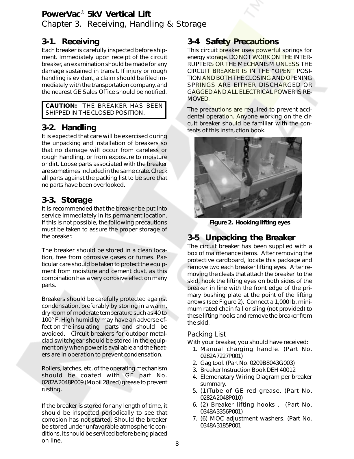
2. Hookinglifting eyes ........................................................................................................................... 8
3. ManualTrip & Close .......................................................................................................................... 9
4. PositiveInterlock ............................................................................................................................... 9
5. Rating Interference Bolt .................................................................................................................. 10
6. Positive Interlock system ................................................................................................................ 12
7. Manual charge handle ..................................................................................................................... 13
8. Primary Contact Insertion ............................................................................................................... 14
9. Primary contact penetration and wipe ........................................................................................... 15
10. MOCswitch ...................................................................................................................................... 16
11. Secondarydisconnect coupler........................................................................................................ 17
12. Front View of ML-19 Mechanism with Front Cover Removed ..................................................... 18
13. Charging & Trip system left side view ............................................................................................ 19
14. Manual Charging system right side view .......................................................................................19
15. Electrical Charging system right side view .................................................................................... 20
16. Closing linkageleft side view.......................................................................................................... 20
17. Opening spring & auxiliary switch left side view ........................................................................... 21
18. Wipe Spring assembly left side view ............................................................................................. 21
19. Typical ML-19mechanisminternalwiring connections ................................................................ 22
20. Typical breaker wiring diagram (Replacement for breakers with MS mechanisms................... 23
21. Typical breaker wiring diagram (Replacement for breakers with ML mechanisms ................... 24
22. Closing spring withgagtool inserted ............................................................................................. 25
23. Contact ErosionIndicator ................................................................................................................ 26
24. Primary contact erosion measurement-rear view ........................................................................ 26
25. Wipe indicator check and wipe measurement-rear view ............................................................. 27
26. Sample Operating Speed Graphs .................................................................................................. 33
27. Opening SpeedAdjustment............................................................................................................ 33
28. Travel Transducer Installation (Part#0144D1235G00X)............................................................... 34
29. Wipe Insulator.................................................................................................................................. 35
30. Contact GapAdjustment—OpeningBuffer.................................................................................... 36
31. Contact Gap measurement, wipe indicator check and wipe measurement ................................ 36
32. Trip coil gapadjustment .................................................................................................................. 37
33. Tripcoil buttonwithgage ................................................................................................................ 37
34. Tripcoilassembly ............................................................................................................................ 37
35. Close coilassembly-frontview ....................................................................................................... 38
36. Close coil gapadjustment-front view ............................................................................................. 38
37. SM/LS & CHG switch adjustment-left side view............................................................................ 39
38. CL/MS andpositiveInterlock switchadjustment-right sideview ................................................. 39
39. Positive Interlock ............................................................................................................................. 40
40. Adjustment of MOCSwitch/PlungerInterlock................................................................................ 41
41. Toggle Linkage Positions ................................................................................................................. 42
41A ToggleLinkagePositions (ViewfromRight Side) .......................................................................... 42
42. Toggle Linkage Positions(Viewfrom Right Side) .......................................................................... 42
42A ToggleLinkagePositions (ViewfromRight Side) .......................................................................... 42
43. Pole Assembly ................................................................................................................................. 44
44. TripCoiland Linkage(ClosingSpring Removed) .......................................................................... 46
45. Front View of ML-19 Breaker Mechanism (Lower)....................................................................... 48
46. Front View of ML-19 Breaker Mechanism (Upper) ....................................................................... 49
47. Motor Cutoff Switch ........................................................................................................................ 50
48. ClosingSpringGag .......................................................................................................................... 50
49. Front View of ML-19 Mechanism with Front Cover Removed ..................................................... 51
50. Schematic of ML-19 Mechanism .................................................................................................... 52
51. Typical stationary structure wiring ................................................................................................. 56
52. Electrical schematic diagram for vertical lift elevating mechanism ............................................ 57
53. Positive interlock M-26 units ........................................................................................................... 59
Appendix A .............................................................................................................................................. 63
List of Tables
1. Measurements .................................................................................................... 43
2. Adjustments........................................................................................................ 43
3. ML-19 Control Devices and Voltages................................................................ 47
4. Elevating Motor Troubleshooting...................................................................... 57
Trouble Reporting Form.......................................................................................... 66-67
Courtesy of NationalSwitchgear.com
6
PowerVac®5kV Vertical Lift
Chapter 1. Introduction
1-1 Safety
IT IS IMPERATIVE THAT ALL PERSONNEL
ASSOCIATEDWITHTHISEQUIPMENTREAD
AND COMPLETELY UNDERSTAND THE
WARNINGS LOCATEDTHROUGHOUTTHIS
INSTRUCTION BOOK. FAILURE TO DO SO
CANRESULTINDAMAGETOPROPERTYOR
PERSONALINJURY.
Each user must maintain a safety program for
the protection of personnel, as well as other
equipment, from the potential hazards associ-
atedwithelectricalequipment.
Thefollowingrequirementsareintendedtoaug-
ment the user’s safety program but NOT sup-
plant the user’s responsibility for devising a
complete safety program. The following basic
industry practiced safety requirements are ap-
plicable to all major electrical equipment such
asswitchgearor switchboards. GEneithercon-
donesnorassumesany responsibility for prac-
tices which deviate from the following:
1. ALL CONDUCTORS MUST BE ASSUMED
TOBEENERGIZEDUNLESSTHEIRPOTEN-
TIAL HAS BEEN MEASURED AS TO
GROUND.
Many accidents have been caused by
powersystemback feedsfrom awidevari-
ety of sources.
2. It is strongly recommended that all equip-
mentbecompletelyde-energized,verified
tobe“dead”,thengroundedwithadequate
capacitygroundingassembliespriortoany
maintenance. Thegroundingcableassem-
bliesmustbeable to withstand energizing
fault levels so that protective equipment
mayclearthe circuitsafely. Additional dis-
cussionon thisconceptiscoveredin Chap-
ter20ofANSI/NFPA70B,Electrical Equip-
mentMaintenance.
3. Althoughinterlockstoreduce some of the
risksareprovided, the individual’sactions
while performing service or maintenance
are essential to prevent accidents. Each
person’sknowledge;hismentalawareness;
and his planned and executed actions of-
ten determine if an accident will occur.
The most important method ofavoiding
accidents is for all associated personnel
to carefully apply a thorough understand-
ingofthespecificequipmentfromtheview-
points of its purpose, its construction, its
operation and the situations which could
behazardous.
1-2 Maintenance
All personnel associated with installation, op-
eration and maintenance of electrical equip-
ment,suchaspower circuit breakers and other
powerhandlingequipment,mustbethoroughly
instructed, with periodic retraining, regarding
powerequipmentingeneralaswellasthe par-
ticular model of equipment on which they are
working. Instruction books, actual devices and
appropriate safety and maintenance practices
such as OSHA publications, National Electric
Safety Code (ANSI C2), and National Fire Pro-
tectionAssociation (NFPA)70BElectricalEquip-
mentMaintenancemust becloselystudiedand
followed. During actual work, supervision
should audit practices to assure conformance.
Courtesy of NationalSwitchgear.com
7
2-1 Description
The PowerVac®5kV VL vacuum circuit breaker
isaverticallift,removableand interchangeable
interrupting element, for use in metal-clad
switchgeartoprovide protectionand control of
electrical apparatus and power systems. The
PowerVac 5kV VL Type PV-VL1 circuit breaker
with ML-19 mechanism is available in continu-
ous current ratings of 1200 and 2000 amperes
in accordance with industry standards.
PowerVac®5kV Vertical Lift
Chapter 2. Description
Referto thebreaker nameplatefor completerat-
ing information of any particular breaker. The
nameplatealsodescribesthe control power re-
quirements for that breaker. The application of
a breaker must be such that its voltage, current
and interrupting ratings are never exceeded.
Since this book is written to include all ratings
of the breaker, as well as several design varia-
tions, the instructions will be of a general char-
acter and all illustrations will be typical unless
otherwisespecified.
1 Nameplate 5 Charge/DischargeIndicator 9 ManualChargeLever
2 CoverMountingBolts 6 Counter 10 SecondaryCoupler
3 FrontRemovableCover 7 ManualTripButton 11 PositiveInterlockRoller
4 Open/CloseIndicator 8 ManualCloseButton 12 PlungerInterlock(MOC)
13 PrimaryBushings (1200Ampshown)
3
Figure 1. View of 5kV ‘VL’ Breaker with Front Cover
Courtesy of NationalSwitchgear.com
8
PowerVac®5kV Vertical Lift
Chapter 3. Receiving, Handling & Storage
3-1. Receiving
Eachbreakeris carefully inspected beforeship-
ment. Immediately upon receipt of the circuit
breaker, anexaminationshouldbemade forany
damage sustained in transit. If injury or rough
handling is evident, a claim should be filed im-
mediatelywith thetransportationcompany,and
the nearest GE Sales Office should be notified.
CAUTION: THE BREAKER HAS BEEN
SHIPPED IN THE CLOSED POSITION.
3-2. Handling
It is expected that care will be exercised during
the unpacking and installation of breakers so
that no damage will occur from careless or
rough handling, or from exposure to moisture
or dirt. Loose parts associated with the breaker
aresometimesincludedinthesamecrate.Check
all parts against the packing list to be sure that
noparts have been overlooked.
3-3. Storage
It is recommended that the breaker be put into
service immediately in its permanent location.
Ifthisisnot possible, the followingprecautions
must be taken to assure the proper storage of
thebreaker.
The breaker should be stored in a clean loca-
tion, free from corrosive gases or fumes. Par-
ticularcareshouldbetaken toprotecttheequip-
ment from moisture and cement dust, as this
combinationhas averycorrosiveeffecton many
parts.
Breakers should be carefully protected against
condensation, preferably by storing in a warm,
dryroomofmoderate temperaturesuchas 40to
100° F. High humidity may have an adverse ef-
fect on the insulating parts and should be
avoided. Circuit breakers for outdoor metal-
clad switchgear should be stored in the equip-
mentonlywhenpowerisavailableandtheheat-
ers are in operation to prevent condensation.
Rollers,latches,etc.oftheoperatingmechanism
should be coated with GE part No.
0282A2048P009(Mobil28red)greasetoprevent
rusting.
If the breaker is stored for any length of time, it
should be inspected periodically to see that
corrosion has not started. Should the breaker
be stored under unfavorable atmospheric con-
ditions,itshouldbeservicedbeforebeingplaced
on line.
Figure 2. Hooking lifting eyes
3-4 Safety Precautions
This circuit breaker uses powerful springs for
energystorage.DONOT WORKON THEINTER-
RUPTERS OR THE MECHANISM UNLESS THE
CIRCUIT BREAKER IS IN THE “OPEN” POSI-
TIONAND BOTHTHECLOSING ANDOPENING
SPRINGS ARE EITHER DISCHARGED OR
GAGGEDAND ALLELECTRICALPOWERIS RE-
MOVED.
The precautions are required to prevent acci-
dental operation. Anyone working on the cir-
cuit breaker should be familiar with the con-
tents of this instruction book.
3-5 Unpacking the Breaker
The circuit breaker has been supplied with a
box of maintenance items. After removing the
protective cardboard, locate this package and
removetwoeachbreakerlifting eyes. After re-
movingthecleats thatattachthebreaker to the
skid, hook the lifting eyes on both sides of the
breaker in line with the front edge of the pri-
mary bushing plate at the point of the lifting
arrows (see Figure2). Connect a 1,000 lb.mini-
mum rated chain fall or sling (not provided) to
theselifting hooksandremovethebreakerfrom
the skid.
Packing List
Withyour breaker, you should have received:
1. Manual charging handle. (Part No.
0282A7227P001)
2. Gagtool. (PartNo. 0209B8043G003)
3. Breaker Instruction BookDEH40012
4. Elemenatary Wiring Diagram per breaker
summary.
5. (1)Tube of GE red grease. (Part No.
0282A2048P010)
6. (2) Breaker lifting hooks . (Part No.
0348A3356P001)
7. (6) MOC adjustment washers. (Part No.
0348A3185P001
Courtesy of NationalSwitchgear.com
9
CAUTION: THE CIRCUIT BREAKER HAS
BEEN SHIPPED IN THE CLOSED POSITION.
After removing packing material, open the
breakerby pushing in firmlyon the manualtrip
button (Figure2, Item8),whilekeepinghands
awayfrommovingparts. A safe way to do this
istopush on thetripbuttonwith the round side
of the maintenaince handle. Verify that the op-
eration counter advances one count.
Closing and opening springs are now in their
discharged positions. Check this by first press-
ing the manual close button, then the manual
trip button. The indicator flags on the front of
the breaker should show “OPEN” and
“DISCHGD”.
All mechanical and electrical checks listed in
Chapter 4 should be completed before putting
breakers in service.
3-6 Safety Interlocks
Each PowerVac®VL vacuum circuit breaker is
provided with the following interlocks:
Positive Interlock System
The purpose of the positive interlock is to pre-
ventmovingthebreakertoorfromtheconnected
positionwhile themain contactsare closed,and
to prevent closing the contacts unless the
breakerisinthefullyconnectedposition. These
importantsafetyfeaturesareachievedbymeans
of the positive interlock roller on the right side
of the breaker and positive interlock cam and
stationary “flag” in the switchgear cell.
PowerVac®5kV Vertical Lift
Chapter 3. Receiving, Handling & Storage
A major goal in the design of switchgear has
alwaysbeenthe interchangeabililty of break-
ers.GESwitchgear has been verysuccessful
inachievingthatgoalformany years. Analy-
sisofinstructionbook adjustments, shop tol-
erances, and service advice letters issued in
recentyears,however,has demonstratedthat
tolerancesinswitchgear equipment installed
and presently operating can change, result-
inginsituationswhereitisimpossibletomeet
all adjustments. Also, when an adjustment
is brought into specification it can cause a
problemwithanotherinterfaceoradjustment.
Although GE has made every effort to assure
interchangabilityand satisfactoryinterface with
existingequipment. Olderequipment andfield
modifications that may have been made over
the years, may require additional procedures
beforethe newvacuumbreakercanbeinstalled
in the cubicle. At a minimum, all breaker-to-
switchgear interfaces as explained in this sec-
tionshouldbeverifiedforproperoperationprior
to energizing. The interfacing parts on all rat-
ings of type AM breakers are functionally the
same.
The following section defines the essen-
tial dimensions relating to the interfacing
elements of the breaker and switchgear,
to assure reliable performance. Some of
these elements also affect the other im-
portant interfaces required for reliable op-
eration of the equipment, such as:
1. Positive interlock safety feature.
2. Mechanism operation.
3. Primary disconnect penetration.
4. Secondary coupler penetration.
Figure 4.
Positive
Interlock
Figure 3. Manual Trip & Close
Courtesy of NationalSwitchgear.com
10
PowerVac®5kV Vertical Lift
Chapter 3. Receiving, Handling & Storage
Interference Bolts
This interlock permits only a breaker with a
matching continuous current rating to be in-
sertedinto ametal-cladcompartmentofidenti-
calrating.The rating interferencebolthas been
assembled to match the current rating of the
compartment.This assemblyisdone byfasten-
ing a bolt on the lower left side of the breaker
truck to align with the proper cubicle interfer-
ence plate. This bolt should not be removed.
Figure5.
Figure 5. Rating Interference Bolt
Courtesy of NationalSwitchgear.com