manuals.online logo
Brands
  1. Home
  2. •
  3. Brands
  4. •
  5. GE
  6. •
  7. Circuit Breaker
  8. •
  9. GE Power Break II User manual

GE Power Break II User manual

-~
-
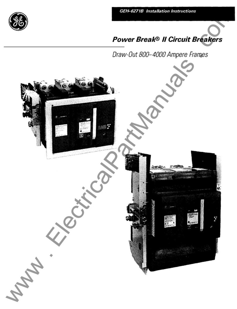
GEH-62798
Power
Break@
II
Circuit Breaker
Accessories
Key
Interlock
Mounting
Provision
Introduction
The
Kev
Interlock
Mountirnr Provision. shown
in
FiQUre
1,
can
1
be
installed
on
800~000
amp.ere
frame
P~wer
Break®
II
circuit
breakers.
A single
lock
body
with
one
to
four
key-lock
cylinders
can
be
installed.
The
GE
catalog
number
is
SPK4.
The
key
lock
must
have a
zero
extension
when
the
bolt
is
withdrawn
with 0.75-inch
extension
when
the
bolt
is
extended.
The
lock
may
be
up
to
1.50
inch
wide.
Catalog
numbers
for
suitable
locks
from
ABB-Kirk®
and
Superior
Interlock
Co.
are
listed in
Table
1.
Figure
1.
The
Key
Interlock
mounted
on
a
circuit
breaker.
# ABB-Kirk® Superior
Approx.
Locks Cat.
No.
Cat.
No.
Lock Length
1
KFNOOOOI
1 S105827Y 2.38"
2 KFN00002 1 S105828Y 3.38"
3
KFN00003_
1
Sl05829Y
4.38"
4 \
KFN00004_
1 I Sl05827-4Y I 5.48"
1
Final
digit
may
be
0,
1,
2,
or
3
depending
on
key
removable
positions.
Table
1.
Catalog
numbers
of
suitable
Key
Interlock
models.
Operation
The
Kev
Interlock
prevents
the
breaker
from
closing-
bv
holding
the
padlo~k
hasp
extended,
thus
keeping'"'
th~
trip
latch
in
the
tripped
position.
A
secondary
padlock
lever
is
included
with
the
Key
Interlock,
since
the
Key
Interlock
blocks
easy access
to
the
standard
padlock
hasp.
To
operate,
use
the
following
procedure:
1.
Trip
the
breaker
(press
the
OFF
button).
2. Grasp
the
ring
to
pull
out
the
nylon-coated
padlock
hasp.
Note
that
if
the
breaker
contacts
are
closed,
the
padlock
hasp
will
not
pull
out.
Do
not
exceed
10
lb
pulling
force
on
the
ring.
3.
Turn
the
key,
securing
the
padlock
hasp
in
the
extended
position,
as
illustrated
in
Figure
2.
The
breaker
cannot
be
closed
until
the
Key
Interlock
is
disengaged.
4.
Rotate
the
secondary
padlock
lever
out
and
attach
padlocks,
if
desired,
as
illustrated
in
Figure
3.
r:A
llTTnN~
RPpP~tPrl
~ttPmpt~
tn
cln~P
~
lnrkPrl-ont
circuit
breaker
will
damage
the
breaker
mechanism.
ATTENTION:
Les
tentatives a
maintes
fermer
un
disjoncteur
verrouille
en
pos1t1on
"ouvert"
endommageront
le
mecanisme
de
disjoncteur.
Figure
2.
View
of
the
breaker,
showing
the
padlock
hasp
held
extended
by
the
Key
interiock.
Courtesy of NationalSwitchgear.com
Figure
3,
The
Key
Interlock
with
a
padlock
attached.
Installation
WARNING:
Before
instaiiing
any accessories,
turn
the
breaker
off,
disconnect
it
from
all voltage sources,
and
discharge
the
closing
springs.
AVERTJSSEMENT:
Avant
d1
instaiier
tout accessoire,
mettre
le
disjoncteur
en
position
OFF, le
rlt.ronnPrtPr
de
toute
tension
d'alimentation,
et
decharger
les
ressorts
d'
armemen
t.
Use
the
following
procedure
to
install
the
Key
Interlock
Mounting
Provision.
Figure
4 is
an
exploded
view
of
the
installation.
1.
If
a
trim
plate
is
installed.
on
the
?reaker,
ioosen
the
wur
screws
secunng
the
tnm-plate
assembly
and
remove
the
trim
plate
from
the
breaker.
2.
Loosen
the
four
screws
at
the
corners
of
the
breaker
cover.
Remove
the
cover
from
the
breaker
face.
3.
Drill
four
15164-inch
(0.234
inch)
holes
ihrough
ihe
cover, as
shown
in
Figure
5.
Figure
5.
The
inside
of
the
breaker
cover,
showing
the
mounting
holes
being
drilled.
4.
Mount
the
lock
mounting
plate
to
the
cover, as
shown
in
Figure
6,
with
four
#8-32
flathead
screws
and
lock
washers.
Figure
6.
The
inside
of
the
breaker
cover,
showing
the
screws
being
attached
to
the
Key
Interlock
mounting
plate.
5.
.A.ttach
the
Key
Interlock
bodv
to
the
mountine:
plate
with two 1
14-20
screws
and
lock
washers,
a~
shown
in
Figure
7.
Courtesy of NationalSwitchgear.com
Figure
7.
The
Key
Interlock
body
attached
to
the
mounting
plate.
6.
For
a single key lock, skip to
Step
7.
For
two,
three,
or
four
key locks,
remove
one,
two,
or
three
knockouts,
respectively. Place
the
cover
face
up
on
a levei
work
surface.
Hoid
a
large
screw
driver
'UPrttr~Jly,
with
thP
ttp
~t
thP
rPntPr
of
thP
l
_4()..inrh
diameter
knockout,
and
strike
the
end
of
the
screw
driver
to
remove
the
knockout.
7.
Mount
the
Key
Interlock
cover with two #8-32
screws
with
integral
lock
washers.
8.
Pull
the
charging
handle
out
once
and
ratchet
it
to
take
the
heavy closing-spring
force
off
the
hanrlle.
Holrl
thP.
hanrlle
ont
nearly
perpendicular
to
the
breaker,
then
fit
it
through
the
handle
slot
in
the
breaker
cover.
9. Ensure that
the
Key Interlock slide
does
not
project across the
5132
x i
2~2
11
siot
in
the cover,
or
:1-
wn.:11
:....,-,.l'lr,,
..
&~
•
.,,..
Y.&~,f-1,.
..
h..o.
....,.
..
,T"'..-..
...-.1'11.~~~,I .-..t':llrlln.l"'I,
h~r"'
.LI,
ff~
ll.Ll,ic;.L.Lic;.L,c;
TI'.LI..L.L
l,ll'<;,
.L.LJ.LVU-'-'U'C&l.'<;,'L&
...
Q.~U''--
.u.u.,.t'
as
the
cover
is
installed.
damal!inl?'
the
Kev
Interlock
slide.
H
necessary;
turn
th;
k;y
to
retra~t
the
lock
bolt
and
slide.
10.
To
prevent
damage
to
the
breaker
cover,
check
11
.L.L•
12.
LI_
_ r _ n
__
..!
_
-·
Ule
IOllUWlUg:
e
Tl...-
-1,
..
-·-,
..
-
----"""-~
..,1--
..
TLI;
.£'I
,,..~
....
+~~~,t
;,.....
.1
uc;
d.1UU111.lU.ll1
d.\...l....C;:!1;:)Vl Y
;:,1c;c;vc;
.I.~
I....C.I.J.LC1
\...U
J.U
its window.
•
The
Trip
Unit
flange
projects
through
its
window.
•
The
gray-painted
wire
channel
is
completely
inside
the
cover.
•
The
cover
is
inboard
of
the
trim
flanges
of
both
terminal
blocks.
Slide
the
cover completely dmvn
on
the
hrP'..'.11.Pr.
Install
the
four
cover
screws
and
torque
them
to
15 in-lb.
Attach
the
split
ring
through
the
lower
%2''-
diameter
hole
in
the
nylon-coated
hasp,
as
shuwn
in
Figure
2.
(Omit
this
step
if
a
Door
Interlock,
Cat. No. SPDIL,
is
installed.)
CAUTION:
Do
not
attempt
to
install
the
breaker
cover
if
the
lock
bolt
is
extended:
as
shown
in
Figure
7.
Turn
the
key so
that
the
lock
boit
retracts
and
disengages
the
interlock
slide,
to
prevent
the
damage
described
in
step
9.
ATTENTION: Il
ne
faut
pas
essayer
d'installer
le
couverde
du
disjoncteur
si
ie
pene
est
tendu,
tel
que
m.ontre ala
Figt1re
7.
Tourner la c!e
de
maniere a
ce
que
le
pene
se
retracte
et
desengage
la
coulisse
de
l'
enclenchement
afin
de
prevenir
le
dommage
decrit
a
l'etape
9.
Courtesy of NationalSwitchgear.com
These instructions
do
not
cover all details or variations in equipment nor do they pro\ide for eveP; possible
contingency
that
may
be
met
in
connection
with
installation,
operation,
or
maintenance.
Should
further
information
be
desired
or
should
particular
problems
arise
that
are
not
covered
sufficiently
for
the
purchaser's
purposes,
the
matter
should
be
referred
to
the
GE Company.
GE Electrical Distribution & Control
General
Electric
Company
41
Woodford
Ave.,
Plainville,
CT
06062
~r:u
a?7DD rv,oa
Courtesy of NationalSwitchgear.com
Other manuals for Power Break II

8

Other GE Circuit Breaker manuals

GE AK-50 Series Technical specifications

GE

GE AK-50 Series Technical specifications

GE GSTG024D User manual

GE

GE GSTG024D User manual

GE AKR User manual

GE

GE AKR User manual

GE AKR-5-100 User manual

GE

GE AKR-5-100 User manual

GE FASHT Series User manual

GE

GE FASHT Series User manual

GE GL 311 F3/4031 P/VE User manual

GE

GE GL 311 F3/4031 P/VE User manual

GE SecoVac Series User manual

GE

GE SecoVac Series User manual

GE Power Break II SPUV012DC User manual

GE

GE Power Break II SPUV012DC User manual

GE SPST480 User manual

GE

GE SPST480 User manual

GE FK800 User manual

GE

GE FK800 User manual

GE WavePro LVPCB User guide

GE

GE WavePro LVPCB User guide

GE Pro-Stock SF250 User manual

GE

GE Pro-Stock SF250 User manual

GE EntelliGuard GBKRKR User manual

GE

GE EntelliGuard GBKRKR User manual

GE AM-13.8-500-5C User manual

GE

GE AM-13.8-500-5C User manual

GE AKR-3-50 User manual

GE

GE AKR-3-50 User manual

GE MicroVersaTripPlus AK-50 User manual

GE

GE MicroVersaTripPlus AK-50 User manual

GE A Series Pro-Stock THQB User manual

GE

GE A Series Pro-Stock THQB User manual

GE AM-4.16-250-6 User manual

GE

GE AM-4.16-250-6 User manual

GE Power-Break TSUV1 User manual

GE

GE Power-Break TSUV1 User manual

GE AKR-30 Series User manual

GE

GE AKR-30 Series User manual

GE EntelliGuard L User manual

GE

GE EntelliGuard L User manual

GE GCCC024DR User manual

GE

GE GCCC024DR User manual

GE Spectra Series User manual

GE

GE Spectra Series User manual

GE M-Pact Plus User manual

GE

GE M-Pact Plus User manual

Popular Circuit Breaker manuals by other brands

Siemens HBLQR quick start guide

Siemens

Siemens HBLQR quick start guide

Moeller Xcomfort CJAU-01 Assembly instructions

Moeller

Moeller Xcomfort CJAU-01 Assembly instructions

CHINT NM1 Series User instruction

CHINT

CHINT NM1 Series User instruction

ABB SACE Tmax XT manual

ABB

ABB SACE Tmax XT manual

TERASAKI TemBreak PRO XDM1 instruction manual

TERASAKI

TERASAKI TemBreak PRO XDM1 instruction manual

FRANKLINWH CSR2100 user manual

FRANKLINWH

FRANKLINWH CSR2100 user manual

Siemens PCBMRC3 manual

Siemens

Siemens PCBMRC3 manual

Siemens 3VA20 JP Series operating instructions

Siemens

Siemens 3VA20 JP Series operating instructions

Eaton IZM20 manual

Eaton

Eaton IZM20 manual

OEZ SE-BD-00 UA01 Series Instructions for use

OEZ

OEZ SE-BD-00 UA01 Series Instructions for use

OEZ LMF Instructions for use

OEZ

OEZ LMF Instructions for use

Siemens 3VF3 operating instructions

Siemens

Siemens 3VF3 operating instructions

Siemens 3WN1 operating instructions

Siemens

Siemens 3WN1 operating instructions

Doepke DRCBO 4 Hi 1 Installation and operating manual

Doepke

Doepke DRCBO 4 Hi 1 Installation and operating manual

Eaton Power Defense PDG4XROP Series Instruction leaflet

Eaton

Eaton Power Defense PDG4XROP Series Instruction leaflet

Siemens SION 3AE operating instructions

Siemens

Siemens SION 3AE operating instructions

WEG DWB400 quick guide

WEG

WEG DWB400 quick guide

Siemens 3VL21 KN30 Series manual

Siemens

Siemens 3VL21 KN30 Series manual

manuals.online logo
manuals.online logoBrands
  • About & Mission
  • Contact us
  • Privacy Policy
  • Terms and Conditions

Copyright 2025 Manuals.Online. All Rights Reserved.