GEM 567 BioStar control User manual

GEMÜ 567 BioStar control
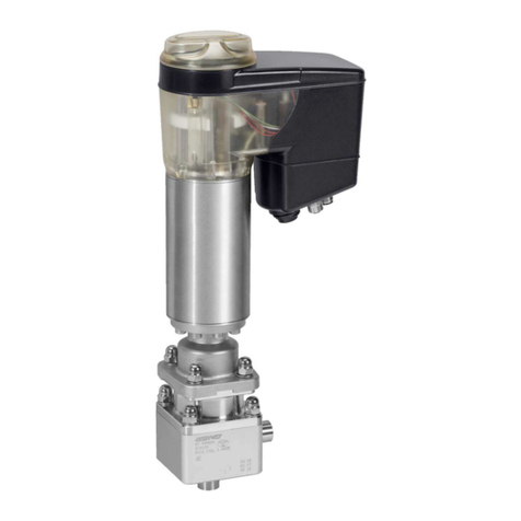
Pneumatically operated control valve
Operating instructions
EN
further information
webcode: GW-567

All rights including copyrights or industrial property rights are expressly reserved.
Keep the document for future reference.
© GEMÜ Gebr. Müller Apparatebau GmbH & Co. KG
16.07.2021
www.gemu-group.com2 / 54GEMÜ 567 BioStar control

Contents
1 General information ............................................. 4
1.1 Information .................................................... 4
1.2 Symbols used ................................................ 4
1.3 Definition of terms ........................................ 4
1.4 Warning notes ............................................... 4
2 Safety information ............................................... 5
3 Product description ............................................. 5
3.7 Product label ................................................. 7
4 Correct use .......................................................... 7
5 Order data ........................................................... 8
6 Technical data ..................................................... 11
6.1 Medium .......................................................... 11
6.2 Temperature .................................................. 11
6.3 Pressure ......................................................... 11
6.4 Product compliance ...................................... 15
6.5 Mechanical data ............................................ 15
7 Dimensions .......................................................... 16
7.1 Actuator dimensions ..................................... 16
7.2 Body dimensions ........................................... 17
8 Manufacturer's information .................................. 37
8.1 Delivery .......................................................... 37
8.2 Packaging ...................................................... 37
8.3 Transport ....................................................... 37
8.4 Storage ........................................................... 37
9 Installation in piping ............................................ 37
9.1 Installation location ....................................... 37
9.2 Preparing for installation .............................. 37
9.3 Installation with clamp connections ............ 38
9.4 Installation with butt weld spigots ............... 38
10 Mounting ............................................................. 39
12 Troubleshooting .................................................. 41
13 Inspection and maintenance ................................ 42
14 Removal from piping ............................................ 51
15 Disposal .............................................................. 51
16 Returns ................................................................ 51
17 Declaration of Incorporation according to
2006/42/EC (Machinery Directive) ....................... 52
18 Declaration of conformity according to 2014/68/
EU (Pressure Equipment Directive) ...................... 53
GEMÜ 567 BioStar controlwww.gemu-group.com 3 / 54

www.gemu-group.com4 / 54GEMÜ 567 BioStar control
1 General information
1.1 Information
•The descriptions and instructions apply to the standard ver-
sions. For special versions not described in this document
the basic information contained herein applies in combina-
tion with any additional special documentation.
•Correct installation, operation, maintenance and repair work
ensure faultless operation of the product.
•Should there be any doubts or misunderstandings, the Ger-
man version is the authoritative document.
•Contact us at the address on the last page for staff training
information.
1.2 Symbols used
The following symbols are used in this document:
Symbol Meaning
Tasks to be performed
Response(s) to tasks
– Lists
1.3 Definition of terms
Working medium
The medium that flows through the GEMÜ product.
PD
PD = Plug Diaphragm
1.4 Warning notes
Wherever possible, warning notes are organised according to
the following scheme:
SIGNAL WORD
Type and source of the danger
Possible
symbol for the
specific
danger
Possible consequences of non-observance.
Measures for avoiding danger.
Warning notes are always marked with a signal word and
sometimes also with a symbol for the specific danger.
The following signal words and danger levels are used:
DANGER
Imminent danger!
▶Non-observance can cause death or
severe injury.
WARNING
Potentially dangerous situation!
▶Non-observance can cause death or
severe injury.
CAUTION
Potentially dangerous situation!
▶Non-observance can cause moderate
to light injury.
NOTICE
Potentially dangerous situation!
▶Non-observance can cause damage to
property.
The following symbols for the specific dangers can be used
within a warning note:
Symbol Meaning
Danger of explosion
Corrosive chemicals!
Hot plant components!

www.gemu-group.com 5 / 54 GEMÜ 567 BioStar control
2 Safety information
The safety information in this document refers only to an indi-
vidual product. Potentially dangerous conditions can arise in
combination with other plant components, which need to be
considered on the basis of a risk analysis. The operator is re-
sponsible for the production of the risk analysis and for com-
pliance with the resulting precautionary measures and re-
gional safety regulations.
The document contains fundamental safety information that
must be observed during commissioning, operation and main-
tenance. Non-compliance with these instructions may cause:
•Personal hazard due to electrical, mechanical and chemical
effects.
•Hazard to nearby equipment.
•Failure of important functions.
•Hazard to the environment due to the leakage of dangerous
materials.
The safety information does not take into account:
•Unexpected incidents and events, which may occur during
installation, operation and maintenance.
•Local safety regulations which must be adhered to by the
operator and by any additional installation personnel.
Prior to commissioning:
1. Transport and store the product correctly.
2. Do not paint the bolts and plastic parts of the product.
3. Carry out installation and commissioning using trained
personnel.
4. Provide adequate training for installation and operating
personnel.
5. Ensure that the contents of the document have been fully
understood by the responsible personnel.
6. Define the areas of responsibility.
7. Observe the safety data sheets.
8. Observe the safety regulations for the media used.
During operation:
9. Keep this document available at the place of use.
10. Observe the safety information.
11. Operate the product in accordance with this document.
12. Operate the product in accordance with the specifications.
13. Maintain the product correctly.
14. Do not carry out any maintenance work and repairs not de-
scribed in this document without consulting the manufac-
turer first.
In cases of uncertainty:
15. Consult the nearest GEMÜ sales office.
3 Product description
3.1 Construction
1
3
2
4
5
5
Item Name Materials
1 Pneumatic actuator connection
2 Actuator housing 1.4305
3 Distance piece 1.4404
4 Valve body with leak detection hole 1.4435
5 CONEXO RFID chip
3.2 Description
The GEMÜ 567 BioStar Control 2/2-way diaphragm globe
valve is designed for use in sterile applications. Flow rates
range from 80 l/h to 63 m³/h, depending on the version. The
sealing concept of the valve is based on the GEMÜ PD design.
All actuator parts (except the seals) are made from stainless
steel. Normally Closed, Normally Open and Double Acting
control functions are available.
3.3 Function
The product is a pneumatic 2/2-way diaphragm globe valve
made of stainless steel. The GEMÜ 567 2/2-way diaphragm
globe valve is designed for installation in piping systems and
has been equipped with a GEMÜ PD design. Flow rates of
between 80 l/h and 63 m³/h are possible, depending on the
version.
3 Product description

3.4 PD seal system without bypass
1
3
4
2
5
Seal material code 4 Seal material code 5
Item Name Materials
1 Plug diaphragm PTFE
2 Support ring 1.4435 (316L)
3 O-ring FKM
4 Regulating cone 1.4435 (316L)
5 PTFE plug diaphragm with regulating cone
3.5 PD seal system with bypass
1
2
3
4
5
only for actuator size 2
Item Name Materials
1 Plug diaphragm FKM, PTFE PTFE
2 Support ring 1.4435 (316L)
3 O-ring FKM
4 Regulating cone 1.4435 (316L)
5 Bypass valve diaphragm
www.gemu-group.com6 / 54GEMÜ 567 BioStar control
3 Product description

www.gemu-group.com 7 / 54 GEMÜ 567 BioStar control
3.6 Installation position for optimized draining
in open and closed position in open position
3.7 Product label
The product label is located on the actuator. Product label
data (example):
Design in accordance with order data
Item number
Device-specific data
Year of manufacture
Traceability number Counting number
12103529 I0001
The month of manufacture is encoded in the traceability num-
ber and can be obtained from GEMÜ. The product was manu-
factured in Germany.
4 Correct use
DANGER
Danger of explosion
▶Risk of death or severe injury.
●Do not use the product in potentially
explosive zones.
WARNING
Improper use of the product
▶Risk of severe injury or death.
▶Manufacturer liability and guarantee will be void.
●Only use the product in accordance with the operating
conditions specified in the contract documentation and in
this document.
The product is designed for installation in piping systems and
for controlling a working medium.
The product is not intended for use in potentially explosive
areas.
●Use the product in accordance with the technical data.
4 Correct use

5 Order data
The order data provide an overview of standard configurations.
Please check the availability before ordering. Other configurations available on request.
Order codes
1 Type Code
Control valve 567
2 DN Code
DN 8 8
DN 10 10
DN 15 15
DN 20 20
DN 25 25
DN 32 32
DN 40 40
DN 50 50
DN 65 65
3 Body configuration Code
2-way angle body E
2-way angle body with bypass M
4 Connection type Code
Spigot
Spigot DIN 0
Spigot EN 10357 series A (formerly DIN 11850
series 2)/DIN 11866 series A
17
Spigot ASME BPE / DIN 11866 series C 59
Spigot ISO 1127/EN 10357 series C/DIN 11866
series B
60
Clamp
Clamp DIN 32676 series B 82
Clamp DIN 32676 series A 86
Clamp ASME BPE 88
5 Valve body material Code
1.4435 (316L), block material 41
1.4435 (BN2), block material, Δ Fe < 0.5% 43
6 Seal material Code
Actuator seal PTFE / seat seal FKM 4
Actuator seal PTFE / seat seal PTFE 5
Actuator seal PTFE / seat seal FKM / bypass seal
EPDM
bypass diaphragm code 13
43
Actuator seal PTFE / seat seal FKM / bypass seal
PTFE
bypass diaphragm code 54
45
Actuator seal PTFE / seat seal FKM / bypass seal
EPDM
bypass diaphragm code 17
47
6 Continuation of Seal material Code
Actuator seal PTFE / seat seal PTFE / bypass seal
PTFE
bypass diaphragm code 54
55
Actuator seal PTFE / seat seal FFKM F
Actuator seal PTFE / seat seal FFKM / bypass seal
PTFE
bypass diaphragm code 54
F5
7 Control function Code
Normally closed (NC) 1
Normally open (NO) 2
Double acting (DA) 3
8 Actuator version Code
Actuator size 2,
pneumatically operated
2T1
Actuator size 3,
pneumatically operated
3T1
Actuator size 4,
pneumatically operated
4T1
Actuator size 5T1 5T1
9 Control characteristic Code
Modified equal-percentage G
Linear L
10 Kv value Code
80l/h AA
100 l/h AB
160 l/h BC
250 l/h BD
400 l/h BE
630 l/h CF
1.0 m³/h CG
1.6 m³/h DH
2.6 m³/h EJ
4.1 m³/h G1
8.0 m³/h H2
12.5 m³/h J3
14.0 m³/h K4
18.0 m³/h K5
25.0 m³/h K6
32.0 m³/h M7
40.0 m³/h M8
50.0 m³/h N9
63.0 m³/h NK
5 Order data
www.gemu-group.com8 / 54GEMÜ 567 BioStar control

11 Bypass actuator version Code
Pneumatically operated, normally closed, dia-
phragm size 8,
11
Pneumatically operated, normally open, diaphragm
size 8,
12
Manually operated, with seal adjuster, diaphragm
size 8,
S0
12 Special specification Code
Ra ≤ 0.25 µm (10 µin.) for media wetted surfaces
*),
in accordance with DIN 11866 HE5,
electropolished internal/external,
*) for inner pipe diameters < 6 mm, in the spigot Ra
≤ 0.38 µm
1516
Ra ≤ 0.25 µm (10 µin.) for media wetted surfaces
*),
in accordance with DIN 11866 H5,
mechanically polished internal,
*) for inner pipe diameters < 6 mm, in the spigot Ra
≤ 0.38 µm
1527
Ra ≤ 0.4 µm (15 µin.) for media wetted surfaces,
in accordance with DIN 11866 H4,
mechanically polished internal
1536
Ra ≤ 0.4 µm (15 µin.) for media wetted surfaces,
in accordance with DIN 11866 HE4,
electropolished internal/external
1537
Ra max. 0.51 µm (20 µin.) for media wetted sur-
faces,
in accordance with ASME BPE SF1,
mechanically polished internal
SF1
Ra max. 0.38 µm (15 µin.) for media wetted sur-
faces,
in accordance with ASME BPE SF4,
electropolished internal/external
SF4
Ra max. 0.51 µm (20 µin.) for media wetted sur-
faces,
in accordance with ASME BPE SF5,
electropolished internal/external
SF5
13 Special version Code
Special version for 3A M
14 CONEXO Code
Without
Integrated RFID chip for electronic identification
and traceability
C
5 Order data
www.gemu-group.com 9 / 54 GEMÜ 567 BioStar control

Order example without bypass
Ordering option Code Description
1 Type 567 Control valve
2 DN 15 DN 15
3 Body configuration E 2-way angle body
4 Connection type 17 Spigot EN 10357 series A (formerly DIN 11850 series 2)/DIN 11866
series A
5 Valve body material 41 1.4435 (316L), block material
6 Seal material 5 Actuator seal PTFE / seat seal PTFE
7 Control function 1 Normally closed (NC)
8 Actuator version 2T1 Actuator size 2,
pneumatically operated
9 Control characteristic G Modified equal-percentage
10 Kv value G1 4.1 m³/h
11 Special specification 1536 Ra ≤ 0.4 µm (15 µin.) for media wetted surfaces,
in accordance with DIN 11866 H4,
mechanically polished internal
12 Special version M Special version for 3A
13 CONEXO C Integrated RFID chip for electronic identification and traceability
Order example with bypass
Ordering option Code Description
1 Type 567 Control valve
2 DN 15 DN 15
3 Body configuration M 2-way angle body with bypass
4 Connection type 17 Spigot EN 10357 series A (formerly DIN 11850 series 2)/DIN 11866
series A
5 Valve body material 41 1.4435 (316L), block material
6 Seal material 55 Actuator seal PTFE / seat seal PTFE / bypass seal PTFE
bypass diaphragm code 54
7 Control function 1 Normally closed (NC)
8 Actuator version 2T1 Actuator size 2,
pneumatically operated
9 Control characteristic G Modified equal-percentage
10 Kv value G1 4.1 m³/h
11 Bypass actuator version S0 Manually operated, with seal adjuster, diaphragm size 8,
12 Special specification 1536 Ra ≤ 0.4 µm (15 µin.) for media wetted surfaces,
in accordance with DIN 11866 H4,
mechanically polished internal
13 Special version M Special version for 3A
14 CONEXO C Integrated RFID chip for electronic identification and traceability
5 Order data
www.gemu-group.com10 / 54GEMÜ 567 BioStar control

6 Technical data
6.1 Medium
Working medium: Corrosive, inert, gaseous and liquid media which have no negative impact on the physical and
chemical properties of the body and diaphragm material.
6.2 Temperature
Media temperature: Without bypass -10 — 160 °C
With bypass -10 — 100 °C
Observe pressure/temperature diagram
Sterilization temperature: Seat seal FKM without bypass, (code 4) 160 °C 1), steam max. 30 min 2)
Seat seal PTFE without bypass, (code 5) 160 °C 1), steam max. 30 min 2)
Seat seal FKM
bypass diaphragm material EPDM,
(code 43)
150 °C 3), max. 30 min
Seat seal FKM
bypass diaphragm material PTFE/EPDM,
PTFE laminated, (code 45)
150 °C 3), max. 30 min
Seat seal FKM
bypass diaphragm material EPDM,
(code 47)
150 °C 3), max. 30 min
Seat seal PTFE
bypass diaphragm material PTFE/EPDM,
PTFE laminated, (code 55)
150 °C 3), max. 30 min
1) The sterilization temperature is only valid for steam (saturated steam) or superheated water.
2) Longer sterilization times or continuous operation on request.
3) If the sterilization temperatures listed above are applied to the EPDM diaphragms for longer periods of time,
the service life of the diaphragms will be reduced. In these cases, maintenance cycles must be adapted ac-
cordingly. This also applies to PTFE diaphragms exposed to high temperature fluctuations. The mainten-
ance cycles must be adapted accordingly.
Ambient temperature: -10 — 60 °C
Storage temperature: 0 — 40 °C
6.3 Pressure
Operating pressure: 0 — 10 bar
Pressure/Temperature diagram
11
10
9
8
7
6
5
4
3
2
1
-20 -10 0 20 40 60 80 100 120 140 160130
Temperature [°C]
Operating pressure [bar]
GEMÜ 567 BioStar controlwww.gemu-group.com 11 / 54
6 Technical data

Control pressure: DN Actuator size Control function Control pressure
8, 10, 15, 20 2 Control pressure
with main valve ac-
tuator
1 5.0 to 7 bar
2 + 3 max. 4.5 bar
Control pressure
with bypass actu-
ator
1 3.5 to 7 bar
2 + 3 max. 4.5 bar
20, 25 3 Without bypass 1 4.5 to 7 bar
2 +3 max. 5.5 bar
32, 40, 50, 65 4, 5 Without bypass 1 4.5 to 7 bar
2 +3 max. 5.5 bar
Control pressure diagram c.f. 2 + 3
0,0
0,5
1,0
1,5
2,0
2,5
3,0
3,5
4,0
4,5
010
5,0
24 6 8
Control pressure
Operating pressure
Main actuator
Bypass actuator
with PTFE diaphragm
Bypass actuator
with elastomer diaphragm
Leakage rate: Control valve
Seat seal Standard Test procedure Leakage rate Test medium
FKM, PTFE DIN EN 60534-4 1 VI Air
www.gemu-group.com12 / 54GEMÜ 567 BioStar control
6 Technical data

Kv values:
100
80
60
40
20
100
80604020
0
L
G
0
Kv value [%]
Stroke [%]
Code 17, 60, 82 and 86
AG Seal ma-
terial
code
Control
character-
istic
Kv value DN 8 DN
10
DN
15
DN
20
DN
25
DN
32
DN
40
DN
50
2, 3 4, 43, 45,
47, F, F5
GAA, LAA 80l/h X X X - - - - -
GAB, LAB 100 l/h X X X - - - - -
GBC, LBC 160 l/h X X X - - - - -
GBD, LBD 250 l/h X X X - - - - -
GBE, LBE 400 l/h X X X - - - - -
GCF, LCF 630 l/h X X X - - - - -
GCG, LCG 1.0 m³/h - X X - - - - -
5, 55 GDH, LDH 1.6 m³/h - X X - - - - -
GEJ, LEJ 2.6 m³/h - - X - - - - -
GG1, LG1 4.1 m³/h - - X - - - - -
5 GH2, LH2 8.0 m³/h - - - X X - - -
GJ3, LJ3 12.5 m³/h - - - - X - - -
4 5 GK4, LK4 14.0 m³/h - - - - - X X -
GK5, LK5 18.0 m³/h - - - - - X X -
GK6, LK6 25.0 m³/h - - - - - X X -
GM7, LM7 32.0 m³/h - - - - - - X -
GM8, LM8 40.0 m³/h - - - - - - X -
5 5 GN9, LN9 50.0 m³/h - - - - - - - X
GNK, LNK 63.0 m³/h - - - - - - - X
GEMÜ 567 BioStar controlwww.gemu-group.com 13 / 54
6 Technical data

Kv values: Code 59 and 88
AG Seal mater-
ial code
Control
character-
istic
Kv value DN 15 DN 20 DN 25 DN 40 DN 50 DN 65
2, 3 4, 43,
45, 47,
F, F5
GAA, LAA 80l/h X X - - - -
GAB, LAB 100 l/h X X - - - -
GBC, LBC 160 l/h X X - - - -
GBD, LBD 250 l/h X X - - - -
GBE, LBE 400 l/h X X - - - -
GCF, LCF 630 l/h X X - - - -
GCG, LCG 1.0 m³/h X X - - - -
5, 55 GDH, LDH 1.6 m³/h X X - - - -
GEJ, LEJ 2.6 m³/h - X - - - -
GG1, LG1 4.1 m³/h - X - - - -
5 GH2, LH2 8.0 m³/h - - X - - -
4 5 GK4, LK4 14.0 m³/h - - - X X -
GK5, LK5 18.0 m³/h - - - X X -
GK6, LK6 25.0 m³/h - - - X X -
GM7, LM7 32.0 m³/h - - - - X -
GM8, LM8 40.0 m³/h - - - - X -
5 5 GN9, LN9 50.0 m³/h - - - - - X
GNK, LNK 63.0 m³/h - - - - - X
AG = actuator size
Kv values of bypass 2.1 m³/h
Kv values determined acc.to DIN EN 60534.
www.gemu-group.com14 / 54GEMÜ 567 BioStar control
6 Technical data

6.4 Product compliance
Machinery Directive: 2006/42/EC
EMC Directive: 2014/30/EU
Food: FDA
USP Class VI
Regulation (EC) No. 1935/2004
Regulation (EC) No. 10/2011
6.5 Mechanical data
Weight: Actuator
Actuator size 2 2.7 kg
Actuator size 3 5.1 kg
Actuator size 4 10.3 kg
Actuator size 5 20.4 kg
Valve body
Actuator size 2 1.6 kg
Actuator size 3 2.8 kg
Actuator size 4 4.3 kg
Actuator size 5 7.6 kg
GEMÜ 567 BioStar controlwww.gemu-group.com 15 / 54
6 Technical data

7 Dimensions
7.1 Actuator dimensions
CT *
A
ØB
M
A1
G G
A2
DN Actuator
size
A A1 A2 G ØB M
8, 10, 15,
20
2 170.0 69.2 53.0 G1/4 90.0 M16x1
20, 25 3 199.0 97.0 56.5 G1/4 114.0 M16x1
32, 40, 50,
65
4 250.4 100.0 70.5 G1/4 144.0 M16x1
5 317.8 147.5 - G1/4 240.0 M26x1.5
Dimensions in mm
* CT = A + H1 (see body dimensions)
www.gemu-group.com16 / 54GEMÜ 567 BioStar control
7 Dimensions

7.2 Body dimensions
7.2.1 Spigot without bypass code 0
H2
E
L
c
c
s
d
s
d
LE
H1
CZ
Z
AG DN Connection type code 0 1)
Material code 41 2), 43 2)
Seat
size
(code)
L□E c Øz LE H1 H2 cz Ød s
2, 3 15 A 45.0 75.0 20.0 2.0 44.0 21.0 40.5 6.5 18.0 1.5
B45.0 75.0 20.0 4.0 44.0 21.0 39.5 5.5 18.0 1.5
C45.0 75.0 20.0 6.0 44.0 21.0 38.5 4.5 18.0 1.5
D45.0 75.0 20.0 8.0 44.0 21.0 41.0 3.5 18.0 1.5
E45.0 75.0 20.0 10.0 44.0 21.0 40.0 2.5 18.0 1.5
G45.0 75.0 20.0 15.0 44.0 21.0 37.5 - 18.0 1.5
20 H 55.0 95.0 25.0 20.0 - - - - - -
25 H 55.0 95.0 25.0 20.0 54.0 26.0 50.0 2.5 28.0 1.5
J55.0 95.0 25.0 25.0 54.0 26.0 47.5 0.0 28.0 1.5
Dimensions in mm
AG = actuator size
1) Connection type
Code 0: Spigot DIN
2) Valve body material
Code 41: 1.4435 (316L), block material
Code 43: 1.4435 (BN2), block material, Δ Fe < 0.5%
GEMÜ 567 BioStar controlwww.gemu-group.com 17 / 54
7 Dimensions

7.2.2 Spigot without bypass code 17
H2
E
L
c
c
s
d
s
d
LE
H1
CZ
Z
AG DN Connection type code 17 1)
Material code 41 2), 43 2)
Seat
size
(code)
L□E c Øz LE H1 H2 cz Ød s
2, 3 8 A 45.0 75.0 20.0 2.0 47.5 17.5 40.5 3.0 10.0 1.0
B45.0 75.0 20.0 4.0 47.5 17.5 39.5 2.0 10.0 1.0
C45.0 75.0 20.0 6.0 47.5 17.5 38.5 1.0 10.0 1.0
10 A 45.0 75.0 20.0 2.0 46.5 18.5 41.5 4.0 13.0 1.5
B45.0 75.0 20.0 4.0 46.5 18.5 40.5 3.0 13.0 1.5
C45.0 75.0 20.0 6.0 46.5 18.5 39.5 2.0 13.0 1.5
D45.0 75.0 20.0 8.0 46.5 18.5 38.5 1.0 13.0 1.5
15 A 45.0 75.0 20.0 2.0 43.5 21.5 44.5 7.0 19.0 1.5
B45.0 75.0 20.0 4.0 43.5 21.5 43.5 6.0 19.0 1.5
C45.0 75.0 20.0 6.0 43.5 21.5 42.5 5.0 19.0 1.5
D45.0 75.0 20.0 8.0 43.5 21.5 41.5 4.0 19.0 1.5
E45.0 75.0 20.0 10.0 43.5 21.5 40.5 3.0 19.0 1.5
G45.0 75.0 20.0 15.0 43.5 21.5 38.0 0.5 19.0 1.5
20 H 55.0 95.0 25.0 20.0 56.5 23.5 47.5 0.0 23.0 1.5
25 H 55.0 95.0 25.0 20.0 53.5 26.5 50.5 3.0 29.0 1.5
J55.0 95.0 25.0 25.0 53.5 26.5 48.0 0.5 29.0 1.5
Dimensions in mm
AG = actuator size
1) Connection type
Code 17: Spigot EN 10357 series A (formerly DIN 11850 series 2)/DIN 11866 series A
2) Valve body material
Code 41: 1.4435 (316L), block material
Code 43: 1.4435 (BN2), block material, Δ Fe < 0.5%
www.gemu-group.com18 / 54GEMÜ 567 BioStar control
7 Dimensions

7.2.3 Spigot without bypass code 17
H2
E
L
c
c
s
d
s
d
LE
H1
CZ
Z
AG DN Connection type code 17 1)
Material code 41 2), 43 2)
Seat
size
(code)
L□E c Øz LE H1 H2 cz Ød s
4, 5 32 K 73.0 112.0 20.0 32.0 62.0 31.0 54.5 1.5 38.0 1.5
40 K 73.0 112.0 20.0 32.0 60.4 32.6 53.0 3.0 41.0 1.5
L73.0 112.0 20.0 38.0 60.4 32.6 56.0 0.0 41.0 1.5
50 M 84.0 140.0 20.0 50.0 65.4 38.6 90.0 0.0 53.0 1.5
Dimensions in mm
AG = actuator size
1) Connection type
Code 17: Spigot EN 10357 series A (formerly DIN 11850 series 2)/DIN 11866 series A
2) Valve body material
Code 41: 1.4435 (316L), block material
Code 43: 1.4435 (BN2), block material, Δ Fe < 0.5%
GEMÜ 567 BioStar controlwww.gemu-group.com 19 / 54
7 Dimensions

7.2.4 Spigot without bypass code 59
H2
E
L
c
c
s
d
s
d
LE
H1
CZ
Z
AG DN Connection type code 59 1)
Material code 41 2), 43 2)
Seat
size
(code)
L□E c Øz LE H1 H2 cz Ød s
2, 3 15 A 45.0 75.0 20.0 2.0 46.8 18.2 41.20 3.70 12.70 1.65
B45.0 75.0 20.0 4.0 46.8 18.2 40.20 2.70 12.70 1.65
C45.0 75.0 20.0 6.0 46.8 18.2 39.20 1.70 12.70 1.65
D45.0 75.0 20.0 8.0 46.8 18.2 38.20 0.70 12.70 1.65
20 A 45.0 75.0 20.0 2.0 48.6 21.4 44.38 6.88 19.05 1.65
B45.0 75.0 20.0 4.0 43.6 21.4 43.38 5.88 19.05 1.65
C45.0 75.0 20.0 6.0 43.6 21.4 42.38 4.88 19.05 1.65
D45.0 75.0 20.0 8.0 43.6 21.4 41.38 3.88 19.05 1.65
E45.0 75.0 20.0 10.0 43.6 21.4 40.38 2.88 19.05 1.65
G45.0 75.0 20.0 15.0 43.6 21.4 37.88 0.38 19.05 1.65
25 H 55.0 95.0 25.0 20.0 55.4 24.6 48.60 1.10 25.40 1.70
Dimensions in mm
AG = actuator size
1) Connection type
Code 59: Spigot ASME BPE / DIN 11866 series C
2) Valve body material
Code 41: 1.4435 (316L), block material
Code 43: 1.4435 (BN2), block material, Δ Fe < 0.5%
www.gemu-group.com20 / 54GEMÜ 567 BioStar control
7 Dimensions
Other manuals for 567 BioStar control
1
Table of contents
Other GEM Control Unit manuals