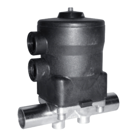
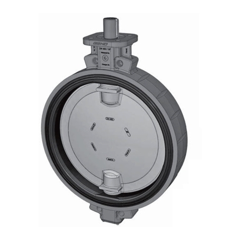
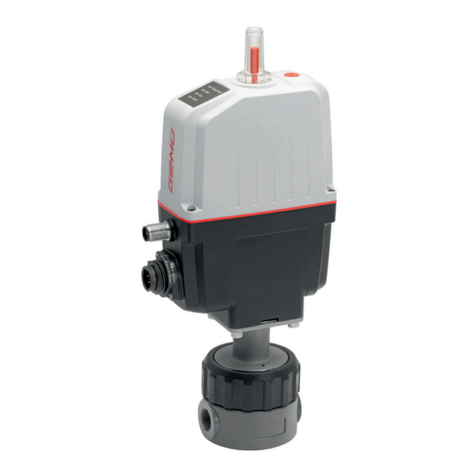
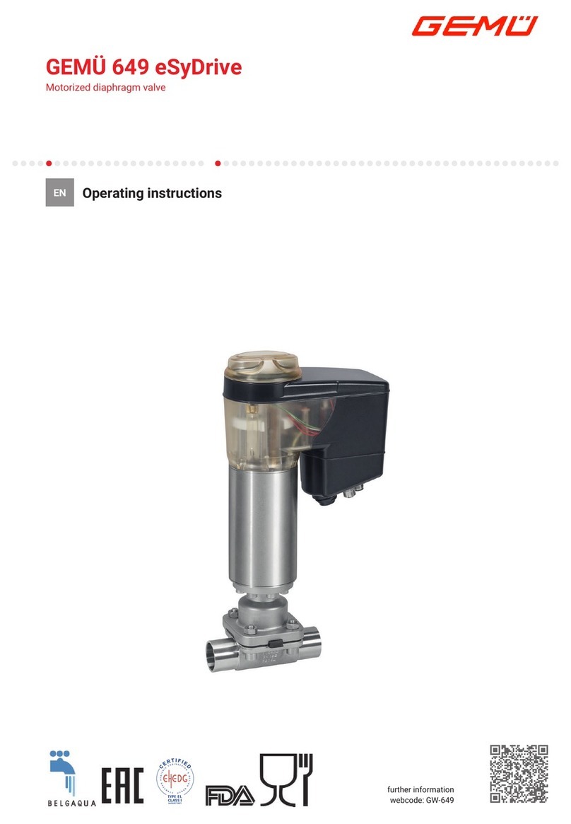
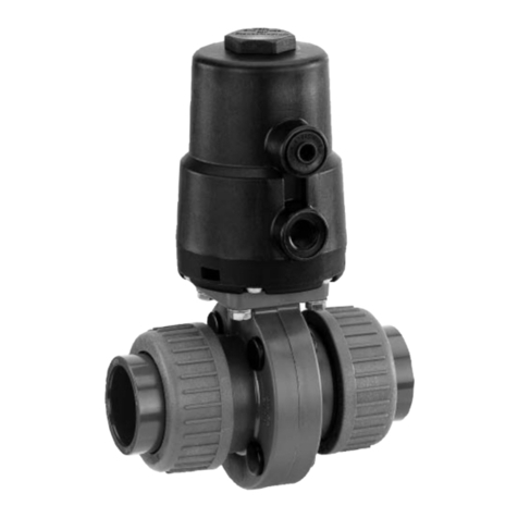
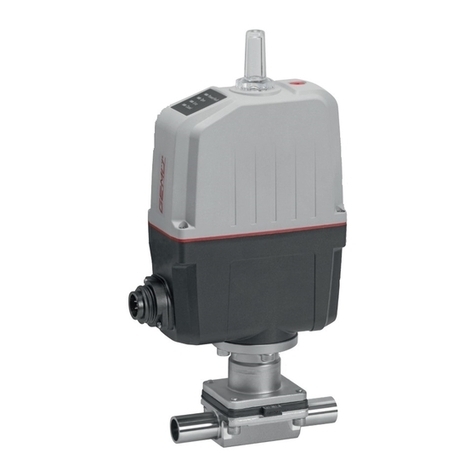
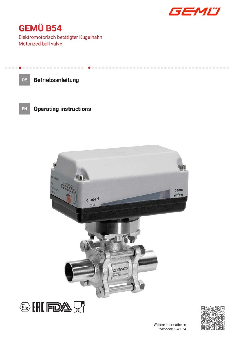
GEM B54 User manual

GEMÜ B54
Motorized ball valve
Operating instructions
EN
further information
webcode: GW-B54

All rights including copyrights or industrial property rights are expressly reserved.
Keep the document for future reference.
© GEMÜ Gebr. Müller Apparatebau GmbH & Co. KG
27.11.2020
www.gemu-group.com2 / 43GEMÜ B54

Contents
1 General information .................................................. 4
1.1 Information .......................................................... 4
1.2 Symbols used ...................................................... 4
1.3 Definition of terms .............................................. 4
1.4 Warning notes ..................................................... 4
2 Safety information .................................................... 5
3 Product description ................................................... 5
3.1 Construction ........................................................ 5
3.2 Description ........................................................... 5
3.3 Function ............................................................... 5
4 GEMÜ CONEXO ......................................................... 5
5 Correct use ............................................................... 6
6 Order data ................................................................. 7
6.1 Ball valve with GEMÜ 9428, 9468 actuator ........ 7
6.2 Ball valve with J+J actuator ............................... 9
6.3 Ball valve with Bernard actuator ......................... 11
7 Ball valve technical data ............................................ 13
7.1 Medium ................................................................ 13
7.2 Temperature ........................................................ 13
7.3 Pressure ............................................................... 13
7.4 Product conformities .......................................... 14
7.5 Mechanical data .................................................. 14
8 Technical data of actuator ......................................... 15
8.1 GEMÜ 9428, 9468 actuators ............................... 15
8.2 Bernard, J+J actuators ....................................... 17
9 Dimensions ............................................................... 18
10 Manufacturer's information ....................................... 25
10.1 Delivery ................................................................ 25
10.2 Packaging ............................................................ 25
10.3 Transport ............................................................. 25
10.4 Storage ................................................................. 25
11 Installation in piping .................................................. 25
11.1 Preparing for installation .................................... 25
11.2 Installation with butt weld spigots ..................... 26
11.3 Installation with clamp connections .................. 27
12 Electrical connection ................................................. 28
12.1 Connection and wiring diagram – actuator ver-
sion 1015, 2015, 3035, 3055 .............................. 28
12.2 Connection and wiring diagram – actuator ver-
sion 2070, 4100, 4200 ......................................... 29
13 Limit switches ........................................................... 30
13.1 Setting the limit switch for 1015, 2015 and
3035 ..................................................................... 30
13.2 Setting the limit switch for 2070, 4100, 4200 .... 31
14 Commissioning ......................................................... 31
15 Operation .................................................................. 32
15.1 Optical position indicator .................................... 32
15.2 Manual override ................................................... 32
15.3 Setting the limit switches ................................... 33
16 Troubleshooting ........................................................ 35
17 Inspection/maintenance ............................................ 36
17.1 Spare parts .......................................................... 37
17.2 Replacing the actuator ........................................ 38
18 Removal from piping ................................................. 40
19 Disposal .................................................................... 40
20 Returns ..................................................................... 40
21 Declaration of Incorporation according to 2006/42/
EC (Machinery Directive) ........................................... 41
22 Declaration of conformity according to 2014/30/EU
(EMC Directive) ......................................................... 42
GEMÜ B54www.gemu-group.com 3 / 43
www.gemu-group.com4 / 43GEMÜ B54
1 General information
1.1 Information
•The descriptions and instructions apply to the standard ver-
sions. For special versions not described in this document
the basic information contained herein applies in combina-
tion with any additional special documentation.
•Correct installation, operation, maintenance and repair work
ensure faultless operation of the product.
•Should there be any doubts or misunderstandings, the Ger-
man version is the authoritative document.
•Contact us at the address on the last page for staff training
information.
1.2 Symbols used
The following symbols are used in this document:
Symbol Meaning
Tasks to be performed
Response(s) to tasks
– Lists
1.3 Definition of terms
Working medium
The medium that flows through the GEMÜ product.
Control medium
The medium whose increasing or decreasing pressure causes
the GEMÜ product to be actuated and operated.
Control function
The possible actuation functions of the GEMÜ product.
1.4 Warning notes
Wherever possible, warning notes are organised according to
the following scheme:
SIGNAL WORD
Type and source of the danger
Possible
symbol for the
specific
danger
Possible consequences of non-observance.
Measures for avoiding danger.
Warning notes are always marked with a signal word and
sometimes also with a symbol for the specific danger.
The following signal words and danger levels are used:
DANGER
Imminent danger!
▶Non-observance can cause death or
severe injury.
WARNING
Potentially dangerous situation!
▶Non-observance can cause death or
severe injury.
CAUTION
Potentially dangerous situation!
▶Non-observance can cause moderate
to light injury.
NOTICE
Potentially dangerous situation!
▶Non-observance can cause damage to
property.
The following symbols for the specific dangers can be used
within a warning note:
Symbol Meaning
Danger of explosion!
Corrosive chemicals!
Hot plant components!
Risk of electric shock
Electric shock by dangerous voltage!

www.gemu-group.com 5 / 43 GEMÜ B54
2 Safety information
The safety information in this document refers only to an indi-
vidual product. Potentially dangerous conditions can arise in
combination with other plant components, which need to be
considered on the basis of a risk analysis. The operator is re-
sponsible for the production of the risk analysis and for com-
pliance with the resulting precautionary measures and re-
gional safety regulations.
The document contains fundamental safety information that
must be observed during commissioning, operation and main-
tenance. Non-compliance with these instructions may cause:
•Personal hazard due to electrical, mechanical and chemical
effects.
•Hazard to nearby equipment.
•Failure of important functions.
•Hazard to the environment due to the leakage of dangerous
materials.
The safety information does not take into account:
•Unexpected incidents and events, which may occur during
installation, operation and maintenance.
•Local safety regulations which must be adhered to by the
operator and by any additional installation personnel.
Prior to commissioning:
1. Transport and store the product correctly.
2. Do not paint the bolts and plastic parts of the product.
3. Carry out installation and commissioning using trained
personnel.
4. Provide adequate training for installation and operating
personnel.
5. Ensure that the contents of the document have been fully
understood by the responsible personnel.
6. Define the areas of responsibility.
7. Observe the safety data sheets.
8. Observe the safety regulations for the media used.
During operation:
9. Keep this document available at the place of use.
10. Observe the safety information.
11. Operate the product in accordance with this document.
12. Operate the product in accordance with the specifications.
13. Maintain the product correctly.
14. Do not carry out any maintenance work and repairs not de-
scribed in this document without consulting the manufac-
turer first.
In cases of uncertainty:
15. Consult the nearest GEMÜ sales office.
3 Product description
3.1 Construction
1
2
3a
4
2
3b
6
C
Item Name Materials
1 Ball valve body ASTM A351/1.4435
(316L)
2 Pipe connections ASTM A351/1.4435
(316L)
3a Actuator housing cover
Actuator version 1006,1015
Actuator version 3035, 3055
Actuator version 4100, 4200
PPO (10% glass fibre
reinforced)
PP (30% glass fibre re-
inforced)
Aluminium
3b Actuator housing base
Actuator version 1006, 1015,
3035, 3055
Actuator version 4100, 4200
PP (30% glass fibre re-
inforced)
Aluminium
4 Optical position indicator PP-R natural
6 Bolt A2 70
Seals TFM
C CONEXO RFID chip
3.2 Description
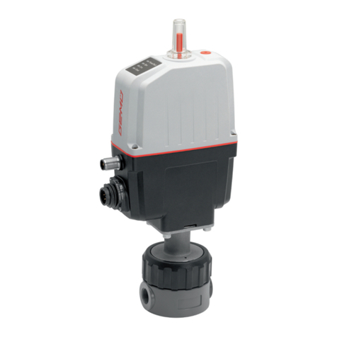
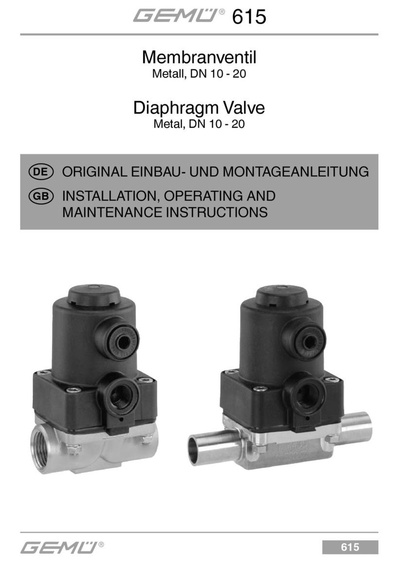
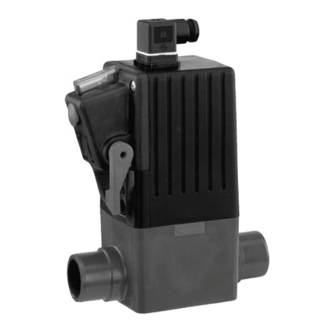
The GEMÜ B54 3-piece 2/2-way metal ball valve is motorized.
It has a plastic actuator housing and is particularly suitable
for requirements in the pharmaceutical, food processing and
biotechnology industries, such as water treatment or sterile
steam generation. Only those plastics which are compliant
with FDA, USP Class VI and EC10/2011 are used for the seals.
3.3 Function
The product is equipped with a top flange in stainless steel. It
has an electric actuator with a powerful DC motor. The reduc-
tion gear in the motor, consisting of a threaded spindle with a
lever, provides the rotation through 90°. The actuator has an
optical position indicator and a manual override as standard.
4 GEMÜ CONEXO
The interaction of valve components that are equipped with
RFID chips and an associated IT infrastructure actively in-
crease process reliability.
4 GEMÜ CONEXO

www.gemu-group.com6 / 43GEMÜ B54
5 Correct use
Thanks to serialization, every valve and every relevant valve
component such as the body, actuator or diaphragm, and
even automation components, can be clearly traced and read
using the CONEXO pen RFID reader. The CONEXO app, which
can be installed on mobile devices, not only facilitates and im-
proves the "installation qualification" process, but also makes
the maintenance process much more transparent and easier
to document. The app actively guides the maintenance techni-
cian through the maintenance schedule and directly provides
him with all the information assigned to the valve, such as
test reports, testing documentation and maintenance histor-
ies. The CONEXO portal acts as a central element, helping to
collect, manage and process all data.
For further information on GEMÜ CONEXO please visit:
www.gemu-group.com/conexo
Installing the RFID chip
In the corresponding design with CONEXO, this product has
an RFID chip (1) for electronic recognition. The position of the
RFID chip can be seen below.
5 Correct use
DANGER
Danger of explosion!
▶Risk of severe injury or death.
●Do not use the product in potentially
explosive zones.
●Only use the product in potentially ex-
plosive zones confirmed in the declara-
tion of conformity.
WARNING
Improper use of the product
▶Risk of severe injury or death.
▶Manufacturer liability and guarantee will be void.
●Only use the product in accordance with the operating
conditions specified in the contract documentation and in
this document.
The product is suitable for installation in piping and for con-
trolling a media flow. The operating conditions according to
the technical data apply to the media to be controlled.
The product is controlled via a motorized actuator.
The product is not intended for use in potentially explosive
areas.
The product must not be exposed to pressure fluctuations. If
the product is to be used with pressure fluctuations, please
contact GEMÜ.

6 Order data
6.1 Ball valve with GEMÜ 9428, 9468 actuator
The order data provide an overview of standard configurations.
Please check the availability before ordering. Other configurations available on request.
Order codes
1 Type Code
Ball valve, metal, electrically operated, 3-piece
body, sanitary
B54
2 DN Code
DN 8 8
DN 10 10
DN 15 15
DN 20 20
DN 25 25
DN 32 32
DN 40 40
DN 50 50
DN 65 65
DN 80 80
DN 100 100
3 Body/ball configuration Code
2/2-way body D
4 Connection type Code
Spigot EN 10357 series A (formerly DIN 11850
series 2)/DIN 11866 series A
17
Spigot ASME BPE 59
Spigot ISO 1127/EN 10357 series C/DIN 11866
series B
60
Clamp ASME BPE, face-to-face dimension FTF
ASME BPE
80
5 Ball valve material Code
1.4435 / ASTM A351, low ferrite <3% (equivalent to
316L Δ Fe<3%)
(body, connection, ball), 1.4409 / SS316L (spindle)
C3
6 Seal material Code
TFM 1600 (FDA certification), cavity filled 5H
TFM 1600 (FDA certification) 5T
7 Voltage/Frequency Code
12 VDC B1
12 V 50/60 Hz B4
24 VDC C1
24 V 50/60 Hz C4
100-250V 50/60Hz O4
8 Control module Code
ON/OFF actuator, relay, not reversible 00
8 Continuation of Control module Code
ON/OFF actuator, 2 additional potential-free limit
switches,
relay, not reversible
0E
ON/OFF actuator, potentiometer output, relay, not
reversible
0P
ON/OFF actuator A0
ON/OFF actuator, 2 additional potential-free limit
switches,
Class A (EN15714-2)
AE
9 Actuator version Code
GEMÜ actuator, motorized, size 1, operating time 4
s, torque 6 Nm,
supply voltage B1, C1, B4, C4
1006
GEMÜ actuator, motorized, size 1, operating time
11 s, torque 15 Nm,
supply voltage B1, C1
1015
GEMÜ actuator, motorized, size 3, operating time
15 s, torque 35 Nm,
supply voltage C1, O4
3035
GEMÜ actuator, motorized, size 3, operating time
15 s, torque 55 Nm,
supply voltage C1, O4
3055
GEMÜ actuator, motorized, size 4, operating time
20 s, torque 100 Nm,
supply voltage C1
4100
GEMÜ actuator, motorized, size 4, operating time
16 s, torque 200 Nm,
supply voltage C1
4200
10 CONEXO Code
without
Integrated RFID chip for electronic identification
and traceability
C
6 Order data
www.gemu-group.com 7 / 43 GEMÜ B54

Order example
Order option Code Description
1 Type B54 Ball valve, metal, electrically operated, 3-piece body, sanitary
2 DN 15 DN 15
3 Body/ball configuration D 2/2-way body
4 Connection type 60 Spigot ISO 1127/EN 10357 series C/DIN 11866 series B
5 Ball valve material C3 1.4435 / ASTM A351, low ferrite <3% (equivalent to 316L Δ Fe<3%)
(body, connection, ball), 1.4409 / SS316L (spindle)
6 Seal material 5T TFM 1600 (FDA certification)
7 Voltage/Frequency C1 24 VDC
8 Control module A0 ON/OFF actuator
9 Actuator version 1015 GEMÜ actuator, motorized, size 1, operating time 11 s, torque 15 Nm,
supply voltage B1, C1
10 CONEXO without
6 Order data
www.gemu-group.com8 / 43GEMÜ B54

6.2 Ball valve with J+J actuator
The order data provide an overview of standard configurations.
Please check the availability before ordering. Other configurations available on request.
Order codes
1 Type Code
Ball valve, metal, electrically operated, 3-piece
body, sanitary
B54
2 DN Code
DN 8 8
DN 10 10
DN 15 15
DN 20 20
DN 25 25
DN 32 32
DN 40 40
DN 50 50
DN 65 65
DN 80 80
DN 100 100
3 Body/ball configuration Code
2/2-way body D
4 Connection type Code
Spigot EN 10357 series A (formerly DIN 11850
series 2)/DIN 11866 series A
17
Spigot ASME BPE 59
Spigot ISO 1127/EN 10357 series C/DIN 11866
series B
60
Clamp ASME BPE, face-to-face dimension FTF
ASME BPE
80
5 Ball valve material Code
1.4435 / ASTM A351, low ferrite <3% (equivalent to
316L Δ Fe<3%)
(body, connection, ball), 1.4409 / SS316L (spindle)
C3
6 Seal material Code
TFM 1600 (FDA certification), cavity filled 5H
TFM 1600 (FDA certification) 5T
7 Voltage/Frequency Code
24-240V AC/DC U5
8 Control module Code
ON/OFF 3-position actuator, additional potential-
free limit switches
A3
ON/OFF actuator, 2 additional potential-free limit
switches,
Class A (EN15714-2)
AE
8 Continuation of Control module Code
ON/OFF actuator, 2 additional potential-free limit
switches,
BSR battery pack (NC)
AE1
ON/OFF actuator, 2 additional potential-free limit
switches,
BSR battery pack (NO)
AE2
ON/OFF actuator, potentiometer output, Class A
(EN15714-2)
AP
ON/OFF actuator, 2 additional potential-free limit
switches,
potentiometer output 5 kOhm, Failsafe battery
pack (NC),
preferred direction adjustable
AP1
Control actuator, external set value 0-10 VDC E1
Positioner DPS, external set value 0-10V, BSR bat-
tery pack (NC)
E11
Control actuator, external set value 0/4-20 mA E2
Positioner DPS, external set value 4-20mA, BSR
battery pack (NO)
E22
9 Actuator version Code
J+J actuator, motorized, type J4C, operating time
10 s, torque 20 Nm,
heating, IP 67
J4C20
J+J actuator, motorized, type J4C, operating time
10 s, torque 35 Nm,
heating, IP 67
J4C35
J+J actuator, motorized, type J4C, operating time
14 s, torque 55 Nm,
heating, IP 67
J4C55
J+J actuator, motorized, type J4C, operating time
34 s, torque 140 Nm,
heating, IP 67
J4C14
J+J actuator, motorized, type J4C, operating time
58 s, torque 300 Nm,
heating, IP 67
J4C30
10 CONEXO Code
without
Integrated RFID chip for electronic identification
and traceability
C
6 Order data
www.gemu-group.com 9 / 43 GEMÜ B54

Order example
Order option Code Description
1 Type B54 Ball valve, metal, electrically operated, 3-piece body, sanitary
2 DN 15 DN 15
3 Body/ball configuration D 2/2-way body
4 Connection type 60 Spigot ISO 1127/EN 10357 series C/DIN 11866 series B
5 Ball valve material C3 1.4435 / ASTM A351, low ferrite <3% (equivalent to 316L Δ Fe<3%)
(body, connection, ball), 1.4409 / SS316L (spindle)
6 Seal material 5T TFM 1600 (FDA certification)
7 Voltage/Frequency U5 24-240V AC/DC
8 Control module AE ON/OFF actuator, 2 additional potential-free limit switches,
Class A (EN15714-2)
9 Actuator version J4C20 J+J actuator, motorized, type J4C, operating time 10 s, torque 20 Nm,
heating, IP 67
10 CONEXO without
6 Order data
www.gemu-group.com10 / 43GEMÜ B54

6.3 Ball valve with Bernard actuator
The order data provide an overview of standard configurations.
Please check the availability before ordering. Other configurations available on request.
Order codes
1 Type Code
Ball valve, metal, electrically operated, 3-piece
body, sanitary
B54
2 DN Code
DN 8 8
DN 10 10
DN 15 15
DN 20 20
DN 25 25
DN 32 32
DN 40 40
DN 50 50
DN 65 65
DN 80 80
DN 100 100
3 Body/ball configuration Code
2/2-way body D
4 Connection type Code
Spigot EN 10357 series A (formerly DIN 11850
series 2)/DIN 11866 series A
17
Spigot ASME BPE 59
Spigot ISO 1127/EN 10357 series C/DIN 11866
series B
60
Clamp ASME BPE, face-to-face dimension FTF
ASME BPE
80
5 Ball valve material Code
1.4435 / ASTM A351, low ferrite <3% (equivalent to
316L Δ Fe<3%)
(body, connection, ball), 1.4409 / SS316L (spindle)
C3
6 Seal material Code
TFM 1600 (FDA certification), cavity filled 5H
TFM 1600 (FDA certification) 5T
7 Voltage/Frequency Code
230V 50Hz L2
24VDC 85-260VAC Y5
8 Control module Code
ON/OFF actuator, 2 additional potential-free limit
switches,
additional potential-free torque switches, Class A
(EN15714-2)
AB
8 Continuation of Control module Code
ON/OFF actuator, 2 additional potential-free limit
switches,
Class A (EN15714-2)
AE
ON/OFF actuator, potentiometer output, Class A
(EN15714-2)
AP
ON/OFF actuator, analogue position feedback, ex-
ternal set value 0/4-20mA,
2 additional potential-free limit switches
AT
Control actuator, external set value 0/4-20 mA E2
ON/OFF actuator, on-site control, 2 additional po-
tential-free limit switches,
Basic (Logic ON/OFF), (S4 30% duty, 120 starts/
hour, actuator class A/B)
ALS
Position control, external set value 4-20mA, input
and output, on-site control,
2 additional potential-free limit switches,
Basic (Logic Positioner), (S4 50% duty, 360 starts/
hour, actuator class C)
ELS
9 Actuator version Code
BERNARD actuator, motorized, type AQ1L, operat-
ing time 13s, torque 15Nm,
2 additional limit switches, heating, manual over-
ride,
aluminium housing, RAL5002, IP 67
BC1L
BERNARD actuator, motorized, type AQ, operating
time 15s, torque 30Nm,
2 additional limit switches, heating, manual over-
ride,
aluminium housing, RAL5002, IP 67
BC3L
BERNARD actuator, motorized, type AQ05, operat-
ing time 16s, torque 50Nm,
2 additional limit switches, heating, manual over-
ride,
aluminium housing, RAL1014, IP 68
BC05
BERNARD actuator, motorized, type AQ10, operat-
ing time 25s, torque 100Nm,
2 additional limit switches, heating, manual over-
ride,
aluminium housing, RAL1014, IP 68
BC10
BERNARD actuator, motorized, type AQ15, operat-
ing time 30s, torque 150Nm,
2 additional limit switches, heating, manual over-
ride,
aluminium housing, RAL1014, IP 68
BC15
BERNARD actuator, motorized, type AQ25, operat-
ing time 30s, torque 250Nm,
2 additional limit switches, heating, manual over-
ride,
aluminium housing, RAL1014, IP 68
BC25
6 Order data
www.gemu-group.com 11 / 43 GEMÜ B54

10 CONEXO Code
without
10 Continuation of CONEXO Code
Integrated RFID chip for electronic identification
and traceability
C
Order example
Order option Code Description
1 Type B54 Ball valve, metal, electrically operated, 3-piece body, sanitary
2 DN 15 DN 15
3 Body/ball configuration D 2/2-way body
4 Connection type 60 Spigot ISO 1127/EN 10357 series C/DIN 11866 series B
5 Ball valve material C3 1.4435 / ASTM A351, low ferrite <3% (equivalent to 316L Δ Fe<3%)
(body, connection, ball), 1.4409 / SS316L (spindle)
6 Seal material 5T TFM 1600 (FDA certification)
7 Voltage/Frequency Y5 24VDC 85-260VAC
8 Control module AE ON/OFF actuator, 2 additional potential-free limit switches,
Class A (EN15714-2)
9 Actuator version BC1L BERNARD actuator, motorized, type AQ1L, operating time 13s, torque
15Nm,
2 additional limit switches, heating, manual override,
aluminium housing, RAL5002, IP 67
10 CONEXO without
6 Order data
www.gemu-group.com12 / 43GEMÜ B54

7 Ball valve technical data
7.1 Medium
Working medium: Corrosive, inert, gaseous and liquid media and steam which have no negative impact on the phys-
ical and chemical properties of the body and seal material.
7.2 Temperature
Media temperature: -10 to 220 °C
Ambient temperature: 0 — 60 °C
Storage temperature: 5 — 40 °C
7.3 Pressure
Operating pressure: 0 to 63 bar
Pressure/temperature
diagram:
-10 0 20 40 60 80 100 120 140 160 180 200
0
10
20
30
40
50
60
70
80
1/4” - 1¼”
220 240
1½” - 2”
2½” - 4”
65 °C
Temperature [°C]
Operating pressure [bar]
Leakage rate: Leakage rate according to ANSI FCI70 – B16.104
Leakage rate according to EN12266, 6 bar air, leakage rate A
Kv values: DN NPS Connection code 1)
59, 80 60 17
8 1/4" - 7 7
10 3/8" - 7 7
15 1/2" 9 18 18
20 3/4" 26 43 43
25 1" 56 77 77
32 1¼" - 95 95
40 1½" 172 206 206
50 2" 327 344 344
65 2½" 516 602 602
80 3" 817 844 844
100 4" 1376 1462 1462
Kv values in m³/h
1) Connection type
Code 17: Spigot EN 10357 series A (formerly DIN 11850 series 2)/DIN 11866 series A
Code 59: Spigot ASME BPE
Code 60: Spigot ISO 1127/EN 10357 series C/DIN 11866 series B
Code 80: Clamp ASME BPE, face-to-face dimension FTF ASME BPE
GEMÜ B54www.gemu-group.com 13 / 43
7 Ball valve technical data

Pressure rating: DN Connection type code 1)
60 17 80 59
8PN63 - - -
10 PN63 PN63 - -
15 PN63 PN63 PN63 PN63
20 PN63 PN63 PN63 PN63
25 PN63 PN63 PN63 PN63
32 PN63 PN63 - -
40 PN63 PN63 PN63 PN63
50 PN63 PN63 PN63 PN63
65 PN40 PN40 PN40 PN40
80 PN40 PN40 PN40 PN40
100 PN25 PN25 PN25 PN25
1) Connection type
Code 17: Spigot EN 10357 series A (formerly DIN 11850 series 2)/DIN 11866 series A
Code 59: Spigot ASME BPE
Code 60: Spigot ISO 1127/EN 10357 series C/DIN 11866 series B
Code 80: Clamp ASME BPE, face-to-face dimension FTF ASME BPE
7.4 Product conformities
Pressure Equipment Dir-
ective:
2014/68/EU
Food: FDA*
Regulation (EC) No. 10/2011*
Regulation (EC) No. 1935/2004*
Explosion protection: ATEX (2014/34/EU), order code Special version X
ATEX marking: The ATEX marking of the product depends on the respective product configuration with valve body
and actuator. It can be found in the product-specific ATEX documentation and the ATEX type plate.
7.5 Mechanical data
Torques: DN NPS Seal material
(code 1))
5T 5H
8 1/4" 4 4
10 3/8" 4 4
15 1/2" 8 12
20 3/4" 8 12
25 1" 13 19
32 1¼" 16 22
40 1½" 32 47
50 2" 34 51
65 2½" 56 83
80 3" 78 117
100 4" 140 209
Free of oil and grease incl. 25% safety
Torques in Nm
1) Seal material
Code 5H: TFM 1600 (FDA certification), cavity filled
Code 5T: TFM 1600 (FDA certification)
www.gemu-group.com14 / 43GEMÜ B54
7 Ball valve technical data

Weight: Ball valve
DN NPS Connection code 1)
59 80 60 17
8 1/4" - - 0.5 -
10 3/8" - - 0.5 -
15 1/2" 0.5 0.5 0.5 0.8
20 3/4" 0.5 0.5 0.8 0.8
25 1" 1 1.1 1.1 1.1
32 1¼" - - 1.6 1.6
40 1½" 2.1 2.2 2.7 2.7
50 2" 3.5 3.5 4.2 4.2
65 2½" 7 7.1 8.2 8.2
80 3" 11 11.8 11.6 11.6
100 4" 20 20.5 24 24
Weights in kg
1) Connection type
Code 17: Spigot EN 10357 series A (formerly DIN 11850 series 2)/DIN 11866 series A
Code 59: Spigot ASME BPE
Code 60: Spigot ISO 1127/EN 10357 series C/DIN 11866 series B
Code 80: Clamp ASME BPE, face-to-face dimension FTF ASME BPE
8 Technical data of actuator
8.1 GEMÜ 9428, 9468 actuators
8.1.1 Mechanical data
Weight: GEMÜ 9428
Supply voltage 24 V / 100-250 V 2.4 kg
Actuator version 3035: 2.4 kg
Actuator version 3055: 2.8 kg
Actuator type 9468
Actuator version 2070: 4.6 kg
Actuator version 4100: 11.6 kg
Actuator version 4200: 11.6 kg
8.1.2 Product compliance
Machinery Directive: 2006/42/EU
EMC Directive: 2014/30/EU
Low Voltage
Directive:
2014/35/EU
8.1.3 Electrical data
Rated voltage: 12 V / 24 V AC or DC (± 10 %)
100 – 250 V AC (± 10 %)
Rated frequency: 50/60 Hz (at AC rated voltage)
Electrical protection
class:
I (DIN EN 61140)
GEMÜ B54www.gemu-group.com 15 / 43
8 Technical data of actuator

Power consumption: Actuator ver-
sion (code)
Control mod-
ule
(code)
12 V DC
(code B1)
12 V AC
(code B4)
24 V DC
(code C1)
24 V AC
(code C4)
100-250
V AC
(code O4)
1006 A0, AE 30.0 30.0 30.0 30.0 -
1015 A0, AE 30.0 - 30.0 - -
3035 A0, AE - - 30.0 - 50.0
3055 A0, AE - - 40.0 - -
4100 00, 0E, 0P - - 105.0 - -
4200 00, 0E, 0P - - 90.0 - -
Power consumption in W
Current consumption: Actuator ver-
sion (code)
Control mod-
ule
(code)
12 V DC
(code B1)
12 V AC
(code B4)
24 V DC
(code C1)
24 V AC
(code C4)
100-250
V AC
(code O4)
1006 A0, AE 2.2 2.0 1.20 1.5 -
1015 A0, AE 2.2 - 1.20 - -
3035 A0, AE - - 1.30 - 0.20
3055 A0, AE - - 1.65 - -
4100 00, 0E, 0P - - 4.40 - -
4200 00, 0E, 0P - - 3.60 - -
Current data in A
Max. switching current: Actuator ver-
sion (code)
Control mod-
ule
(code)
12 V DC
(code B1)
12 V AC
(code B4)
24 V DC
(code C1)
24 V AC
(code C4)
100-250
V AC
(code O4)
1006 A0, AE 6.3 2.4 4.0 1.8 -
1015 A0, AE 9.2 - 3.8 - -
3035 A0, AE - - 3.3 - 0.2
3055 A0, AE - - 7.0 - -
4100 00, 0E, 0P - - 35.0 - -
4200 00, 0E, 0P - - 35.0 -
Current data in A
Input signal: 24 V DC, 24 V AC, 120 V AC, 230 V AC
dependent on rated voltage
Duty cycle: Supply voltage 12 V / 24 V: Continuous duty
Supply voltage 100 - 250 V: 40 % duty
Actuator version 2070: Continuous duty
Electrical protection: GEMÜ 9428
Supply voltage 12 V / 24 V:
Motor protective system by customer
Supply voltage 100 - 250 V:
Integrated stall and overload protection
plus excess current release T 1A 5x20 mm
GEMÜ 9468
Internal for functional module 0x
Actuator version 2070: MT 6.3 A
Actuator version 4100, 4200: MT 10.0 A
Motor protective system by customer, see "Recommended motor protection"
www.gemu-group.com16 / 43GEMÜ B54
8 Technical data of actuator

Recommended motor
protection:
GEMÜ 9428
Voltage 12 V DC 24 V DC 120 V AC 230 V AC
Motor protection
switch type
Siemens 3RV
1011-1CA10
Siemens 3RV
1011-1BA10
Siemens 3RV
1011-OGA10
Siemens 3RV
1011-OGA10
Set current 2.20 1.70 0.60 0.45
Current data in A
GEMÜ 9468
Motor protection switch
type:
Siemens 3RV 1011-1FA10
Set current: 4.0 A
8.2 Bernard, J+J actuators
Note: For technical data see manufacturer's original datasheets
GEMÜ B54www.gemu-group.com 17 / 43
8 Technical data of actuator

9 Dimensions
9.1 Actuator dimensions
9.1.1 GEMÜ 9428, 9468 actuators
9.1.1.1 Actuator version 1006, 1015, 2006, 2015
A
B
145
40
80
55
C
62*
* Standard with supply voltage code O4
Actuator ver-
sion
A B C
1006, 1015 69 94 49
2006, 2015 96 122 53
Dimensions in mm
9.1.1.2 Actuator version 3035, 3055
66 76
172 208
94
B
Voltages B
24 V 100.5
100 V - 250 V 124.5
Dimensions in mm
www.gemu-group.com18 / 43GEMÜ B54
9 Dimensions

9.1.1.3 Actuator version 4100, 4200
277,5
131
207
105 145
Dimensions in mm
9.1.2 Bernard, AUMA, J+J actuators
For more detailed information on third-party actuators, refer to the manufacturers' documentation
GEMÜ B54www.gemu-group.com 19 / 43
9 Dimensions

9.2 Ball valve
9.2.1 Actuator flange
F1
F2
SW
R2R1
h
T
M
G F1 ISO 5211 R1 F2 ISO 5211 R2 SW h T M
8 1/4“ 36.0 F03 3.0 42.0 F04 3.0 9.0 9.5 5.5 M12
10 3/8“ 36.0 F03 3.0 42.0 F04 3.0 9.0 9.5 5.5 M12
15 1/2“ 36.0 F03 3.0 42.0 F04 3.0 9.0 9.5 5.5 M12
20 3/4“ 36.0 F03 3.0 42.0 F04 3.0 9.0 7.5 5.5 M12
25 1“ 42.0 F04 3.5 50.0 F05 3.5 11.0 13.0 7.0 M14
32 1¼“ 42.0 F04 3.5 50.0 F05 3.5 11.0 13.0 6.5 M14
40 1½“ 50.0 F05 4.5 70.0 F07 3.5 14.0 15.0 7.5 M18
50 2“ 50.0 F05 4.5 70.0 F07 3.5 14.0 16.0 8.5 M18
65 2½“ 50.0 F07 4.5 70.0 F10 3.5 17.0 18.0 8.5 M22
80 3“ 70.0 F07 5.5 102.0 F10 4.5 17.0 18.0 10.5 M22
100 4“ 102.0 F10 5.5 125.0 F12 4.5 17.0 18.0 10.5 M22
Dimensions in mm
www.gemu-group.com20 / 43GEMÜ B54
9 Dimensions
Other manuals for B54
1
Table of contents
Other GEM Control Unit manuals
Popular Control Unit manuals by other brands

Piusi
Piusi MCO GO Installation - use - maintenance

Osram
Osram CLM Installation and commissioning guide

Domburg
Domburg DR5000 installation guide

Acoustic Research
Acoustic Research ARS500 Hi-RES Series owner's manual

Edwards
Edwards SIGA-IM2 Installation sheet

Stanley
Stanley 70501 Instruction and service manual