GEM R480 Victoria User manual

GEMÜ R480 Victoria
Butterfly valve with bare shaft
Operating instructions
EN
T
Y
P
E
A
P
P
R
O
V
E
D
P
R
O
D
U
C
T
D N V .C O M / A F
further information
webcode: GW-R480

All rights including copyrights or industrial property rights are expressly reserved.
Keep the document for future reference.
© GEMÜ Gebr. Müller Apparatebau GmbH & Co. KG
26.06.2023
www.gemu-group.com2 / 46GEMÜ R480 Victoria

Contents
1 General information ............................................. 4
1.1 Information .................................................... 4
1.2 Symbols used ................................................ 4
1.3 Definition of terms ........................................ 4
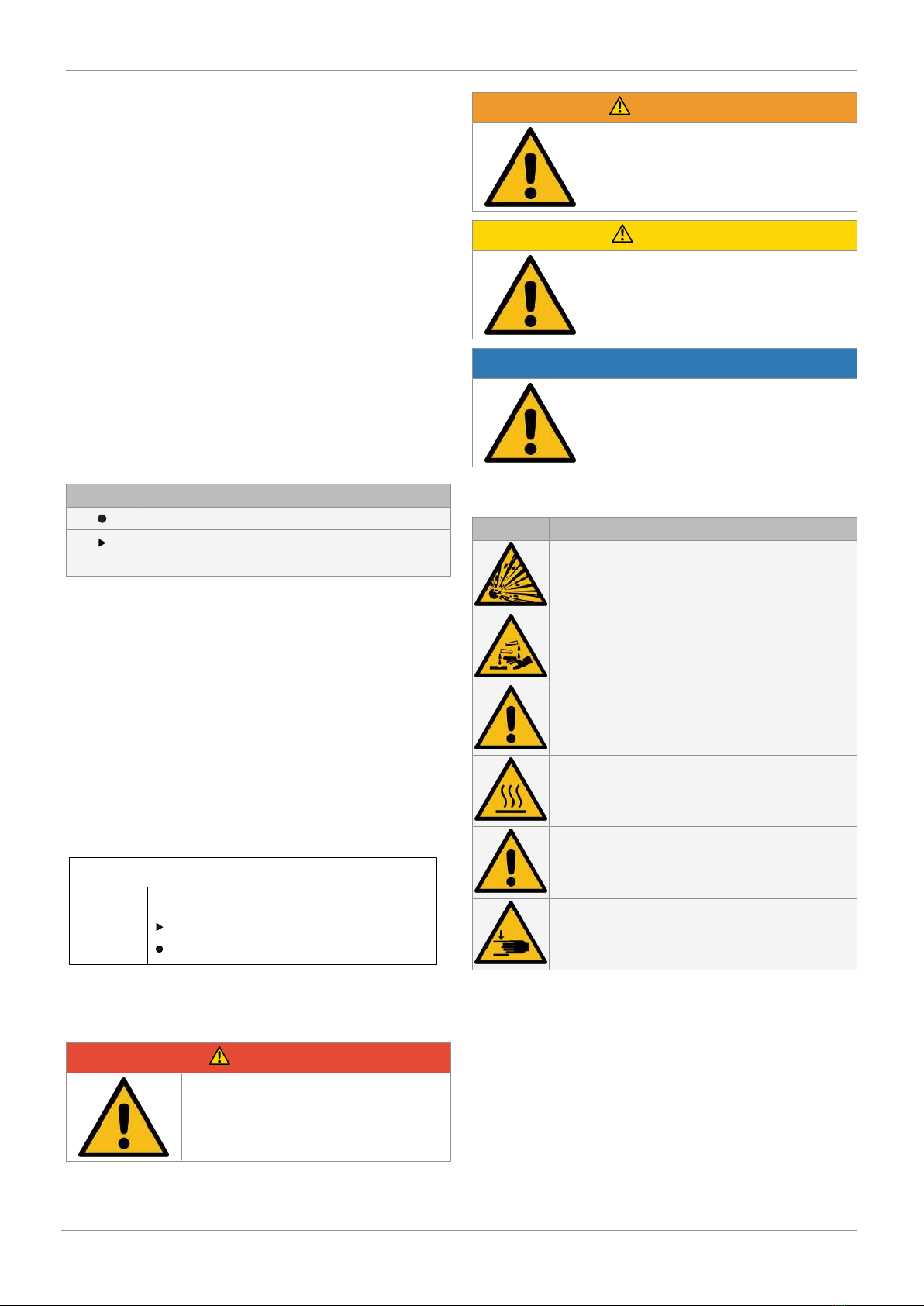
1.4 Warning notes ............................................... 4
2 Safety information ............................................... 5
3 Product description ............................................. 5
3.1 Construction .................................................. 5
3.2 Description ..................................................... 5
3.3 Function ......................................................... 5
3.4 Product label ................................................. 6
3.5 ATEX label ...................................................... 6
4 GEMÜ CONEXO .................................................... 6
5 Correct use .......................................................... 7
5.1 Product without special function X .............. 7
5.2 Product with special function X ................... 7
6 Order data ........................................................... 8
6.1 Order codes ................................................... 8
6.2 Order example - standard version ................ 9
7 Technical data ..................................................... 10
7.1 Medium .......................................................... 10
7.2 Temperature .................................................. 10
7.3 Pressure ......................................................... 10
7.4 Product conformity ....................................... 12
7.5 Mechanical data ............................................ 13
8.1 Actuator flange .............................................. 15
8.2 Body ............................................................... 16
9 Manufacturer's information .................................. 33
9.1 Delivery .......................................................... 33
9.2 Transport ....................................................... 33
9.3 Storage ........................................................... 33
10 Installation in piping ............................................ 33
10.1 Preparing for installation .............................. 33
10.2 Installation location ....................................... 34
10.3 Installation of the standard version ............. 35
10.4 Installation of the ATEX version ................... 36
11 Commissioning .................................................... 36
12 Operation ............................................................. 36
13 Troubleshooting .................................................. 37
14 Inspection and maintenance ................................ 38
14.1 Cleaning the product ..................................... 38
14.2 ATEX version ................................................. 38
14.3 Removing the butterfly valve from the pip-
ing ................................................................... 38
14.4 Presetting the butterfly valves ...................... 39
15 Spare parts .......................................................... 40
15.1 Ordering spare parts ..................................... 40
15.2 Lug .................................................................. 41
15.3 Wafer .............................................................. 42
15.4 Replacement of spare parts ......................... 43
16 Removal from piping ............................................ 44
17 Disposal .............................................................. 44
18 Returns ................................................................ 44
19 EU Declaration of Conformity in accordance with
2014/68/EU (Pressure Equipment Directive) ........ 45
GEMÜ R480 Victoriawww.gemu-group.com 3 / 46

www.gemu-group.com4 / 46GEMÜ R480 Victoria
1 General information
1.1 Information
- The descriptions and instructions apply to the standard ver-
sions. For special versions not described in this document
the basic information contained herein applies in combina-
tion with any additional special documentation.
- Correct installation, operation, maintenance and repair work
ensure faultless operation of the product.
- Should there be any doubts or misunderstandings, the Ger-
man version is the authoritative document.
- Contact us at the address on the last page for staff training
information.
- A supplement to Directive 2014/34/EU (ATEX Directive) is
included with the product, provided that it was ordered in
accordance with ATEX.
1.2 Symbols used
The following symbols are used in this document:
Symbol Meaning
Tasks to be performed
Response(s) to tasks
– Lists
1.3 Definition of terms
Working medium
The medium that flows through the GEMÜ product.
Control function
The possible actuation functions of the GEMÜ product.
Control medium
The medium whose increasing or decreasing pressure causes
the GEMÜ product to be actuated and operated.
1.4 Warning notes
Wherever possible, warning notes are organised according to
the following scheme:
SIGNAL WORD
Type and source of the danger
Possible
symbol for the
specific
danger
Possible consequences of non-observance.
Measures for avoiding danger.
Warning notes are always marked with a signal word and
sometimes also with a symbol for the specific danger.
The following signal words and danger levels are used:
DANGER
Imminent danger!
▶Non-observance can cause death or
severe injury.
WARNING
Potentially dangerous situation!
▶Non-observance can cause death or
severe injury.
CAUTION
Potentially dangerous situation!
▶Non-observance can cause moderate
to light injury.
NOTICE
Potentially dangerous situation!
▶Non-observance can cause damage to
property.
The following symbols for the specific dangers can be used
within a warning note:
Symbol Meaning
Danger of explosion!
Corrosive chemicals!
GEMÜ products without an operator!
Hot plant components!
Use as end-of-line valve!
Risk of crushing!

www.gemu-group.com 5 / 46 GEMÜ R480 Victoria
2 Safety information
The safety information in this document refers only to an indi-
vidual product. Potentially dangerous conditions can arise in
combination with other plant components, which need to be
considered on the basis of a risk analysis. The operator is re-
sponsible for the production of the risk analysis and for com-
pliance with the resulting precautionary measures and re-
gional safety regulations.
The document contains fundamental safety information that
must be observed during commissioning, operation and main-
tenance. Non-compliance with these instructions may cause:
- Personal hazard due to electrical, mechanical and chemical
effects.
- Hazard to nearby equipment.
- Failure of important functions.
- Hazard to the environment due to the leakage of dangerous
substances.
The safety information does not take into account:
- Unexpected incidents and events, which may occur during
installation, operation and maintenance.
- Local safety regulations which must be adhered to by the
operator and by any additional installation personnel.
Prior to commissioning:
1. Transport and store the product correctly.
2. Do not paint the bolts and plastic parts of the product.
3. Carry out installation and commissioning using trained
personnel.
4. Provide adequate training for installation and operating
personnel.
5. Ensure that the contents of the document have been fully
understood by the responsible personnel.
6. Define the areas of responsibility.
7. Observe the safety data sheets.
8. Observe the safety regulations for the media used.
During operation:
9. Keep this document available at the place of use.
10. Observe the safety information.
11. Operate the product in accordance with this document.
12. Operate the product in accordance with the specifications.
13. Maintain the product correctly.
14. Do not carry out any maintenance work and repairs not de-
scribed in this document without consulting the manufac-
turer first.
In cases of uncertainty:
15. Consult the nearest GEMÜ sales office.
3 Product description
3.1 Construction
1
2
3
6
4
5
7
8
8
9
0-1
0-2
10
Item Name Materials
1 Body SG iron 5.3106, epoxy
coated (RAL 5021)
2 Shaft 1.4021
3 Axis 1.4021
4 Disc Various materials (see or-
der data)
5 Liner Various materials (see or-
der data)
6 Threaded plug 1.4021
7 O-ring NBR
8 Support rings PTFE
9 Hexagon head bolts Stainless steel A2-70
0 Earthing kit for ATEX ver-
sion
0-1 Cable lug
0-2 Stranded wire
3.2 Description
The GEMÜ R480 Victoria soft seated metal butterfly valve is
equipped with a bare shaft with top flange in accordance with
EN ISO 5211. The butterfly valve is available in nominal sizes
DN 50 to 300 and in standardized installation lengths ISO
5752/20 | EN 558-1/20 | API 609 category A (DIN 3202 K1) in
wafer and lug body versions.
3.3 Function
The product controls a flowing medium after a manual, pneu-
matic or motorized actuator has been mounted.
3 Product description

www.gemu-group.com6 / 46GEMÜ R480 Victoria
4 GEMÜ CONEXO
3.4 Product label
The product label is located on the valve body. Product label
data (example):
Design in accordance with order data
Item number
Device-specific data
Year of manufacture
The month of manufacture is encoded in the traceability num-
ber and can be obtained from GEMÜ. The product was manu-
factured in Germany.
The operating pressure stated on the product label applies to
a media temperature of 20 °C. The product can be used up to
the maximum stated media temperature. You can find the
pressure/temperature correlation in the technical data.
3.5 ATEX label
The product with special function X is intended for use in po-
tentially explosive areas and is equipped with an ATEX label.
On the butterfly valve there is an additional adhesive label
with the ATEX marking for the butterfly valve with bare shaft:
480 50W332A1ELF05 D09 X
II -/2 G 88326775
II -/2 D
Ex h -/IIB T6 …T3 -/Gb X
Ex h -/IIIC T150°C -/Db X
The ATEX marking applies only to the butterfly valve with bare
shaft. The overall evaluation must be carried out by the plant
operator.
4 GEMÜ CONEXO
The interaction of valve components that are equipped with
RFID chips and an associated IT infrastructure actively in-
crease process reliability.
Thanks to serialization, every valve and every relevant valve
component such as the body, actuator or diaphragm, and
even automation components, can be clearly traced and read
using the CONEXO pen RFID reader. The CONEXO app, which
can be installed on mobile devices, not only facilitates and im-
proves the "installation qualification" process, but also makes
the maintenance process much more transparent and easier
to document. The app actively guides the maintenance techni-
cian through the maintenance schedule and directly provides
him with all the information assigned to the valve, such as
test reports, testing documentation and maintenance histor-
ies. The CONEXO portal acts as a central element, helping to
collect, manage and process all data.
For further information on GEMÜ CONEXO please visit:
www.gemu-group.com/conexo

www.gemu-group.com 7 / 46 GEMÜ R480 Victoria
5 Correct use
DANGER
Danger of explosion!
▶Risk of severe injury or death.
●Do not use the product in potentially
explosive zones.
●Only use the product in potentially ex-
plosive zones confirmed in the declara-
tion of conformity.
WARNING
Improper use of the product!
▶Risk of severe injury or death
▶Manufacturer liability and guarantee will be void
●Only use the product in accordance with the operating
conditions specified in the contract documentation and in
this document.
The product is designed for installation in piping systems and
for controlling a working medium.
●Use the product in accordance with the technical data.
5.1 Product without special function X
The product is not intended for use in potentially explosive
areas.
5.2 Product with special function X
With the special version X order option, the product is inten-
ded for use in potentially explosive areas in zone 1 with gases,
mists or vapours and zone 21 with combustible dusts in ac-
cordance with EU Directive 2014/34/EU (ATEX).
The product has the following explosion protection marking:
Gas: II -/2 G Ex h -/IIB T6 …T3 -/Gb X
Dust: II -/2 D Ex h -/IIIC T150°C -/Db X
The product has been developed in compliance with the fol-
lowing harmonized standards:
- EN 1127-1:2011
- ISO 80079-36:2016
- ISO 80079-37:2016
The product can be used in the following ambient temperat-
ure ranges: -10 °C to +70 °C
For use in potentially explosive areas, the following special
conditions or operation limits must be observed:
Index X is applied to the ATEX marking.
The following special conditions must be complied with:
- Temperature class depending on the temperature of the
conveyed medium and the clock frequency
- Not permissible as an end-of-line valve
5 Correct use

6 Order data
Other configurations available on request. Please check the availability with GEMÜ before ordering.
Products ordered with bold marked ordering options are so-called preferred series. Depending on the nominal size, these are
available more quickly.
Order codes
1 Type Code
Butterfly valve, bare shaft,
body with C5-M coating (min. 250 µm) and
integrated leakage groove, blow-out proof shaft with
dust protection,
multiple bearings through PTFE bushing,
multiple sealing system with insertion slope,
material easy to read when installed
R480
2 DN Code
DN 25 25
DN 32 32
DN 40 40
DN 50 50
DN 65 65
DN 80 80
DN 100 100
DN 125 125
DN 150 150
DN 200 200
DN 250 250
DN 300 300
DN 350 350
DN 400 400
DN 450 450
DN 500 500
DN 600 600
3 Body configuration Code
Flange-mounted design (lug),
face-to-face dimension FTF EN 558 series 20
L
Double flange design (U section),
face-to-face dimension FTF EN 558, series 20
U
Intermediate flange design (wafer),
face-to-face dimension FTF EN 558 series 20
W
4 Operating pressure Code
3 bar 0
6 bar 1
10 bar 2
16 bar 3
5 Connection type Code
PN 6/flange EN 1092, face-to-face dimension FTF EN
558 series 20
1
PN 10/flange EN 1092, face-to-face dimension FTF EN
558 series 20
2
PN 16/flange EN 1092, face-to-face dimension FTF EN
558 series 20
3
ANSI B16.5, class 150, face-to-face dimension FTF EN
558 series 20
D
5 Connection type Code
Flange BS 10 Tab E,
face-to-face dimension FTF EN 558, series 20
S
Flange AS 2129 Tab D,
face-to-face dimension FTF EN 558, series 20
T
Flange AS 2129 Tab E,
face-to-face dimension FTF EN 558, series 20
U
Flange BS 10 Tab D,
face-to-face dimension FTF EN 558, series 20
H
JIS 10 K,
face-to-face dimension FTF EN 558, series 20
G
JIS 16 K, face-to-face dimension FTF EN 558, series 20 J
6 Body material Code
EN-GJS-400-15 (GGG-40), epoxy coated 250 μm 2
EN-GJS-400-18-LT (GGG-40.3), epoxy coated 250 µm 3
7 Disc material Code
1.4408 A
1.4408, polished, roughness Ra 0.6–3.2, except disc
marking
B
1.4408, HALAR coated C
1.4469, SUPER DUPLEX D
EN-GJS-400-15 (GGG-40), epoxy coated E
EN-GJS-400-15 (GGG-40), HALAR coated P
EN-GJS-400-15 (GGG-40), RILSAN PA11 coated R
2.0975/CC333G G
1.4435/ASTM A351/CF3M/AISI 316L I
8 Shaft material Code
1.4021 1
9 Shut-off seal material Code
EPDM E
SBR-AB/P (abrasion resistant) F
CSM H
NR (FDA/1935-2004 certification), white AB/W I
NBR (DVGW Gas certification) J
EPDM (FDA/1935-2004 certification), white M
NBR N
FKM + O
EPDM-SHT (steam) T
NBR (FDA/1935-2004 certification), white U
FKM V
EPDM (drinking water compliant) W
EPDM-HT (FDA/1935-2004 certification) Z
10 Liner fixing Code
Liner bonded into body B
Loose liner L
6 Order data
www.gemu-group.com8 / 46GEMÜ R480 Victoria

11 Type of design Code
Without
Media wetted area cleaned to ensure suitability for paint
applications,
parts sealed in plastic bag
0101
Valve free of oil and grease, media wetted area cleaned
and packed in PE bag
0107
Stainless steel valve disc,
mechanically polished to 1.6 µm and electropolished,
spigot internally polished to 1.6 µm
1782
Butterfly valve body powder coated, RAL 5015, sky blue 1892
Butterfly valve body powder coated, RAL 1023, traffic
yellow
1925
Mounting parts in A4 quality.
Caution! Danger of galling! Customer must provide for
this!
5143
Thermal separation between actuator and valve body
via mounting kit
5222
Thermal separation between actuator and valve body
via dew point barrier
5226
Alu product label, black anodized, lasered marking,
riveted to the body
6061
12 Special version Code
Without
ACS certification A
BELGAQUA certification B
DVGW Water certification D
Country of origin Germany E
DVGW Gas certification G
NSF 61 water certification N
Special version for oxygen
maximum medium temperature: 60 °C,
Media wetted materials cleaned, and grease and seal
with BAM testing
O
ASME B31.3 P
DNV GL certification S
WRAS certification W
ATEX certification X
ATEX certification (in the piping system) Y
13 CONEXO Code
Without
Integrated RFID chip for electronic identification and
traceability
C
Order example - standard version
Ordering option Code Description
1 Type R480 Butterfly valve, bare shaft,
body with C5-M coating (min. 250 µm) and
integrated leakage groove, blow-out proof shaft with dust protection,
multiple bearings through PTFE bushing,
multiple sealing system with insertion slope,
material easy to read when installed
2 DN 80 DN 80
3 Body configuration W Intermediate flange design (wafer),
face-to-face dimension FTF EN 558 series 20
4 Operating pressure 3 16 bar
5 Connection type 3 PN 16/flange EN 1092, face-to-face dimension FTF EN 558 series 20
6 Body material 2 EN-GJS-400-15 (GGG-40), epoxy coated 250 μm
7 Disc material A 1.4408
8 Shaft material 1 1.4021
9 Shut-off seal material E EPDM
10 Liner fixing L Loose liner
11 Type of design Without
12 Special version Without
13 CONEXO Without
6 Order data
www.gemu-group.com 9 / 46 GEMÜ R480 Victoria

7 Technical data
7.1 Medium
Working medium: Gaseous and liquid media which have no negative impact on the physical and chemical properties
of the disc and seat material.
7.2 Temperature
Media temperature: -10 — 160 °C
Depending on the liner and disc material or the type of liner fixing
J
F
M
W
N
(7)I
E
Z
H
T
V
U
O
Disc material (code R)
NBR (code J)
SBR (AB/P) (code F)
NR (AB/W) (code I)
EPDM, white (code M)
NBR (code N)
NBR, white (code U)
EPDM (code W)
EPDM (code E)
CSM (code H)
EPDM HT (code Z)
FPM (code V)
EPDM SHT (code T)
FKM+ (code O)
Disc material (code E)
Liner material
-10 0 10 20 30 40 50 60 70 80 90 100 110 120 130 140 150 160
Temperature [°C]
Not recommended for permanent temperature
FKM material not suitable for water/steam applications above 100 °C,
Observe Pressure/Temperature diagram.
Ambient temperature: -10 — 70 °C
Storage temperature: -20 — 40 °C
7.3 Pressure
Operating pressure: DN 25–200: 0–16 bar
DN 250–600: 0–10 bar
Observe pressure/temperature diagram
Use as an end-of-line valve:
DN 25–200: 10 bar
DN 250–600: 6 bar
Vacuum: Can be used up to a vacuum of 800 mbar (abs) with replaceable liner or with bonded liner up to a
vacuum of 2 mbar (abs) through a leakage rate at 10-3[mbar l/sec]
These values apply to room temperature and air. The values may deviate for other media and other
temperatures.
www.gemu-group.com10 / 46GEMÜ R480 Victoria
7 Technical data

Pressure/temperature
diagram:
DN 50 - 200
DN 250 - 600
-20 200 40 60 80 100 120 140 160 180 200
0
2
4
6
8
10
12
14
16
18
Pressure [bar]
Temperature [°C]
DN 25–200
DN 250–600
Pressure rating: PN 3
PN 6
PN 10
PN 16
Kv values: DN PS Kv values at opening angle
[bar] 20° 30° 40° 50° 60° 70° 80° 90°
25 16 0.7 2.0 4.1 7.2 11.0 14.5 16.6 17.2
40 16 2.5 7.0 14.4 25.1 38.3 50.6 57.8 60.0
50 16 3.0 9.0 20.0 33.0 65.0 110.0 124.0 125.0
65 16 9.0 15.0 30.0 64.0 118.0 195.0 214.0 222.0
80 16 19.0 40.0 66.0 117.0 196.0 321.0 353.0 363.0
100 16 29.0 75.0 137.0 213.0 316.0 487.0 584.0 618.0
125 16 48.0 100.0 185.0 315.0 550.0 895.0 1060.0 1120.0
150 16 60.0 150.0 281.0 450.0 789.0 1280.0 1630.0 1730.0
200 3/16 110.0 281.0 472.0 759.0 1480.0 2880.0 3710.0 3900.0
250 3/10 200.0 444.0 738.0 1190.0 2110.0 3880.0 5180.0 5410.0
300 3/10 250.0 682.0 1060.0 1670.0 3120.0 6360.0 8620.0 8930.0
350 3/10 466.0 1036.0 1721.0 2767.0 4397.0 6803.0 9097.0 9494.0
400 3/10 644.0 1431.0 2376.0 3820.0 6072.0 9394.0 12561.0 13110.0
450 3/10 1039.0 2308.0 3834.0 6163.0 9796.0 15154.0 20264.0 21149.0
500 3/10 1083.0 2406.0 3997.0 6425.0 10213.0 15800.0 21127.0 22050.0
600 3/10 1563.0 3473.0 5770.0 9276.0 14744.0 22809.0 30500.0 31832.0
Kv values in m³/h
When the opening angle is below 30° no regulation should be made!
GEMÜ R480 Victoriawww.gemu-group.com 11 / 46
7 Technical data

7.4 Product conformity
Pressure equipment
standards:
ASME GEMÜ B31.3
2014/68/EU
The butterfly valve fulfils the technical requirements of pressure equipment categories I and II and
can be used under the following conditions.
Areas of use for R480 butterfly valve as in-line valve
(classification as per Pressure Equipment Directive 2014/68/EC Article 4 and Annex II)
Media of fluid group 1 (dangerous) Media of fluid group 2 (other)
PS Gases
(Section 4 (1) c) i),
diagram 6)
Liquids
(Section 4 (1) c) ii),
diagram 8)
Gases
(Section 4 (1) c) i),
diagram 7)
Liquids
(Section 4 (1) c) ii),
diagram 9)
16 DN 25–200 DN 25–200* DN 25–200* DN 25–200*
10 DN 25–350 DN 25–600 DN 25–500 DN 25–600
6DN 25–350 DN 25–600 DN 25–600 DN 25–600
3DN 25–350 DN 25–600 DN 25–600 DN 25–600
* Limit of the technical specification
When used as an end-of-line valve, a mating flange must be fitted.
Special conditions of use as an end-of-line valve: See section 7.3.
Food: FDA
Regulation (EC) No. 1935/2004
Drinking water: DVGW
ACS
WRAS
Belgaqua
NSF
Oxygen: BAM compliant, the product is suitable for application with oxygen
Gas: DVGW
Ship approval: DNV GL
Explosion protection: ATEX (2014/34/EU), order code Special version X and Y
ATEX marking: Special function code X
Gas: II -/2 G Ex h -/IIB T6...T3 -/Gb X
Dust: II -/2D Ex h -/IIIC T150°C -/Db X
Special function code Y
Gas: II 2 G Ex h IIC/IIB T6 ... T3 Gb X
Dust: II 2 D Ex h IIIC T150 °C Db X
SIL: Product description: GEMÜ butterfly valve R480 Victoria®
Type of valve: A
Safety function: The safety function of the Butterfly Valve is to open on
trip, close on trip, or close with a tight shutoff on trip.
HFT (Hardware Fault Tolerance): 0
MTTR (Mean Time To Restoration): 48 hours
www.gemu-group.com12 / 46GEMÜ R480 Victoria
7 Technical data

TA Luft (German Clean
Air Act):
The product meets the following requirements under the max. permissible operating conditions:
- Tightness or compliance with the specific leak rate within the sense of TA-Luft as well as VDI
2440
- Compliance with the requirements in accordance with DIN EN ISO 15848-1, Table C.2, Class BH
7.5 Mechanical data
Torques: DN PS
3 bar 6 bar 10 bar 16 bar *
25 - - - 4.0
40 - - - 7.0
50 3.0 5.0 7.0 9.0
65 8.0 10.0 13.0 15.0
80 10.0 15.0 20.0 25.0
100 15.0 20.0 30.0 40.0
125 25.0 35.0 45.0 60.0
150 40.0 50.0 80.0 100.0
200 100.0 - - 160.0
250 140.0 - 200.0 -
300 200.0 - 330.0 -
350 255.0 - 430.0 -
400 580.0 - 1035.0 -
450 600.0 - 1150.0 -
500 860.0 - 1250.0 -
600 1441.0 - 2140.0 -
Torques in Nm
* Standard
Working medium water (20 °C) and optimal operating conditions
Tightening torques: Bolt size Tightening torque [Nm]
M5 5–6
M6 10–11
M8 23–25
M10 48–52
M12 82–86
M14 132–138
M16 200–210
M20 390–410
M24 675–705
GEMÜ R480 Victoriawww.gemu-group.com 13 / 46
7 Technical data

Weight: DN Wafer Lug U section
25 1.2 - -
40 1.5 - -
50 1.7 2.2 -
65 2.5 2.9 -
80 3.2 4.4 -
100 4.4 6.2 -
125 5.9 8.1 -
150 7.7 10.1 -
200 13.9 18.4 -
250 19.6 28.7 -
300 27.3 36.8 -
350 48.0 66.0 -
400 72.0 110.0 107.0
450 95.0 - 125.0
500 120.0 - 164.0
600 192.0 - 261.0
Weights in kg
www.gemu-group.com14 / 46GEMÜ R480 Victoria
7 Technical data

8 Dimensions
8.1 Actuator flange
a
øb1
□G
DN 25, 40
DN 350 - 600
øy1
E
a
ø
b2
ø
b1
□
G
ø
y1
ø
y2
DN 50 - 65,
DN 125 - 300
□
G
ø
y1
ø
b1
DN 80 - 100
a
DN ISO 5211 a øb1 øy1 øb2 øy2 E □G Code
PS3 PS10/
PS16
PS3 PS10/
PS16
25 F05 50.0 50.0 7.0 - - - 19.0 - 9.0 05 D09
40 F05 50.0 50.0 7.0 - - - 19.0 - 9.0 05 D09
50 F03 | F05 65.0 36.0 6.0 50.0 7.0 - 19.0 - 9.0 05 D09
65 F03 | F05 65.0 36.0 6.0 50.0 7.0 - 19.0 - 11.0 05 D11
80 F05 65.0 50.0 7.0 - - - 19.0 - 11.0 05 D11
100 F05 65.0 50.0 7.0 - - - 19.0 - 14.0 05 D14
125 F05 | F07 90.0 50.0 7.0 70.0 9.0 - 25.0 - 17.0 07 D17
150 F05 | F07 90.0 50.0 7.0 70.0 9.0 - 25.0 - 17.0 07 D17
200 F07 | F10 125.0 70.0 9.0 102.0 11.0 25.0 32.0 17.0 22.0 10 D22
250 F07 | F10 125.0 70.0 9.0 102.0 11.0 25.0 32.0 17.0 22.0 10 D22
300 F07 | F10 125.0 70.0 9.0 102.0 11.0 25.0 32.0 17.0 22.0 10 D22
350 F12 130.0 125.0 13.0 - - 28.0 28.0 22.0 27.0 12 D27
400 F14 160.0 140.0 17.0 - - 28.0 37.0 27.0 36.0 14 D36
450 F14 160.0 140.0 17.0 - - 28.0 37.0 27.0 36.0 14 D36
500 F14 160.0 140.0 17.0 - - 28.0 37.0 27.0 36.0 14 D36
600 F16 200.0 165.0 21.0 - - 37.0 47.0 36.0 46.0 16 D46
Dimensions in mm
GEMÜ R480 Victoriawww.gemu-group.com 15 / 46
8 Dimensions

8.2 Body
8.2.1 Wafer body configuration
Ø
D
B1
A
B
F
FTF
ØS
H
I
Ø
D1
B
A
ØD
B1
F
FTF I
H
ØS
DN 125 - 600DN 25 - 100
DN A B B1 ØD ØD1 F FTF H* ØS I
25 100.0 141.3 41.3 59.5 88.6 12.0 25.0 16.0 26.5 0.5
32 120.0 173.8 53.8 75.8 109.8 12.0 43.0 24.5 41.5 4.0
40 120.0 173.8 53.8 75.8 109.8 12.0 43.0 24.5 41.5 4.0
50 120.0 182.0 62.0 90.0 118.0 12.0 43.0 29.0 52.0 5.0
65 137.0 218.0 81.0 108.0 133.0 12.0 46.0 48.0 67.0 10.0
80 145.0 231.0 87.0 130.0 141.0 12.0 46.0 68.0 82.0 18.0
100 166.0 271.0 105.0 150.0 163.0 14.0 52.0 88.0 102.0 25.0
125 187.0 304.0 117.0 175.0 120.0 16.0 56.0 114.0 127.0 35.0
150 200.0 332.0 132.0 207.0 129.0 16.0 56.0 141.0 152.0 48.0
200 240.0 413.0 173.0 263.0 157.0 17.0 60.0 193.0 202.0 71.0
250 265.0 466.0 201.0 317.0 185.0 17.0 68.0 242.0 252.0 92.0
300 290.0 531.0 241.0 366.0 164.0 17.0 78.0 291.0 302.0 112.0
350 321.0 587.0 266.0 440.0 440.0 15.0 78.0 329.0 337.4 130.0
400 347.0 655.0 308.0 485.0 485.0 20.0 102.0 379.0 391.4 145.0
450 372.0 705.0 333.0 541.0 541.0 20.0 114.0 428.0 441.4 164.0
500 398.0 756.0 358.0 600.0 600.0 20.0 127.0 478.0 493.4 183.5
600 470.0 912.0 442.0 700.0 700.0 24.0 154.0 574.0 593.4 220.0
Dimensions in mm
* Please note dimension H to prevent disc binding on internal pipe
Please note: chamfer flanges for plastic pipelines if necessary
www.gemu-group.com16 / 46GEMÜ R480 Victoria
8 Dimensions

8.2.1.1 Threaded hole
W
G
Y
Y
Y
Threaded hole (detail Y)
DN Connection type code 1)
2 3 D
G W G W G W
450 M24 46 M27 46 Ø 31,7 -
Dimensions in mm
1) Connection type
Code 2: PN 10/flange EN 1092, face-to-face dimension FTF EN 558 series 20
Code 3: PN 16/flange EN 1092, face-to-face dimension FTF EN 558 series 20
Code D: ANSI B16.5, class 150, face-to-face dimension FTF EN 558, series 20, For lug bodies/threaded holes with UNC thread
GEMÜ R480 Victoriawww.gemu-group.com 17 / 46
8 Dimensions

8.2.1.2 Connections
ØG
ØG
W°
W°
n-ø
y
y
Connection EN1092, ANSI B16.5
DN INCH Connection (code)
EN1092-1 PN6
(code 1)
EN1092-1 PN10
(code 2)
EN1092-1 PN16
(code 3)
ANSI B16.5/CL150
(code D)
DIN ANSI w° n ØG y w° n ØG y w° n ØG y w° n ØG y
25 1" 90 4 75.0 M10 90 4 85.0 M12 90 4 85.0 M12 90 4 79.0 1/2"
32 1¼" 90 4 90.0 M12 90 4 100.0 M16 90 4 100.0 M16 90 4 89.0 1/2"
40 1½" 90 4 100.0 M12 90 4 110.0 M16 90 4 110.0 M16 90 4 98.0 1/2"
50 2" 90 4 110.0 14.0 90 4 125.0 18.0 90 4 125.0 18.0 90 4 120.6 19.0
65 2½" 90 4 130.0 14.0 45 8 145.0 18.0 45 8 145.0 18.0 90 4 139.7 19.0
80 3" 90 4 150.0 18.0 45 8 160.0 18.0 45 8 160.0 18.0 90 4 152.4 19.0
100 4" 90 4 170.0 18.0 45 8 180.0 18.0 45 8 180.0 18.0 45 8 190.5 19.0
125 5" 45 8 200.0 18.0 45 8 210.0 18.0 45 8 210.0 18.0 45 8 215.9 22.2
150 6" 45 8 225.0 18.0 45 8 240.0 22.0 45 8 240.0 22.0 45 8 241.3 22.2
200 8" 45 8 280.0 18.0 45 8 295.0 22.0 30 12 295.0 22.0 45 8 298.5 22.2
250 10" 30 12 335.0 18.0 30 12 350.0 22.0 30 12 355.0 26.0 30 12 362.0 25.4
300 12" 30 12 395.0 22.0 30 12 400.0 22.0 30 12 410.0 26.0 30 12 431.8 25.4
350 14" - - - - 22.5 16 460.0 M20 22.5 16 470.0 M24 30 12 476.0 1"
400 16" - - - - 22.5 16 515.0 M24 22.5 16 525.0 M27 22.5 16 540.0 1"
450 18" - - - - 18 20 565.0 M24 18 20 585.0 M27 22.5 16 578.0 1⅛"
500 20" - - - - 18 20 620.0 M24 18 20 650.0 M30 18 20 635.0 1⅛"
600 24" - - - - 18 20 725.0 M27 18 20 770.0 M33 18 20 749.0 1¼"
Dimensions in mm
n = number of bolts
www.gemu-group.com18 / 46GEMÜ R480 Victoria
8 Dimensions

ØG
ØG
W°
W°
n-ø
y
y
Connection AS2129, BS10
DN INCH Connection (code)
AS 2129 D (code T) AS 2129 E (code U) BS10 D (code H) BS10 E (code S)
DIN ANSI w° n ØG y w° n ØG y w° n ØG y w° n ØG y
25 1" 90 4 83.0 M12 90 4 83.0 M12 90 4 83.0 M12 90 4 83.0 M12
32 1¼" 90 4 87.0 M12 90 4 87.0 M12 90 4 87.0 M12 90 4 87.0 M12
40 1½" 90 4 98.0 M12 90 4 98.0 M12 90 4 98.0 M12 90 4 98.0 M12
50 2" 90 4 114.0 18.0 90 4 114.0 18.0 90 4 114.3 17.5 90 4 114.3 17.5
65 2½" 90 4 127.0 18.0 90 4 127.0 18.0 90 4 127.0 17.5 90 4 127.0 17.5
80 3" 90 4 146.0 18.0 90 4 146.0 18.0 90 4 146.1 17.5 90 4 146.1 17.5
100 4" 90 4 178.0 18.0 45 8 178.0 18.0 90 4 177.8 17.5 45 8 177.8 17.5
125 5" 45 8 210.0 18.0 45 8 210.0 18.0 45 8 209.6 17.5 45 8 209.6 17.5
150 6" 45 8 235.0 18.0 45 8 235.0 22.0 45 8 235.0 17.5 45 8 235.0 20.6
200 8" 45 8 292.0 18.0 45 8 292.0 22.0 45 8 292.1 17.5 45 8 292.1 20.6
250 10" 45 8 356.0 22.0 30 12 356.0 22.0 45 8 355.6 22.2 30 12 355.6 22.2
300 12" 30 12 406.0 22.0 30 12 406.0 26.0 30 12 406.4 22.2 30 12 406.4 25.4
350 14" 30 12 470.0 M22 30 12 470.0 M27 30 12 470.0 M22 30 12 470.0 M27
400 16" - - - - - - - - - - - - - - - -
450 18" - - - - 22.5 16 584.0 M24 - - - - 22.5 16 584.0 M24
500 20" - - - - - - - - - - - - - - - -
600 24" 22.5 16 756.0 M27 22.5 16 756.0 M30 22.5 16 756.0 M27 22.5 16 756.0 M30
Dimensions in mm
n = number of bolts
GEMÜ R480 Victoriawww.gemu-group.com 19 / 46
8 Dimensions

ØG
ØG
W°
W°
n-ø
y
y
Connection JIS K10, K16
DN INCH Connection (code)
JIS-K10 (code G) JIS-K16 (code J)
DIN ANSI w° n ØG y w° n ØG y
25 1" 90 4 90.0 M16 90 4 90.0 M16
32 1¼" 90 4 100.0 M16 90 4 100.0 M16
40 1½" 90 4 105.0 M16 90 4 105.0 M16
50 2" 90 4 120.0 19.0 45 8 120.0 19.0
65 2½" 90 4 140.0 19.0 45 8 140.0 19.0
80 3" 45 8 150.0 19.0 45 8 160.0 23.0
100 4" 45 8 175.0 19.0 45 8 185.0 23.0
125 5" 45 8 210.0 23.0 - - - -
150 6" 45 8 240.0 23.0 - - - -
200 8" 30 12 290.0 23.0 30 12 305.0 25.0
250 10" 30 12 355.0 25.0 - - - -
300 12" 22,5 16 400.0 25.0 - - - -
350 14" --------
400 16" 22.5 16 510.0 M24 - - - -
450 18" 18 20 565.0 M24 - - - -
500 20" 18 20 620.0 M24 - - - -
600 24" 15 24 730.0 M30 - - - -
Dimensions in mm
n = number of bolts
www.gemu-group.com20 / 46GEMÜ R480 Victoria
8 Dimensions
Other manuals for R480 Victoria
1
Table of contents
Other GEM Control Unit manuals
Popular Control Unit manuals by other brands

GE
GE Evolution Series E9000 Installation, operation and maintenance manual

Dometic
Dometic AH Series Installation and operating manual

Mitsubishi
Mitsubishi MELSEC A1S64AD user manual

Bosch
Bosch Security Systems Blue Line A1-CC quick start guide

Dickey-John
Dickey-John Land Manager SE manual

Danfoss
Danfoss AB-QM Series installation guide