GEM M75 User manual

GEMÜ M75
Electrically operated solenoid valve
Operating instructions
EN
further information
webcode: GW-M75

All rights including copyrights or industrial property rights are expressly reserved.
Keep the document for future reference.
© GEMÜ Gebr. Müller Apparatebau GmbH & Co. KG
11.01.2022
www.gemu-group.com2 / 29GEMÜ M75

Contents
1 General information ............................................. 4
1.1 Information .................................................... 4
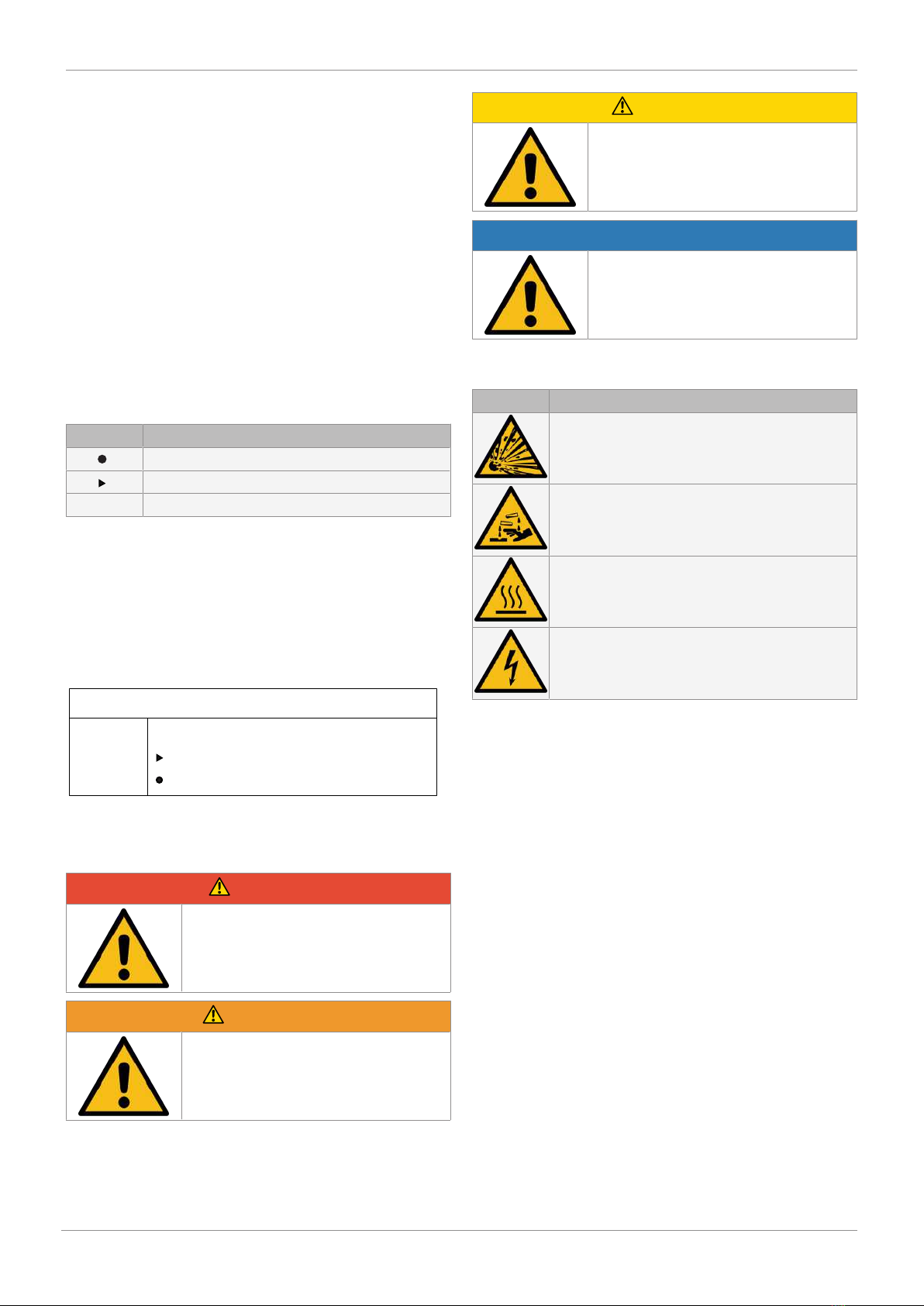
1.2 Symbols used ................................................ 4
1.3 Definition of terms ........................................ 4
1.4 Warning notes ............................................... 4
2 Safety information ............................................... 5
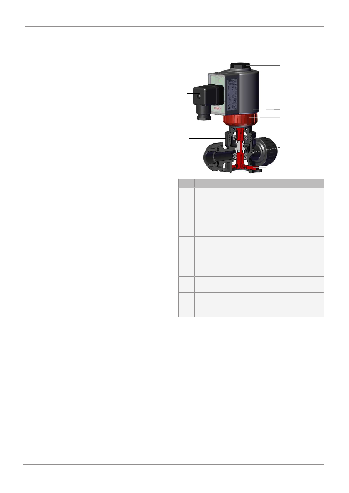
3 Product description ............................................. 5
4 GEMÜ CONEXO .................................................... 6
5 Correct use .......................................................... 7
6 Order data ........................................................... 8
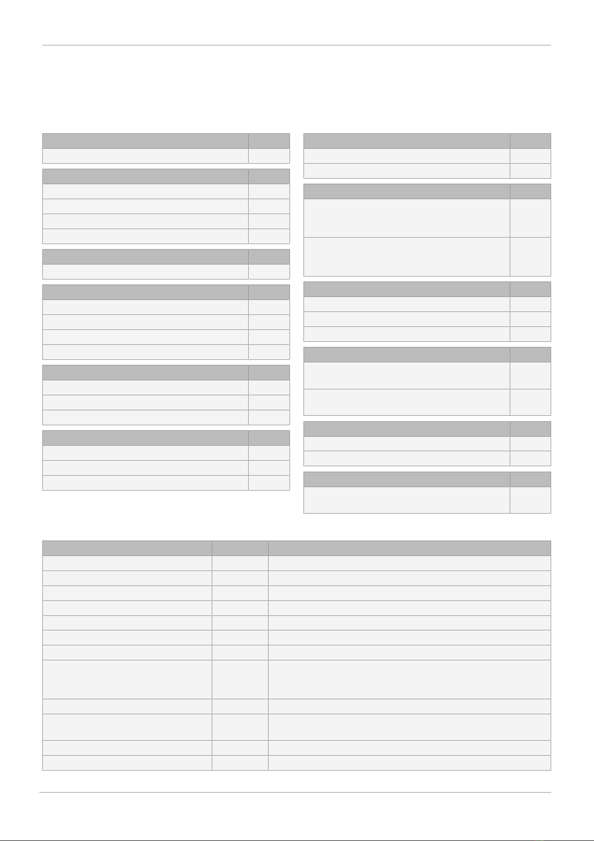
7 Technical data ..................................................... 9
7.1 Medium .......................................................... 9
7.2 Temperature .................................................. 9
7.3 Pressure ......................................................... 9
7.4 Product conformity ....................................... 10
7.5 Mechanical data ............................................ 10
7.6 Electrical data ................................................ 10
8 Dimensions .......................................................... 12
8.1 Actuator ......................................................... 12
8.2 Valve body ..................................................... 12
8.3 Mounting dimensions ................................... 15
9 Manufacturer's information .................................. 16
9.1 Delivery .......................................................... 16
9.2 Transport ....................................................... 16
9.3 Storage ........................................................... 16
9.4 Scope of delivery ........................................... 16
10 Installation in piping ............................................ 16
10.1 Preparing for installation .............................. 16
10.2 Flow direction ................................................ 17
10.3 Installation position ....................................... 17
10.4 Installation with union ends .......................... 18
10.5 Installation with butt weld spigots ............... 18
10.6 Installation with threaded sockets ............... 18
10.7 Installation with solvent cement sockets .... 18
10.8 Orientation of the actuator ........................... 18
11 Electrical connection ........................................... 19
12 Commissioning .................................................... 19
13 Operation ............................................................. 20
13.1 Normal operation .......................................... 20
13.2 Manual override ............................................. 20
14 Inspection and maintenance ................................ 20
14.1 Replacing the actuator .................................. 20
14.2 Cleaning the product ..................................... 21
14.3 Spare parts .................................................... 22
15 Troubleshooting .................................................. 23
16 Removal from piping ............................................ 24
17 Disposal .............................................................. 24
18 Returns ................................................................ 24
19 Declaration of Incorporation according to
2006/42/EC (Machinery Directive) ....................... 25
20 Manufacturer's declaration according to 2014/68/
EU (Pressure Equipment Directive) ...................... 26
21 Declaration of conformity according to 2014/30/
EU (EMC Directive) ............................................... 27
22 Declaration of conformity according to 2014/35/
EU (Low Voltage Directive) ................................... 28
GEMÜ M75www.gemu-group.com 3 / 29

www.gemu-group.com4 / 29GEMÜ M75
1 General information
1.1 Information
•The descriptions and instructions apply to the standard ver-
sions. For special versions not described in this document
the basic information contained herein applies in combina-
tion with any additional special documentation.
•Correct installation, operation, maintenance and repair work
ensure faultless operation of the product.
•Should there be any doubts or misunderstandings, the Ger-
man version is the authoritative document.
•Contact us at the address on the last page for staff training
information.
1.2 Symbols used
The following symbols are used in this document:
Symbol Meaning
Tasks to be performed
Response(s) to tasks
– Lists
1.3 Definition of terms
Working medium
The medium that flows through the GEMÜ product.
1.4 Warning notes
Wherever possible, warning notes are organised according to
the following scheme:
SIGNAL WORD
Type and source of the danger
Possible
symbol for the
specific
danger
Possible consequences of non-observance.
Measures for avoiding danger.
Warning notes are always marked with a signal word and
sometimes also with a symbol for the specific danger.
The following signal words and danger levels are used:
DANGER
Imminent danger!
▶Non-observance can cause death or
severe injury.
WARNING
Potentially dangerous situation!
▶Non-observance can cause death or
severe injury.
CAUTION
Potentially dangerous situation!
▶Non-observance can cause moderate
to light injury.
NOTICE
Potentially dangerous situation!
▶Non-observance can cause damage to
property.
The following symbols for the specific dangers can be used
within a warning note:
Symbol Meaning
Danger of explosion
Corrosive chemicals!
Hot plant components!
Risk of electric shock

www.gemu-group.com 5 / 29 GEMÜ M75
2 Safety information
The safety information in this document refers only to an indi-
vidual product. Potentially dangerous conditions can arise in
combination with other plant components, which need to be
considered on the basis of a risk analysis. The operator is re-
sponsible for the production of the risk analysis and for com-
pliance with the resulting precautionary measures and re-
gional safety regulations.
The document contains fundamental safety information that
must be observed during commissioning, operation and main-
tenance. Non-compliance with these instructions may cause:
•Personal hazard due to electrical, mechanical and chemical
effects.
•Hazard to nearby equipment.
•Failure of important functions.
•Hazard to the environment due to the leakage of dangerous
materials.
The safety information does not take into account:
•Unexpected incidents and events, which may occur during
installation, operation and maintenance.
•Local safety regulations which must be adhered to by the
operator and by any additional installation personnel.
Prior to commissioning:
1. Transport and store the product correctly.
2. Do not paint the bolts and plastic parts of the product.
3. Carry out installation and commissioning using trained
personnel.
4. Provide adequate training for installation and operating
personnel.
5. Ensure that the contents of the document have been fully
understood by the responsible personnel.
6. Define the areas of responsibility.
7. Observe the safety data sheets.
8. Observe the safety regulations for the media used.
During operation:
9. Keep this document available at the place of use.
10. Observe the safety information.
11. Operate the product in accordance with this document.
12. Operate the product in accordance with the specifications.
13. Maintain the product correctly.
14. Do not carry out any maintenance work and repairs not de-
scribed in this document without consulting the manufac-
turer first.
In cases of uncertainty:
15. Consult the nearest GEMÜ sales office.
3 Product description
3.1 Construction
1
2
3
4
5
7
9
6
8
Item Name Materials
1 Transparent cover with
LED status indication
PC
2 Plug PA
3 Valve body PVC-U, PVDF, PP
4 M16x1 thread for position
indicator
5 Electromagnetic actuator PP
6 CONEXO RFID chip on the
actuator
7 Union nut (service/solen-
oid replacement)
PP
8 CONEXO RFID chip on the
valve body
9 Manual override (only with
control function 1 (NC))
Seal materials EPDM, FKM, FEP
3.2 Description
The GEMÜ M75 directly controlled 2/2-way process solenoid
valve has innovative double bellows as a seal, with which the
pressure forces can be compensated. The plastic encapsu-
lated compact coil is available in several supply voltages. O-
rings in various designs ensure hermetic separation between
medium and actuator. The valve is suitable for liquid and
gaseous media in open/close applications with short operat-
ing times. The GEMÜ M75 has a manual override and an en-
ergy-saving reduction in holding current as standard.
3 Product description

www.gemu-group.com6 / 29GEMÜ M75
4 GEMÜ CONEXO
3.3 Function
Fig.1: Sectional view of control function 1 (NC)
The valve fulfils a simple, directly controlled Open/Close func-
tion. Medium pressure is used for pressure compensation.
Applying medium pressure produces opposing tensile forces
on the bellows and throttle element that ultimately cancel
each other out. The installed compression spring serves to
ensure safe sealing and opening at the seat. Activating the
solenoid produces an imbalance of power in the valve centre
axis that opens and closes the valve. Upon deactivating the
magnet, the default settings are reset by the tensile force of
the bellows and spring; the valve closes and opens.
3.4 Product label
88619552
U-C
M75 15D 7 11422C100
2020
24V DC 1,4/0,3A
PS 6,0 bar
DE
Fritz-Müller-Str. 6-8
D-74653 Ingelfingen
Device version Design in accordance with order data
Item number Traceability number Serial number
Device-specific data
Year of manufacture
– XXXXXXXX|YYYY
The month of manufacture is encoded in the traceability num-
ber and can be obtained from GEMÜ. The product was manu-
factured in Germany.
4 GEMÜ CONEXO
Order variant
In the corresponding design with CONEXO, this product has
an RFID chip (1) for electronic identification purposes. The po-
sition of the RFID chip can be seen below. The CONEXO pen
helps read out information stored in the RFID chips. The CON-
EXO app or CONEXO portal is required to view this informa-
tion.
1
For further information please read the operating instructions
for CONEXO products or the CONEXO datasheet.
Products such as the CONEXO app, the CONEXO portal and
the CONEXO pen are not included in the scope of delivery and
need to be ordered separately.

www.gemu-group.com 7 / 29 GEMÜ M75
5 Correct use
DANGER
Danger of explosion
▶Risk of death or severe injury.
●Do not use the product in potentially
explosive zones.
WARNING
Improper use of the product
▶Risk of severe injury or death.
▶Manufacturer liability and guarantee will be void.
●Only use the product in accordance with the operating
conditions specified in the contract documentation and in
this document.
NOTICE
Safety notice for M75 with UL approval:
▶Please note that only components bearing a UL test mark
meet the relevant safety standards.
The product is not intended for use in potentially explosive
areas.
●Use the product in accordance with the technical data.
The product is designed for installation in piping.
5 Correct use

6 Order data
The order data provide an overview of standard configurations.
Please check the availability before ordering. Other configurations available on request.
Order codes
1 Type Code
Solenoid valve M75
2 DN Code
DN 8 8
DN 10 10
DN 15 15
DN 20 20
3 Body configuration Code
2/2-way body D
4 Connection type Code
Spigot DIN 0
Threaded socket DIN ISO 228 1
Solvent cement socket DIN 2
Union end with insert (socket) – DIN 7
5 Valve body material Code
PVC-U, grey 1
PVDF 20
PP-H, grey 5
6 Seal material Code
EPDM 14
FKM 4
FKM, FEP encapsulated 55
7 Control function Code
Normally closed (NC) 1
Normally open (NO) 2
8 Actuator version Code
Actuator size 2
NC = 80 N
NO = 50 N
2F
Actuator size 2
NC = 130 N
NO = 50 N
2G
9 Voltage/Frequency Code
24 V DC C1
20–48 V AC/DC Q5
110–230 V AC/DC X5
10 Electrical connection Code
Plug design A,
without cable socket
00
Plug design A,
with cable socket, without cable
01
11 Special version Code
Without
UL approval U
12 CONEXO Code
Integrated RFID chip for electronic identification
and traceability
C
Order example
Ordering option Code Description
1 Type M75 Solenoid valve
2 DN 15 DN 15
3 Body configuration D 2/2-way body
4 Connection type 7 Union end with insert (socket) – DIN
5 Valve body material 20 PVDF
6 Seal material 14 EPDM
7 Control function 1 Normally closed (NC)
8 Actuator version 2F Actuator size 2
NC = 80 N
NO = 50 N
9 Voltage/Frequency C1 24 V DC
10 Electrical connection 00 Plug design A,
without cable socket
11 Special version Without
12 CONEXO C Integrated RFID chip for electronic identification and traceability
6 Order data
www.gemu-group.com8 / 29GEMÜ M75

7 Technical data
7.1 Medium
Working medium: Without UL approval
Inert gaseous and liquid media which have no negative impact on the physical and chemical prop-
erties of the body and seal material.
With UL approval
Air, water and noble gases
The following applies to both versions:
With control function 1 (normally closed (NC)), a distinction must be made between gaseous and li-
quid media.
7.2 Temperature
Media temperature: UL approval Valve body material
PVC-U (code 1) PVDF (code 20) PP-H, grey (code 5)
without 10 – 40 °C -20 – 100 °C 5 – 80 °C
with 5 – 65 °C
Ambient temperature: UL approval Valve body material
PVC-U (code 1) PVDF (code 20) PP-H, grey (code 5)
without / with 10 – 40 °C -20 – 60 °C 5 – 60 °C
Storage temperature: 0 — 40 °C
7.3 Pressure
Operating pressure: UL approval Valve body material
PVC-U (code 1) PVDF (code 20) PP-H, grey (code 5)
without 0 - 6 bar 0 - 6 bar 0 - 4 bar*
with 0 - 5 bar 0 - 4 bar
* 0 - 6 bar on request
Vacuum: UL approval Valve body material
PVC-U (code 1) PVDF (code 20) PP-H, grey (code 5)*
without Up to -950 mbar (relative)/63.25 mbar (absolute)
with - - -
*only control function 1 (Normally Closed)
Pressure/temperature
diagram:
Valve
body
material
Temperature
-20 -10 ±0 5 10 20 25 30 40 50 60 70 80 90 100
Permissible operating pressure
PVC-U - - - - 6.0 6.0 6.0 4.8 3.6 - - - - - -
PVDF 6.0 6.0 6.0 6.0 6.0 6.0 6.0 5.4 4.8 4.3 3.8 3.2 2.8 2.2 1.0
PP - - - 4.0 4.0 4.0 4.0 4.0 4.0 3.3 2.4 1.6 0.9 - -
All pressures are gauge pressures.
The permissible operating pressure depends on the working medium temperature.
Data for extended temperature ranges on request. Please note that the ambient temperature and media temper-
ature generate a combined temperature at the valve body which must not exceed the above values.
GEMÜ M75www.gemu-group.com 9 / 29
7 Technical data

Kv values: DN 8: 1.1 m³/h
DN 10: 1.6 m³/h
DN 15: 2.5 m³/h
DN 20: 2.5 m³/h
Kv values determined acc. to DIN EN 60534, PP valve body with union end and DIN insert.
Note: The piping system must be equipped with fixtures for damping the water hammer. The valve is de-
signed with twofold security at the max. operating pressure.
Pressure rating: UL approval Valve body material
PVC-U (code 1) PVDF (code 20) PP-H, grey (code 5)
without PN 6 PN 6 PN 4*
with PN 5 PN 4
* PN 6 on request
Leakage rate: External
A (acc. to EN 12266-1)
At the seat
C (acc. to EN 12266-1)
7.4 Product conformity
Machinery Directive: 2006/42/EC
EMC Directive: 2014/30/EU
EN 55011:1991 (150 kHz to 30 MHz)
EN 55014:1993 (148.5 kHz to 30 MHz)
UL approval: yes
7.5 Mechanical data
Protection class: IP 65
Weight: Approx. 1 kg
Cable gland: M16 x 1.5
Cross section of wire: 0.25 - 1.5 mm²
Cable diameter: 4.5 - 10 mm
Flow direction: Not optional, dependent on the control function, see arrow on the valve
Duty cycle: Continuous duty
7.6 Electrical data
Supply voltage: Voltage/Frequency
Code C1 Code Q5 Code X5
24 V DC ±10% 20 to 48 V AC/DC ±10% 110 to 230 V AC/DC ±10%
Permissible voltage toler-
ance:
±10 % to VDE 0580
www.gemu-group.com10 / 29GEMÜ M75
7 Technical data

Current consumption: Voltage/Frequency Order code Max. current
Pull in Hold in
24 V DC C1 1.40 A 0.32 A
20–48 V AC/DC Q5 1.97 A 0.73 A
110–230 V AC/DC X5 0.40 A 0.09 A
Switching frequency: 1 s/1 s (on/off)
Rated frequency: 50/60 Hz ±2.5 Hz (at AC rated voltage)
GEMÜ M75www.gemu-group.com 11 / 29
7 Technical data

8 Dimensions
8.1 Actuator
88,0
91,3
Ø56,0
88.0 Ø56.0
91.3
Dimensions in mm
8.2 Valve body
8.2.1 Spigot (code 0)
L1
c
Ød
58,0
H
H1
s
L1 58.0
c
Ød
s
H1
H
Nominal size L1 c Ød s H H1
Valve body materials 1)
1 5 20
DN 15 100.0 17.0 20.0 1.5 2.5 1.9 56.6 26.0
1) Valve body material
Code 1: PVC-U, grey
Code 5: PP-H, grey
Code 20: PVDF
Dimensions in mm
www.gemu-group.com12 / 29GEMÜ M75
8 Dimensions

8.2.2 Threaded socket (code 1)
L1 58,0
H
Ød
H1
L1 58.0
H1
H
Ød
Nominal size L1 Ød H H1
DN 8 65.0 G1/4 56.6 26.0
DN 10 76.0 G3/8 56.6 26.0
DN 15 76.0 G1/2 56.6 26.0
Dimensions in mm
8.2.3 Solvent cement socket (code 2)
L1 58,0
H
H1
Ød
L1 58.0
H1
H
Ød
Nominal size L1 Ød H H1
DN 8 65.0 12.2 56.6 26.0
DN 10 76.0 16.2 56.6 26.0
DN 15 76.0 20.2 56.6 26.0
Dimensions in mm
GEMÜ M75www.gemu-group.com 13 / 29
8 Dimensions

8.2.4 Union end (code 7)
LB
LA
LB
LA
Ød
ØD
58
H
H1
Without nominal size adapter
With nominal size adapter
DN LA LB Ød ØD H H1
Insert material
PVC PP PVDF
10 92.0 130.0 136.0 136.0 16.0 43.0 56.6 26.0
15 92.0 130.0 127.0 130.0 20.0 43.0 56.6 26.0
20* 108.0 152.0 146.0 150.0 20.0 G1 1/4 56.6 26.0
* Nominal size adapter of DN 15 to DN 20 is enclosed
Dimensions in mm
www.gemu-group.com14 / 29GEMÜ M75
8 Dimensions

8.3 Mounting dimensions
32
44,5
4,0
Ø5,5
4.0
44.5
32.0
Ø5.5
Dimensions in mm
GEMÜ M75www.gemu-group.com 15 / 29
8 Dimensions

www.gemu-group.com16 / 29GEMÜ M75
9 Manufacturer's information
9.1 Delivery
●Check that all parts are present and check for any damage
immediately upon receipt.
The product's performance is tested at the factory. The scope
of delivery is apparent from the dispatch documents and the
design from the order number.
9.2 Transport
1. Only transport the product by suitable means. Do not drop.
Handle carefully.
2. After the installation dispose of transport packaging ma-
terial according to relevant local or national disposal regu-
lations / environmental protection laws.
9.3 Storage
1. Store the product free from dust and moisture in its ori-
ginal packaging.
2. Avoid UV rays and direct sunlight.
3. Do not exceed the maximum storage temperature (see
chapter "Technical data").
4. Do not store solvents, chemicals, acids, fuels or similar
fluids in the same room as GEMÜ products and their spare
parts.
9.4 Scope of delivery
The following is included in the scope of delivery:
•Solenoid valve with solenoid coil
•Plug
•Installation, operating and maintenance instructions
For spare parts with UL approval, only the following compon-
ents may be included with the valve:
•Type A plug
•Insert (for union end)
•Union nut (for union end)
10 Installation in piping
10.1 Preparing for installation
WARNING
The equipment is subject to pressure!
▶Risk of severe injury or death.
●Depressurize the plant.
●Completely drain the plant.
WARNING
Corrosive chemicals!
▶Risk of caustic burns.
●Wear suitable protective gear.
●Completely drain the plant.
CAUTION
Hot plant components!
▶Risk of burns.
●Only work on plant that has cooled
down.
CAUTION
Exceeding the maximum permissible pressure.
▶Damage to the product.
●Provide precautionary measures against exceeding the
maximum permitted pressures caused by pressure
surges (water hammer).
CAUTION
Use as step.
▶Damage to the product.
▶Risk of slipping-off.
●Choose the installation location so that the product can-
not be used as a foothold.
●Do not use the product as a step or a foothold.
NOTICE
Suitability of the product!
▶The product must be appropriate for the piping system
operating conditions (medium, medium concentration,
temperature and pressure) and the prevailing ambient
conditions.

www.gemu-group.com 17 / 29 GEMÜ M75
NOTICE
Tools
▶The tools required for installation and assembly are not
included in the scope of delivery.
●Use appropriate, functional and safe tools.
1. Ensure the product is suitable for the relevant application.
2. Check the technical data of the product and the materials.
3. Keep appropriate tools ready.
4. Wear appropriate protective gear, as specified in the plant
operator's guidelines.
5. Observe appropriate regulations for connections.
6. Have installation work carried out by trained personnel.
7. Shut off plant or plant component.
8. Secure plant or plant component against recommission-
ing.
9. Depressurize the plant or plant component.
10. Completely drain the plant (or plant component) and let it
cool down until the temperature is below the media vapor-
ization temperature and cannot cause scalding.
11. Correctly decontaminate, rinse and ventilate the plant or
plant component.
12. Lay piping so that the product is protected against trans-
verse and bending forces, and also from vibrations and
tension.
13. Only install the product between matching aligned pipes
(see chapters below).
14. Please note the flow direction (see chapter "Flow direc-
tion").
15. Please note the installation position (see chapter "Installa-
tion position").
10.2 Flow direction
The flow direction is stated on the product by means of an ar-
row.
Fig.2: Flow direction of control function 1 (NC)
Fig.3: Flow direction of control function 2 (NO)
10.3 Installation position
The installation position of the product is optional.
10 Installation in piping

www.gemu-group.com18 / 29GEMÜ M75
10 Installation in piping
10.4 Installation with union ends
Fig.4: Threaded spigot
NOTICE
▶The solvent cement is not included in the scope of deliv-
ery.
●Only use suitable solvent cement!
1. Carry out preparations for installation (see chapter "Pre-
parations for installation").
2. Depending on the application, comply with the welding
standards and the specifications of the solvent cement
manufacturer for adhesive bonds.
3. Screw the threaded connections into the piping in accord-
ance with valid standards.
4. Unscrew the union nut from the body of the product.
5. Reinsert the O-ring if necessary.
6. Push the union nut over the piping.
7. Connect the insert with the piping by solvent cementing/
welding.
8. Screw the union nut back onto the body of the product.
9. Connect the other side of the body of the product with the
piping in the same way.
10. Reactivate all safety and protective devices.
10.5 Installation with butt weld spigots
Fig.5: Butt weld spigots
1. Carry out preparations for installation (see chapter "Pre-
paring for installation").
2. Adhere to good welding practices!
3. Remove actuator A (see chapter "Removing the actuator").
4. Weld the body of the product in the piping.
5. Allow butt weld spigots to cool down.
6. Mount actuator A (see chapter "Mounting the actuator").
7. Re-attach or reactivate all safety and protective devices.
8. Flush the system.
10.6 Installation with threaded sockets
Fig.6: Threaded socket
NOTICE
Sealing material
▶The sealing material is not included in the scope of deliv-
ery.
●Only use appropriate sealing material.
1. Keep thread sealant ready.
2. Carry out preparations for installation (see chapter "Pre-
paring for installation").
3. Screw the threaded connections into the pipe in accord-
ance with valid standards.
4. Screw the body of the product onto the piping using ap-
propriate thread sealant.
5. Re-attach or reactivate all safety and protective devices.
10.7 Installation with solvent cement sockets
NOTICE
▶The solvent cement is not included in the scope of deliv-
ery.
●Only use suitable solvent cement!
1. Carry out preparations for installation (see chapter "Pre-
parations for installation").
2. Apply solvent cement on the inside of the valve body and
on the outside of the piping as specified by the solvent ce-
ment manufacturer.
3. Connect the body of the product with the piping.
4. Reactivate all safety and protective devices.
10.8 Orientation of the actuator
1. Hold actuator A in place.
2. Unscrew union nut 1.
3. Hold union nut in place and twist actuator clockwise.
4. Hold actuator in place.
5. Tighten union nut.

www.gemu-group.com 19 / 29 GEMÜ M75
11 Electrical connection
DANGER
Risk of electric shock
▶Risk of injury or death (if operating
voltage is higher than safe extra low
voltage).
▶Electric shock can cause severe burns
and fatal injury.
●Work on electrical connections only by
qualified trained personnel.
●Disconnect the cable from the power
supply before making the electrical
connection.
●Connect the protective earth con-
ductor.
CAUTION
AC voltage
▶Solenoid valve will be destroyed by wrong plug.
●Solenoid valves used with AC voltage may only be oper-
ated with a plug with a built-in rectifier.
12
Supply voltage
L/+ N/-
Item Name
1 L/+, Supply voltage
2 N/-, Supply voltage
Protective earth conductor (PE)
1. Connect the cable to the relevant terminals on the terminal
block.
2. Push the terminal block into the housing of the plug (acc.
to DIN EN 175301-803, previously DIN 43650) until it aud-
ibly clicks in position.
3. Ensure that the cable is not caught.
4. Tighten the locking screw on the plug.
12 Commissioning
CAUTION
Medium flowing out
▶Danger from medium flowing out.
●Before commissioning make sure that there is no danger
from medium flowing out.
●Before commissioning check the tightness of the media
connections.
NOTICE
Operating pressure too high
▶The valve cannot be opened electromagnetically if the op-
erating pressure is too high.
CAUTION
Foreign matter
▶Damage to the valves.
●If the plant is new and after repairs, rinse the piping sys-
tem with the valves fully open.
ðThe plant operator is responsible for selecting the clean-
ing material and performing the procedure.
NOTICE
Safety notice for M75 with UL approval:
▶Please note that only components bearing a UL test mark
meet the relevant safety standards.
1. Make sure that the operating voltage corresponds with the
permissible valve voltage.
2. Make sure that the unit is installed properly.
3. Check the function of the solenoid valve.
4. Check the tightness of the media connections and the
solenoid valve itself.
12 Commissioning

www.gemu-group.com20 / 29GEMÜ M75
13 Operation
13 Operation
13.1 Normal operation
During normal operation there is no need for adjustments at
the valve.
13.2 Manual override
Manual override is only functional with the NC type.
13
Upon turning on manual override 3, the linkage in the valve
centre axis is pulled downwards over the inclined plane of
manual override 3. This opens the valve permanently. Upon
deactivation, the linkage goes back to the original position.
Locking hook 1 thereby ensures an identical starting point.
14 Inspection and maintenance
WARNING
The equipment is subject to pressure!
▶Risk of severe injury or death.
●Depressurize the plant.
●Completely drain the plant.
CAUTION
Use of incorrect spare parts!
▶Damage to the GEMÜ product.
▶Manufacturer liability and guarantee will be void.
●Use only genuine parts from GEMÜ.
CAUTION
Hot plant components!
▶Risk of burns.
●Only work on plant that has cooled
down.
NOTICE
Exceptional maintenance work!
▶Damage to the GEMÜ product.
●Any maintenance work and repairs not described in these
operating instructions must not be performed without
consulting the manufacturer first.
The operator must carry out regular visual examination of the
GEMÜ products depending on the operating conditions and
the potential danger in order to prevent leakage and damage.
The product also must be disassembled and checked for
wear in the corresponding intervals.
1. Have servicing and maintenance work performed by
trained personnel.
2. Wear appropriate protective gear as specified in plant op-
erator's guidelines.
3. Shut off plant or plant component.
4. Secure plant or plant component against recommission-
ing.
5. Depressurize the plant or plant component.
6. Actuate GEMÜ products which are always in the same po-
sition four times a year.
14.1 Replacing the actuator
1
2
3
üThe valve can remain in the piping when installed.
1. Disconnect the valve from the mains supply, put in a de-
pressurized condition and secure against recommission-
ing.
2. Undo union nut 2 anticlockwise.
3. Remove actuator 1 from valve body 3.
Table of contents
Other GEM Control Unit manuals