Gemu R629 eSyLite User manual

GEMÜ R629 eSyLite
Motorized diaphragm valve
Operating instructions
EN
further information
webcode: GW-R629
All manuals and user guides at all-guides.com

All rights including copyrights or industrial property rights are expressly reserved.
Keep the document for future reference.
© GEMÜ Gebr. Müller Apparatebau GmbH & Co. KG
08.05.2020
www.gemu-group.com2 / 37GEMÜ R629
All manuals and user guides at all-guides.com

Contents
1 General information ................................................... 4
1.1 Information ......................................................... 4
1.2 Symbols used ..................................................... 4
1.3 Definition of terms ............................................. 4
1.4 Warning notes .................................................... 4
2 Safety information .................................................... 5
3 Product description ................................................... 5
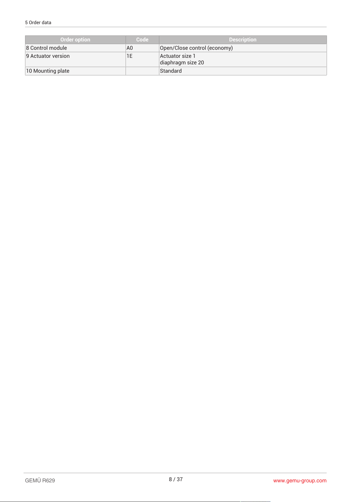
5 Order data ................................................................. 7
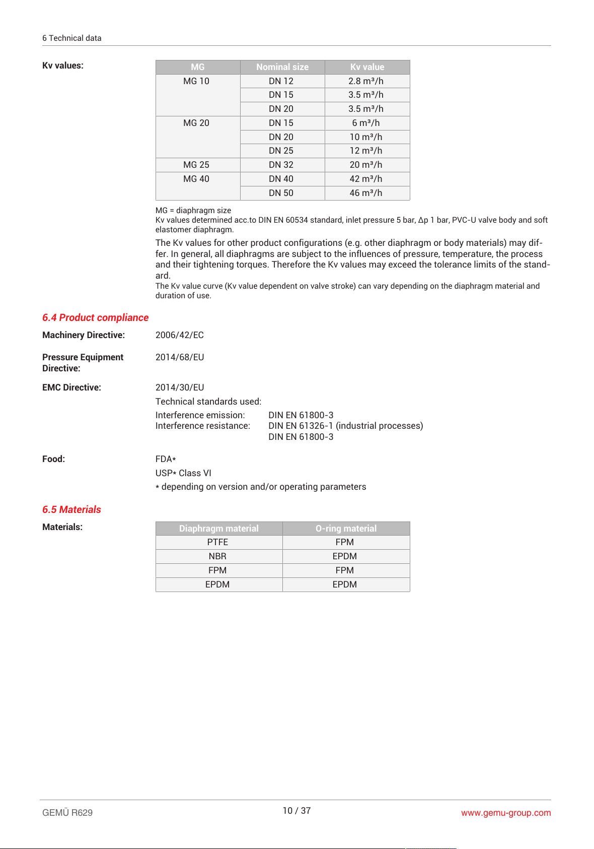
6 Technical data ........................................................... 9
6.7 Duty cycle and service life ................................. 11
7 Dimensions ............................................................... 13
7.1 Actuator dimensions .......................................... 13
7.2 Body dimensions ................................................ 14
7.3 Valve body mounting ......................................... 25
7.4 Mounting plate ................................................... 25
8 Manufacturer's information ....................................... 26
8.1 Delivery ............................................................... 26
8.2 Packaging ........................................................... 26
8.3 Transport ............................................................ 26
8.4 Storage ............................................................... 26
9 Installation in piping .................................................. 26
9.1 Preparing for installation ................................... 26
9.2 Installation position ........................................... 27
9.3 Installation with butt weld spigots .................... 27
9.4 Installation with threaded sockets .................... 27
9.5 Installation with threaded spigots .................... 27
9.6 Installation with union ends .............................. 28
9.7 Installation with solvent cement sockets ......... 28
9.8 Installation with flare connection ...................... 28
9.9 Installation with flanged connection ................. 28
10 Electrical connection ................................................. 29
10.1 Electrical connection of actuator ...................... 29
11 Operation .................................................................. 30
11.1 Manual override .................................................. 30
12 Inspection and maintenance ...................................... 30
14 Removal from piping ................................................. 34
15 Disposal .................................................................... 34
16 Returns ..................................................................... 34
17 Declaration of Incorporation according to 2006/42/
EC (Machinery Directive) ........................................... 35
18 Declaration of conformity according to 2014/30/EU
(EMC Directive) ......................................................... 36
GEMÜ R629www.gemu-group.com 3 / 37
All manuals and user guides at all-guides.com

www.gemu-group.com4 / 37GEMÜ R629
1 General information
1.1 Information
– The descriptions and instructions apply to the stand-
ard versions. For special versions not described in this
document the basic information contained herein ap-
plies in combination with any additional special docu-
mentation.
– Correct installation, operation, maintenance and repair
work ensure faultless operation of the product.
– Should there be any doubts or misunderstandings, the
German version is the authoritative document.
– Contact us at the address on the last page for staff
training information.
1.2 Symbols used
The following symbols are used in this document:
Symbol Meaning
Tasks to be performed
Response(s) to tasks
– Lists
1.3 Definition of terms
Working medium
The medium that flows through the GEMÜ product.
Diaphragm size
Uniform seat size of GEMÜ diaphragm valves for different
nominal sizes.
1.4 Warning notes
Wherever possible, warning notes are organised according to
the following scheme:
SIGNAL WORD
Type and source of the danger
Possible
symbol for the
specific
danger
Possible consequences of non-observance.
Measures for avoiding danger.
Warning notes are always marked with a signal word and
sometimes also with a symbol for the specific danger.
The following signal words and danger levels are used:
DANGER
Imminent danger!
▶Non-observance can cause death or
severe injury.
WARNING
Potentially dangerous situation!
▶Non-observance can cause death or
severe injury.
CAUTION
Potentially dangerous situation!
▶Non-observance can cause moderate
to light injury.
NOTICE
Potentially dangerous situation!
▶Non-observance can cause damage to
property.
The following symbols for the specific dangers can be used
within a warning note:
Symbol Meaning
Danger of explosion
Corrosive chemicals!
Hot plant components!
Damage to the product
All manuals and user guides at all-guides.com

www.gemu-group.com 5 / 37 GEMÜ R629
2 Safety information
The safety information in this document refers only to an in-
dividual product. Potentially dangerous conditions can arise
in combination with other plant components, which need to
be considered on the basis of a risk analysis. The operator is
responsible for the production of the risk analysis and for
compliance with the resulting precautionary measures and
regional safety regulations.
The document contains fundamental safety information that
must be observed during commissioning, operation and
maintenance. Non-compliance with these instructions may
cause:
– Personal hazard due to electrical, mechanical and
chemical effects.
– Hazard to nearby equipment.
– Failure of important functions.
– Hazard to the environment due to the leakage of dan-
gerous materials.
The safety information does not take into account:
– Unexpected incidents and events, which may occur
during installation, operation and maintenance.
– Local safety regulations which must be adhered to by
the operator and by any additional installation person-
nel.
Prior to commissioning:
1. Transport and store the product correctly.
2. Do not paint the bolts and plastic parts of the product.
3. Carry out installation and commissioning using trained
personnel.
4. Provide adequate training for installation and operating
personnel.
5. Ensure that the contents of the document have been fully
understood by the responsible personnel.
6. Define the areas of responsibility.
7. Observe the safety data sheets.
8. Observe the safety regulations for the media used.
During operation:
9. Keep this document available at the place of use.
10. Observe the safety information.
11. Operate the product in accordance with this document.
12. Operate the product in accordance with the specifica-
tions.
13. Maintain the product correctly.
14. Do not carry out any maintenance work and repairs not
described in this document without consulting the manu-
facturer first.
In cases of uncertainty:
15. Consult the nearest GEMÜ sales office.
3 Product description
3.1 Construction
12
3
4
5
6
Ite
m
Name Materials
1 Optical position indicator PA 12
2 Manual override
3 Motorized actuator Polyamide 50% glass fibre
4 Diaphragm EPDM, FKM, NBR, PTFE/
EPDM
5 Valve body Inliner PP-H, grey /
outliner PP, reinforced |
Inliner PP-H, natural /
outliner PP, reinforced |
Inliner PVDF / outliner PP,
reinforced | PVC-U, grey |
ABS | PP | PP, reinforced |
PP-H, natural | PVDF
6 Electrical connection
3.2 Description
The GEMÜ R629 eSyLite 2/2-way diaphragm valve is motor-
ized. It is available as an OPEN/CLOSE version. An integral
optical position indicator is standard.
3.3 Function
The product controls or regulates (depending on version) a
flowing medium by being closed or opened by a motorized
actuator.
The product has an optical position indicator as standard.
The optical position indicator indicates the OPEN and
CLOSED positions.
3 Product description
All manuals and user guides at all-guides.com

www.gemu-group.com6 / 37GEMÜ R629
4 Correct use
4 Correct use
DANGER
Danger of explosion
▶Risk of death or severe injury.
●Do not use the product in potentially
explosive zones.
WARNING
Improper use of the product
▶Risk of severe injury or death.
▶Manufacturer liability and guarantee will be void.
●Only use the product in accordance with the operating
conditions specified in the contract documentation and
in this document.
The product is designed for installation in piping systems
and for controlling a working medium.
The product is not intended for use in potentially explosive
areas.
●Use the product in accordance with the technical data.
All manuals and user guides at all-guides.com

5 Order data
Order codes
The order data provide an overview of standard configurations.
Please check the availability before ordering. Other configurations available on request.
1 Type Code
Diaphragm valve, motorized,
plastic diaphragm valve
R629
2 DN Code
DN 12 12
DN 15 15
DN 20 20
DN 25 25
DN 32 32
DN 40 40
DN 50 50
3 Body configuration Code
2/2-way body D
4 Connection type Code
Spigot DIN 0
Threaded socket DIN ISO 228 1
Solvent cement socket DIN 2
Flange EN 1092, PN 10, form B,
face-to-face dimension FTF EN 558 series 1, ISO
5752, basic series 1
4
Union end with DIN insert (socket) 7
Union end with Rp threaded socket insert 7R
Spigot for IR butt welding 20
Spigot for IR butt welding, BCF 28
Imperial butt weld spigot 30
Union end with inch insert - BS (socket) 33
Flange ANSI Class 125/150 RF,
face-to-face dimension FTF EN 558 series 1, ISO
5752, basic series 1,
length only for body configuration D
39
Union end with inch insert – ASTM (socket) 3M
Union end with JIS insert (socket) 3T
Flare connection with PVDF union nut 75
Union end with DIN insert (for IR butt welding) 78
5 Valve body material Code
PVC-U, grey 1
ABS 4
PP, reinforced 5
PVDF 20
Inliner PP-H, grey,
outliner PP, reinforced
71
Inliner PVDF/outliner PP, reinforced 75
PP-H, natural N5
6 Diaphragm material Code
NBR 2
FPM 4
EPDM 14
PTFE/EPDM one-piece 54
7 Voltage/Frequency Code
24 V DC C1
8 Control module Code
Open/Close control (economy) A0
Open/Close control (economy)
with emergency power supply module (NC)
A1
Open/Close control (economy)
with emergency power supply module (NO)
A2
9 Actuator version Code
Actuator size 1
diaphragm size 10
1C
Actuator size 1
diaphragm size 20
1E
Actuator size 1
diaphragm size 25
1F
Actuator size 3
diaphragm size 40
3H
10 Mounting plate Code
With mounting plate M
Without mounting plate O
Standard
Order example
Order option Code Description
1 Type R629 Diaphragm valve, motorized,
plastic diaphragm valve
2 DN 25 DN 25
3 Body configuration D 2/2-way body
4 Connection type 7 Union end with DIN insert (socket)
5 Valve body material 1 PVC-U, grey
6 Diaphragm material 14 EPDM
7 Voltage/Frequency C1 24 V DC
5 Order data
www.gemu-group.com 7 / 37 GEMÜ R629
All manuals and user guides at all-guides.com

Order option Code Description
8 Control module A0 Open/Close control (economy)
9 Actuator version 1E Actuator size 1
diaphragm size 20
10 Mounting plate Standard
5 Order data
www.gemu-group.com
8 / 37
GEMÜ R629
All manuals and user guides at all-guides.com

6 Technical data
6.1 Medium
Working medium: Corrosive, inert, gaseous and liquid media which have no negative impact on the physical and
chemical properties of the body and diaphragm material.
The valve will seal in both flow directions up to full operating pressure (gauge pressure).
6.2 Temperature
Media temperature: PVC-U, grey ABS PP, rein-
forced / PP-
H, natural
PVDF Inliner PP-H
grey / outliner
PP, reinforced
Inliner PVDF /
outliner PP,
reinforced
Code 1 Code 4 Code 5 / N5 Code 20 Code 71 Code 75
10 to 60 °C -10 to 60 °C 5 to 80 °C -10 to 80 °C 5 to 80 °C -10 to 80 °C
Ambient temperature: PVC-U, grey ABS PP, rein-
forced / PP-
H, natural
PVDF Inliner PP-H
grey / outliner
PP, reinforced
Inliner PVDF /
outliner PP,
reinforced
Code 1 Code 4 Code 5 / N5 Code 20 Code 71 Code 75
10 to 50 °C -10 to 50 °C 5 to 50 °C 0 to 50°C 5 to 50 °C -10 to 50 °C
If the emergency power module is used (control module code A1, A2), the maximum ambient tem-
perature is reduced to 40 °C.
6.3 Pressure
Operating pressure: 0 to 6 bar
All pressures are gauge pressures. Operating pressure values were determined with static operat-
ing pressure applied on one side of a closed valve. Sealing at the valve seat and atmospheric seal-
ing is ensured for the given values.
Information on operating pressures applied on both sides and for high purity media on request.
Pressure/temperature
correlation: Valve body material Temperature in °C (valve body)
MG Materials Code -1
0
±0 5 10 20 25 30 40 50 60 70 80
10 PVC-U 1 - - - 6.0 6.0 6.0 4.8 3.6 2.1 0.9 - -
PP 5 / N5 - - 6.0 6.0 6.0 6.0 5.1 4.2 3.3 2.4 1.6 0.9
PP-H 5 / N5 - - 6.0 6.0 6.0 6.0 5.1 4.2 3.3 2.4 1.6 0.9
PVDF 20 6.0 6.0 6.0 6.0 6.0 6.0 5.4 4.8 4.3 3.8 3.2 2.8
20,
25, 40
PVC-U 1 - - - 6.0 6.0 6.0 6.0 6.0 3.5 1.5 - -
ABS 4 6.0 6.0 6.0 6.0 6.0 6.0 6.0 6.0 4.0 2.0 - -
PP-H 71 - - 6.0 6.0 6.0 6.0 6.0 6.0 5.5 4.0 2.7 1.5
PVDF 75 6.0 6.0 6.0 6.0 6.0 6.0 6.0 6.0 6.0 6.0 5.4 4.7
Permissible operating pressure in bar
The pressure rating (PN) depends on the connection code.
Data for extended temperature ranges on request. Please note that the ambient temperature and media tem-
perature generate a combined temperature at the valve body which must not exceed the above values.
GEMÜ R629www.gemu-group.com 9 / 37
6 Technical data
All manuals and user guides at all-guides.com

Kv values: MG Nominal size Kv value
MG 10 DN 12 2.8 m³/h
DN 15 3.5 m³/h
DN 20 3.5 m³/h
MG 20 DN 15 6 m³/h
DN 20 10 m³/h
DN 25 12 m³/h
MG 25 DN 32 20 m³/h
MG 40 DN 40 42 m³/h
DN 50 46 m³/h
MG = diaphragm size
Kv values determined acc.to DIN EN 60534 standard, inlet pressure 5 bar, Δp 1 bar, PVC-U valve body and soft
elastomer diaphragm.
The Kv values for other product configurations (e.g. other diaphragm or body materials) may dif-
fer. In general, all diaphragms are subject to the influences of pressure, temperature, the process
and their tightening torques. Therefore the Kv values may exceed the tolerance limits of the stand-
ard.
The Kv value curve (Kv value dependent on valve stroke) can vary depending on the diaphragm material and
duration of use.
6.4 Product compliance
Machinery Directive: 2006/42/EC
Pressure Equipment
Directive:
2014/68/EU
EMC Directive: 2014/30/EU
Technical standards used:
Interference emission: DIN EN 61800-3
Interference resistance: DIN EN 61326-1 (industrial processes)
DIN EN 61800-3
Food: FDA*
USP* Class VI
* depending on version and/or operating parameters
6.5 Materials
Materials: Diaphragm material O-ring material
PTFE FPM
NBR EPDM
FPM FPM
EPDM EPDM
www.gemu-group.com
10 / 37
GEMÜ R629
6 Technical data
All manuals and user guides at all-guides.com

6.6 Mechanical data
Protection class: IP 65 acc. to EN 60529
Actuating speed: Max. 2 mm/s
Flow direction: Optional
Installation position: Optional
Weight: Actuator
Diaphragm size 10: 0.8 kg
MG 20: 0.88 kg
MG 25: 0.94 kg
MG 40: 1.4 kg
Body
Connection
types
code 1)
0, 30 20 28 7, 7R 33 3M,
3T
78 4, 39 1 75 2
MG DN
10 12 - - - - - - - - 0.08 - 0.06
15 - - 0.13 0.18 0.13 - - - - 0.08 -
20 ---------0.125-
20 15 0.12 0.10 - 0.17 0.24 0.26 0.27 0.67 - - -
20 0.13 0.12 - 0.21 0.28 0.30 0.36 0.84 - - -
25 0.16 0.14 - 0.26 0.33 0.38 0.37 1.28 - - -
25 32 0.22 0.18 - 0.40 0.70 0.73 0.63 1.89 - - -
40 40 0.50 0.40 - 0.73 0.83 0.93 1.13 2.36 - - -
50 0.57 0.47 - 1.00 1.40 1.50 1.60 3.08 - - -
Weights in kg
1) Connection type
Code 0: Spigot DIN
Code 1: Threaded socket DIN ISO 228
Code 2: Solvent cement socket DIN
Code 3M: Union end with inch insert – ASTM (socket)
Code 3T: Union end with JIS insert (socket)
Code 4: Flange EN 1092, PN 10, form B, face-to-face dimension FTF EN 558 series 1, ISO 5752, basic series
1
Code 7: Union end with DIN insert (socket)
Code 7R: Union end with Rp threaded socket insert
Code 20: Spigot for IR butt welding
Code 28: Spigot for IR butt welding, BCF
Code 30: Imperial butt weld spigot
Code 33: Union end with inch insert - BS (socket)
Code 39: Flange ANSI Class 125/150 RF, face-to-face dimension FTF EN 558 series 1, ISO 5752, basic
series 1, length only for body configuration D
Code 75: Flare connection with PVDF union nut
Code 78: Union end with DIN insert (for IR butt welding)
6.7 Duty cycle and service life
Service life: Class A acc. to EN 15714-2
Minimum 50,000 switching cycles at room temperature and permissible duty cycle.
Duty cycle: max. 30% duty
GEMÜ R629www.gemu-group.com 11 / 37
6 Technical data
All manuals and user guides at all-guides.com

6.8 Electrical data
Supply voltage: 24 V DC
Tolerance ± 10 %
Operating time: MG 10: 2.5 s
MG 20: 3.5 s
MG 25: 4.0 s
MG 40: 4.5 s
Close tight current / rated
current:
MG 10: 0.9 A
MG 20: 1.4 A
MG 25: 2.0 A
MG 40: 2.3 A
Starting current /
maximum current:
MG 10: approx. 2.8 A
MG 20: approx. 2.8 A
MG 25: approx. 2.8 A
MG 40: approx. 5.6 A
Standby current
consumption:
approx. 10 mA
6.8.1 Digital input signals
Input voltage: max. 30 V DC
High level: ≥ 18 V DC
Low level: ≤ 5 V DC
6.8.2 Emergency power supply module
Charging current: MG 10, MG 20, MG 25: max. 0.16 A
MG 40: 0.32 A
Charging time: approx. 13 min
Service life: Guide value at 25 °C ambient temperature, approx. 3 years
www.gemu-group.com
12 / 37
GEMÜ R629
6 Technical data
All manuals and user guides at all-guides.com

7 Dimensions
7.1 Actuator dimensions
B2
A
A1
B1
B3
B
MG A A1 B B1 B2 B3
10 192.0 63.0 59.5 134.5 115.0 82.0
20 195.0 66.0 59.5 134.5 115.0 82.0
25 204.0 75.0 59.5 134.5 115.0 82.0
40 228.0 91.0 80.0 167.0 147.5 94.5
Dimensions in mm
MG = diaphragm size
* CT = A + H1 (see body dimensions)
GEMÜ R629www.gemu-group.com 13 / 37
7 Dimensions
All manuals and user guides at all-guides.com

7.2 Body dimensions
7.2.1 Union end code 7
L1
H1
H
L2
R
ØD
Ød
Material code 1, 5, 20, N5
MG DN Connection type code 7 1)
Material Code 2)
1, 20 5, N5 1, 20 5, N5 1, 20 5, N5
R øD ød L1 L2 H H1
10 15 G1 43.0 20.0 90.0 128.0 125.0 30.0 41.0 15.0 16.0
Material code 4, 71, 75,
MG DN Connection type code 7 1)
Material code 2)
1 4 71 75
R øD L1 H H1 ød L2
20 15 G 1 43.0 108.0 36.0 10.0 20.0 146.0 150.0 143.0 146.0
20 G 1¼ 53.0 108.0 38.0 12.0 25.0 152.0 156.0 146.0 150.0
25 G 1½ 60.0 116.0 39.0 13.0 32.0 166.0 170.0 158.0 162.0
25 32 G 2 74.0 134.0 41.0 15.0 40.0 192.0 196.0 181.0 184.0
40 40 G 2¼ 83.0 154.0 63.2 23.2 50.0 222.0 222.0 207.0 210.0
50 G 2 3/4 103.0 184.0 63.2 23.2 63.0 266.0 266.0 245.0 248.0
Dimensions in mm
MG = diaphragm size
1) Connection type
Code 7: Union end with DIN insert (socket)
2) Valve body material
Code 1: PVC-U, grey
Code 4: ABS
Code 5: PP, reinforced
Code 20: PVDF
Code 71: Inliner PP-H, grey, outliner PP, reinforced
Code 75: Inliner PVDF/outliner PP, reinforced
Code N5: PP-H, natural
www.gemu-group.com
14 / 37
GEMÜ R629
7 Dimensions
All manuals and user guides at all-guides.com

7.2.2 Union end code 7R
Rp
L2
L1
H
R
H1
ØD
MG DN Connection type code 7R 1)
Material code 1 2)
R øD L1 H H1 L2 Rp
20 15 G 1 43.0 108.0 36.0 10.0 146.0 1/2
20 G 1¼ 53.0 108.0 38.0 12.0 152.0 3/4
25 G 1½ 60.0 116.0 39.0 13.0 166.0 1
25 32 G 2 74.0 134.0 41.0 15.0 192.0 1¼
40 40 G 2¼ 83.0 154.0 63.2 23.2 222.0 1½
50 G 2 3/4 103.0 184.0 63.2 23.2 266.0 2
Dimensions in mm
MG = diaphragm size
1) Connection type
Code 7R: Union end with Rp threaded socket insert
2) Valve body material
Code 1: PVC-U, grey
GEMÜ R629www.gemu-group.com 15 / 37
7 Dimensions
All manuals and user guides at all-guides.com

7.2.3 Union end code 33, 3M
L1
H1
H
L2
R
ØD
Ød
MG DN Connection types code 1)
33, 3M 33 33 33 3M 3M
Material code 2)
1, 4 1 4 1, 4 1 1, 4
NPS R øD L1 H H1 L2 L2 ød L2 ød
10 15 1/2'' G1 43.0 90.0 30.0 15.0 128.0 - 21.4 - -
20 15 1/2" G 1 43.0 108.0 36.0 10.0 146.0 150.0 21.4 158.0 21.4
20 3/4" G 1¼ 53.0 108.0 38.0 12.0 152.0 156.0 26.8 164.0 26.7
25 1" G 1½ 60.0 116.0 39.0 13.0 166.0 170.0 33.6 180.0 33.5
25 32 1¼" G 2 74.0 134.0 41.0 15.0 192.0 198.0 42.3 204.0 42.2
40 40 1½" G 2¼ 83.0 154.0 63.2 23.2 222.0 220.0 48.3 230.0 48.3
50 2" G 2 3/4 103.0 184.0 63.2 23.2 264.0 264.0 60.4 266.0 60.4
Dimensions in mm
MG = diaphragm size
1) Connection type
Code 33: Union end with inch insert - BS (socket)
Code 3M: Union end with inch insert – ASTM (socket)
2) Valve body material
Code 1: PVC-U, grey
Code 4: ABS
www.gemu-group.com
16 / 37
GEMÜ R629
7 Dimensions
All manuals and user guides at all-guides.com

7.2.4 Union end code 3T
L1
H1
H
L2
R
ØD
Ød
MG DN Connection type code 3T 1)
Material code 1 2)
R øD L1 H H1 L2 ød
20 15 G 1 43.0 108.0 36.0 10.0 152.0 22.0
20 G 1¼ 53.0 108.0 38.0 12.0 152.0 26.0
25 G 1½ 60.0 116.0 39.0 13.0 166.0 32.0
25 32 G 2 74.0 134.0 41.0 15.0 192.0 38.0
40 40 G 2¼ 83.0 154.0 63.2 23.2 222.0 48.0
50 G 2 3/4 103.0 184.0 63.2 23.2 266.0 60.0
Dimensions in mm
MG = diaphragm size
1) Connection type
Code 3T: Union end with JIS insert (socket)
2) Valve body material
Code 1: PVC-U, grey
GEMÜ R629www.gemu-group.com 17 / 37
7 Dimensions
All manuals and user guides at all-guides.com

7.2.5 Union end code 78
ØD
Ød
L2
H
H1
R
L1
S
C
Material code 5, 20, N5
MG DN Connection type code 78 1)
Material code
5 20, N5 5 20, N5
R L1 L2 øD ød s c H H1
10 15 1 90.0 196.0 42.0 20.0 1.9 36.0 30.0 41.0 15.0 16.0
Material code 71, 75
MG DN Connection type code 78 1)
Material code 2)
71 75
L1 L2 H H1 øD ød R s c
20 15 108.0 214.0 36.0 10.0 43.0 20.0 G 1 1.9 1.9 36.0
20 108.0 220.0 38.0 12.0 53.0 25.0 G 1¼ 2.3 1.9 37.0
25 116.0 234.0 39.0 13.0 60.0 32.0 G 1½ 2.9 2.4 39.0
25 32 134.0 258.0 41.0 15.0 74.0 40.0 G 2 3.7 2.4 39.0
40 40 154.0 284.0 63.2 23.2 83.0 50.0 G 2¼ 4.6 3.0 43.0
50 184.0 320.0 63.2 23.2 103.0 63.0 G 2 3/4 5.8 3.0 43.0
Dimensions in mm
MG = diaphragm size
1) Connection type
Code 78: Union end with DIN insert (for IR butt welding)
2) Valve body material
Code 20: PVDF
Code 5: PP, reinforced
Code 71: Inliner PP-H, grey, outliner PP, reinforced
Code 75: Inliner PVDF/outliner PP, reinforced
Code N5: PP-H, natural
www.gemu-group.com
18 / 37
GEMÜ R629
7 Dimensions
All manuals and user guides at all-guides.com

7.2.6 Spigot code 0, 30
L
c
Ød
H1
H
MG DN Connection types code 1)
0 30
Material code 2)
1 71, 75 1 71, 75 1, 4
NPS L H H H1 ød c c L H H1 ød c
20 15 1/2" 124.0 36.0 36.0 10.0 20.0 16.0 18.0 141.0 36.0 10.0 21.4 24.0
20 3/4" 144.0 38.0 38.0 12.0 25.0 19.0 19.0 144.0 38.0 12.0 26.7 27.0
25 1" 154.0 39.0 39.0 13.0 32.0 22.0 22.0 154.0 39.0 13.0 33.6 30.0
25 32 1¼" 174.0 41.0 41.0 15.0 40.0 32.0 32.0 174.0 41.0 15.0 42.2 33.0
40 40 1½" 194.0 63.2 63.2 23.2 50.0 35.0 26.0 194.0 63.2 23.2 48.3 35.0
50 2" 224.0 63.2 63.2 23.2 63.0 38.0 33.0 224.0 63.2 23.2 60.3 40.0
Dimensions in mm
MG = diaphragm size
1) Connection type
Code 0: Spigot DIN
Code 30: Imperial butt weld spigot
2) Valve body material
Code 1: PVC-U, grey
Code 20: PVDF
Code 4: ABS
Code 5: PP, reinforced
Code 71: Inliner PP-H, grey, outliner PP, reinforced
Code 75: Inliner PVDF/outliner PP, reinforced
GEMÜ R629www.gemu-group.com 19 / 37
7 Dimensions
All manuals and user guides at all-guides.com

7.2.7 Spigot code 20, 28
L
c
Ød
H1
H
s
MG DN Connection types code 1) 20, 28
Material code 2)
20 71 75
NPS L H H1 ød c s
10 15 134 41 16 20 31 1.9 - -
20 15 1/2" 154.0 36.0 10.0 20.0 33.0 - 1.9 1.9
20 3/4" 154.0 38.0 12.0 25.0 33.0 - 2.3 1.9
25 1" 154.0 39.0 13.0 32.0 33.0 - 2.9 2.4
25 32 1¼" 194.0 41.0 15.0 40.0 33.0 - 3.7 2.4
40 40 1½" 194.0 63.2 23.2 50.0 33.0 - 4.6 3.0
50 2" 224.0 63.2 23.2 63.0 33.0 - 5.8 3.0
Dimensions in mm
MG = diaphragm size
1) Connection type
Code 20: Spigot for IR butt welding
Code 28: Spigot for IR butt welding, BCF
2) Valve body material
Code 20: PVDF
Code 71: Inliner PP-H, grey, outliner PP, reinforced
Code 75: Inliner PVDF/outliner PP, reinforced
www.gemu-group.com
20 / 37
GEMÜ R629
7 Dimensions
All manuals and user guides at all-guides.com
Table of contents
Other Gemu Control Unit manuals
Popular Control Unit manuals by other brands

Eaton
Eaton MMX-COM-PC Instruction leaflet

Bosch
Bosch IOS 0232 A installation manual

Agilent Technologies
Agilent Technologies G4239C instructions

Panasonic
Panasonic SF-C21 instruction manual

HYDAC FILTER SYSTEMS
HYDAC FILTER SYSTEMS CTM-EB 1000 Series Operating and maintenance instructions

Inovance
Inovance GL20-0016ETN user guide

ProSoft Technology
ProSoft Technology ILX800-SMSG user manual

NI
NI 9477 Getting started guide

Viessmann
Viessmann EM-EA1 extension Installation and service instructions

Allen-Bradley
Allen-Bradley 1794-IA8 installation guide

IBM
IBM MegaBasic IC697PCM711 quick start guide

phytron
phytron TM StepDrive 1x24..48V/5A manual