GF 3-2630-X User manual

The GF Amperometric Chlorine Electrodes is designed for use in fresh,
clean water treatment applications where a level of Chlorine is always detectable.
Free Chlorine electrodes are available in measurement ranges of 0.02 to 2 ppm,
0.05 to 5 ppm or 0.1 to 20 ppm.
Chlorine Dioxide electrodes are available in measurement ranges of 0.02 to 2 ppm.
Electrodes require the 2650 Amperometric Electronics to output a digital (S
3
L) signal to
the 9950-3 Chlorine Controller.
Features:
• Utilizing smart-sensor technology, this electrode incorporates a unique
embedded memory chip within the electrode to communicate a wide variety
of information to the 2650 Amperometric Electronics and
9950-3 Chlorine
Controller
. Electrode type, factory calibration data, service time, chlorine range,
high and low temperature and more are stored on the chip. This information is
accessible via the
9950-3 Chlorine Controller
.
• GF's patented DryLoc®connector provides quick assembly and a secure
connection. Gold-plated contacts and an O-ring seal ensure a waterproof and
reliable interconnect to the 2650 Amperometric Electronics.
• Integrated temperature element for automatic temperature compensation.
• Separate drive electronics (2650) allow easy electrode replacement without
running new cable.
English
*3-2630.090*
3-2630.090 Rev 15 02/21
GF 3-2630-X Amperometric Free Chlorine Electrode
GF 3-2632-X Amperometric Chlorine Dioxide Electrode
Manual
CAUTION!
1. Follow instructions carefully to avoid personal injury or damage to electrode.
2. Prior to installation or removal:
a. Disconnect flow through system.
b. Drain below sensor level.
3. Confirm chemical compatibility before use.
4. Do not exceed the maximum pressure or temperature specifications.
5. Do not alter product construction.
Description
• English
• Deutsch
• Français
• Español
• Italiano
• 中文
WARNING: The GF Chlorine Analyzer (electrode) is designed to be used in a
clean, chlorinated flowing stream at all times. DO NOT use in applications where
electrode could be exposed to periods without chlorine.

2GF 263X Series Chlorine Electrodes
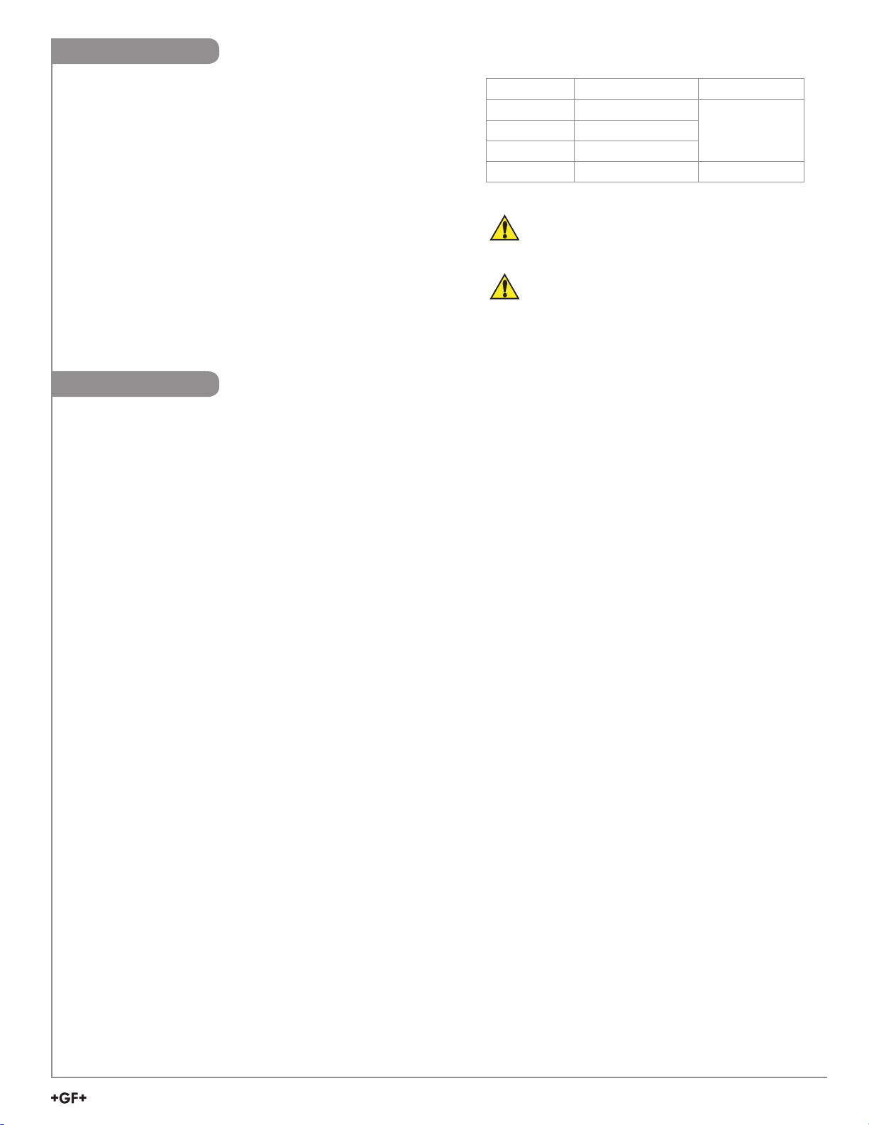
Dimensions
Warranty Information
Safety Information
Refer to your local Georg Fischer Sales office for the most
current warranty statement.
All warranty and non-warranty repairs being returned must
include a fully completed Service Form and goods must be
returned to your local GF Sales office or distributor.
Product returned without a Service Form may not be
warranty replaced or repaired.
GF products with limited shelf-life (e.g. pH, ORP, chlorine
electrodes, calibration solutions; e.g. pH buffers, turbidity
standards or other solutions) are warranted out of box but not
warranted against any damage, due to process or application
failures (e.g. high temperature,
chemical poisoning, dry-out)
or mishandling (e.g. broken glass,
damaged membrane,
freezing and/or extreme temperatures).
Caution / Warning / Danger
Indicates a potential hazard. Failure to follow all warnings
may lead to equipment damage, injury, or death.
Electrocution Danger
Alerts user to risk of
potential of injury or death via
electrocution.
Electrostatic Discharge (ESD)
Alerts user to risk of potential damage to product by ESD.
Personal Protective Equipment (PPE)
Always utilize the most appropriate PPE during
installation and service of GF products.
Pressurized System Warning
Sensor may be under pressure, take caution to vent
system prior to installation or removal. Failure to do so
may result in equipment damage and/or serious injury.
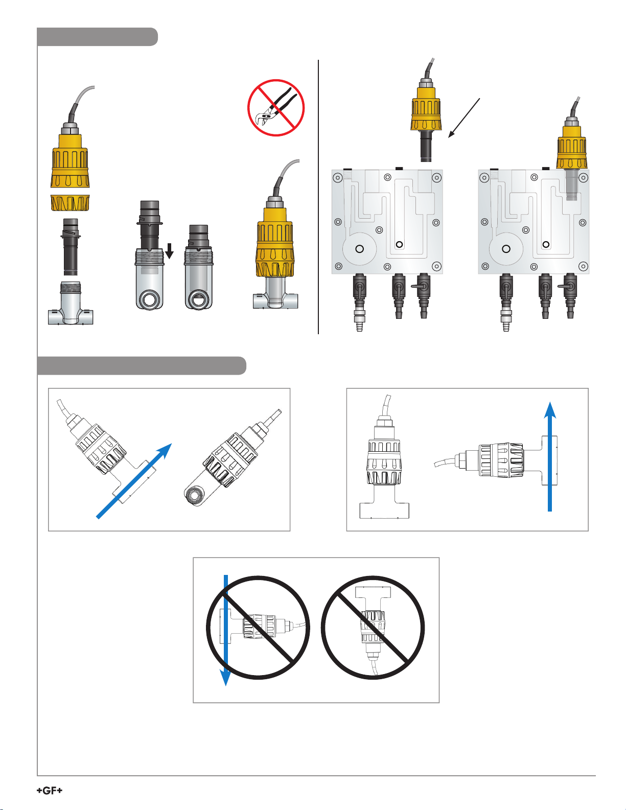
Hand Tighten Only
Overtightening may permanently damage product threads
and lead to failure of the retaining nut.
Do Not Use Tools
Use of tool(s) may damage product beyond repair and
potentially void product warranty.
Note / Technical Notes
Highlights additional information or detailed procedure.
DO NOT
FREEZE
Do Not Freeze
Products are temperature sensitive and may contain
freezable liquids. Freezing damage to pH, ORP, and
Chlorine electrodes voids product warranty.
74.4 mm (2.93 in.)
25.15 mm (.99 in.)
109.2 mm (4.3 in.)
26.4 mm (1.04 in.)
Description ............................................................................... 1
Warranty Information................................................................ 2
Safety Information .................................................................... 2
Dimensions .............................................................................. 2
Specifications ........................................................................... 3
Sensor Preparation .................................................................. 4
Operation ................................................................................. 5
Calibration ................................................................................ 5
Maintenance............................................................................. 6
Storage .................................................................................... 7
Reconditioning ......................................................................... 8
Installation ................................................................................ 9
Mounting Position .................................................................... 9
Overview ................................................................................ 10
Troubleshooting ......................................................................11
Ordering Information .............................................................. 12
Table of Contents

3
GF 263X Series Chlorine Electrodes
Operational Ranges and Limits
Free Chlorine
Range
3-2630-1.........................
0.02 to 2 ppm (mg/L)
3-2630-2.........................
0.05 to 5 ppm (mg/L)
3-2630-3.........................
0.01 to 20 ppm (mg/L)
pH Operating Range..........5.5 pH to 8.2 pH
Chlorine Dioxide
Range
3-2632-1.........................
0.02 to 2 ppm (mg/L)
pH Operating Range..........4.0 pH to 11 pH
Maximum Operating
Temperature ......................5 °C to 45 °C (41 °F to 113 °F)
Maximum Operating
Pressure ............................0.48 bar @ 25 °C (7 psi @ 77 °F)
Flow Velocity Across Membrane Surface
Minimum ........................
15 cm/s (0.49 ft/s)
Maximum .......................
30 cm/s (0.98 ft/s)
Sensitivity
Free Chlorine
Cross Sensitivity ............Chlorine Dioxide, ozone, bromine
Chlorine Dioxide
Cross Sensitivity ............Free Chlorine, ozone
Chemical Compatibility......< 50% ethanol/water
< 50% glycerol/water
Environmental Requirements
Storage Temperature
(Dry).................................-10 °C to 60 °C (14 °F to 140 °F)
System Temperature......
-10 °C to 60 °C (14 °F to 140 °F)
Relative Humidity...........
0 to 95% indoor/outdoor
non-condensing to rated ambient
Standards and Approvals
• CE, WEEE
• RoHS Compliant
• Manufactured under ISO 9001 for quality
China RoHS (Go to www.gfsignet.com for details)
Declaration of Conformity according to FCC Part 15
This device complies with Part 15 of the FCC rules.
Operation is subject to the following two conditions:
(1) This device may not cause harmful interference, and
(2) This device must accept any interference received,
including interference that may cause undesired operation.
Specifications
General
Polarization Source....GF 2650 Amperometric Electronics
Compatible Flow
Cells ...........................GF 3-3610-1 (159 001 683)
GF 3-3610-2 (159 001 684)
GF 3-4630.392 (159 001 690)
Mounting.....................GF DryLoc connection
Materials.....................CPVC
Membrane ..................PTFE
O-ring..........................FKM
Working electrode.......Gold
Counter reference
electrode.....................Silver halide
Wetted Materials.........PVC, PTFE, FKM, Nylon, Silicone
Performance Specifications
Electrode
Repeatability ..............±0.08 ppm (mg/L) or 3% of selected
range, whichever is less
Free Chlorine Slope ...15 to 60 nA/ppm (mg/L) @ 25 °C
Chlorine Dioxide
Slope..........................40 to 200 nA/ppm (mg/L) @ 17 °C
Response Time, T90 ..< 2 minutes
System (including electronics and instrument)
Accuracy ....................<±3% of electrode signal after
calibration
Resolution ..................<0.5% of electrode range
Sensor Conditioning
New, first start up .......4 hours maximum before calibration
Subsequent
start ups .....................2 hours maximum
Temperature
Element....................... Pt1000

4GF 263X Series Chlorine Electrodes
Sensor Preparation
• Chlorine sensors are shipped without internal electrolyte solution.
• Prior to installation and supplying power, Chlorine sensors must be filled with the appropriate internal electrolyte solution.
• Verify the correct electrolyte solution is utilized with the corresponding sensor.
• Free Chlorine and Chlorine Dioxide sensors require different electrolyte solutions.
Avoid skin or eye contact with electrolyte solution.
Wear rubber gloves and goggles.
*Safety Data Sheets (SDS) are available online at www.gfsignet.com.
CAUTION! DO NOT touch the gold tip or the membrane of the sensor.
Initial Fill Procedure:
When adding electrolyte, be prepared for an accidental spill.
Working near a sink is recommended.
1. Remove the protective bottle from the end of the electrode.
2. Remove the membrane cap from the front of the sensor.
Note: When new sensors are shipped, the membrane cap is not tightened to
the sensor.
3. Fill supplied syringe with electrolyte solution.
4. Place the electrode on a level surface.
5. Insert syringe needle fully into one of the eight electrode holes while injecting
with electrolyte solution. Slowly injecting the electrolyte solution into the sensor
to avoid introducing air bubbles. The electrode holds approximately 14
milliliters of solution. Slowly fill until solution begins to flow out of holes. Do not
allow the solution to run down the electrode and wet the electrical contacts in
the DryLoc connector.
6. Slowly screw on the membrane cap finger tight. Do not use tools.
To avoid damage and contamination, do not touch the white membrane
surface on the membrane cap.
1
2
3
4
5
6
7
8
9
10
ml

5
GF 263X Series Chlorine Electrodes
Operation
Electrode Range: The electrode must match the type and range of
chlorine concentration to be measured.
Flow Rate:
The electrode must have a stable and constant flow of water past its
membrane for accurate measurement. When the sensor is installed
in the Tee flow cell (see Ordering Information), the flow rate must range
from 37.8 to 75.7 LPH (10 to 20 US g/h).
When the sensor is installed in the Flow Cell Block
3-4630.392 (159 001 690), the flow rate range should be
30.24 to 45.36 LPH (8 to 12 US gph).
Sensor Conditioning: 4 hours
A new electrode requires conditioning of 4 hours with the electrode
powered on and chlorinated water flowing past the sensor tip to
generate a stable reading.
Subsequent start-ups can require an electrode conditioning of up to two hours.
The maximum allowable operating pressure
must be less than 0.48 bar (7 psi).
Higher pressures will damage the electrode.
The electrode should not be used in water
containing surfactants, oils, organic chlorine
or stabilizers such as cyanuric acid.
Part Number Chlorine Range Chlorine Type
3-2630-1 0.02 to 2 ppm (mg/L)
Free Chlorine3-2630-2 0.05 to 5 ppm (mg/L)
3-2630-3 0.1 to 20 ppm (mg/L)
3-2632-1 0.02 to 2 ppm (mg/L) Chlorine Dioxide
Calibration
A new chlorine electrode or one that has had the membrane cap changed must be calibrated. Refer to the 463X Analyzer System
or 9950-3 Chlorine Controller manuals for electrode and instrument calibration information. A diethyl-p-phenylenediamine (DPD)
colorimeter test kit (not included) is required for sensor calibration. A sample is taken and analyzed with the DPD test kit, then this
value is entered into the Signet 9950-3 Chlorine Controller.
• Calibrate after a membrane cap change.
• Check calibration one day after sensor is placed in service.
• Check calibration weekly to monthly depending on process requirements.

6GF 263X Series Chlorine Electrodes
Maintenance
Verifying the sensor's accuracy using the DPD method should be performed to determine if the sensor requires maintenance.
1. Inspect the membrane for dirt or damage. Replace the membrane if it's torn or if the gold cathode is visible.
2. If the membrane is dirty clean the membrane by soaking it in 1 - 5% HCL and gently wash with a stream of DI water.
(do not use any mechanical device on the membrane)
Refill Procedure:
When adding electrolyte, be prepared for an accidental spill.
Working near a sink is recommended.
1. Remove the membrane cap from the front of the sensor.
2. Turn the sensor upside down and shake the sensor vigorously to remove
the internal electrolyte.
3. Fill supplied syringe with electrolyte solution.
4. Place the electrode on a level surface.
5.
Insert syringe needle fully into one of the eight electrode holes while
injecting with electrolyte solution. Slowly injecting the electrolyte solution
into the sensor to avoid introducing air bubbles. The electrode holds
approximately 14 milliliters of solution. Slowly fill until solution begins to
flow out of holes. Do not allow the solution to run down the electrode and
wet the electrical contacts in the DryLoc connector.
6. Slowly screw on the membrane cap finger tight. Do not use tools.
To avoid damage and contamination, do not touch the white membrane
surface on the membrane cap.
Avoid skin or eye contact with electrolyte solution.
Wear rubber gloves and goggles.
*Safety Data Sheets (SDS) are available online at www.gfsignet.com.
Additional caution should be taken when handling the Chlorine Dioxide electrolyte solution.
If a fresh water rinse does not clean the membrane, it will need to be replaced.
Keep spare membrane caps available. Membrane caps carry no warranty.
Diluted HCl can irritate the eyes and skin, use proper safety equipment.
Do not use surface tension reducing chemicals, detergents or solvents on the membrane.
1
2
3
4
5
6
7
8
9
10
ml

7
GF 263X Series Chlorine Electrodes
Storage
Dry electrodes are shipped and need to be stored between –10 ºC to 60 ºC (14 ºF to 140 ºF) at a relative humidity that
does not exceed 95%.The primary concerns when storing the electrode is damage to the membrane.
DO NOT
FREEZE
If the sensor or panel assembly is to be removed from service for a period of time the sensor must be properly prepared for storage
and may need to be recommissioned.
Storage periods of 1 week or less:
• Close the drain valve, then close the inlet valve of the flow cell, to maintain water inside the flow cell to keep the membrane wet.
• If draining the flow cell is required, remove the sensor from the cell and the 2650 electronics and store in the shipping bottle with
tap water added.
Storage periods more than 1 week:
• Remove the membrane cap and internal electrolyte solution.
• Rinse the sensor internal chamber with DI water or cold tap water; drain and allow to dry.
• Place the membrane cap back onto the sensor. INSTALL LOOSE, DO NOT COMPLETELY TIGHTEN THE CAP.
WHEN STORED DRY, THE MEMBRANE CAP MUST BE STORED RELAXED AND UNSTRESSED.
• Store sensor DRY in the shipping bottle, DO NOT ADD WATER.
Recommissioning Procedure:
1. Fill the sensor with the electrolyte as outlined in Maintenance, see page 6, and install the membrane cap.
2. The sensor will have to be polarized in the flow cell with flowing Chlorinated water before being used.
Note: This may take 30 to 120 minutes before calibration can be performed.
3. If the sensor does not recover after recommission, follow steps 1-10 outlined in Reconditioning on page 8.
4. If the sensor still fails to work properly, continue with steps 11-17.

8GF 263X Series Chlorine Electrodes
Reconditioning
Required to recondition a sensor:
• DI Water
• Beaker (any size available)
• Polishing Sheets (Included in sensor maintenance kit)
• Free Chlorine: Chlorine Bleach (13% concentration)
• Chlorine Dioxide: Aqueous Chlorine Dioxide solution
Reconditioning Procedure (Steps 1-10):
1. Remove the sensor from the 2650 electronics.
2. Remove the membrane cap.
3. Place the sensor on a firm, flat surface with gold
cathode pointing upward.
4. Apply a small amount of water to the blue (coarse)
polishing paper (dull side).
5. Polish the gold electrode by moving the paper in a
circular pattern for 30 seconds. DO NOT go back and
forth in a single direction. See Figure 1.
6. Rinse the sensor tip with DI water.
7. Apply a small amount of DI water to the white (fine)
polishing paper (dull side) and polish the gold
electrode by moving the paper in a circular pattern for
30 seconds. DO NOT go back and forth in a single
direction. See Figure 1.
8. Rinse the sensor tip with DI water.
9. Top off the sensor with electrolyte and inspect
membrane for dirt or damage. Replace if necessary.
10. Insert the sensor into the 2650-7 electronics and
apply power.
Reconditioning Procedure (Steps 11-17):
11. Fill beaker with a 12 mm (½ inch) of the appropriate
solution.
12. Position or suspend the sensor 6 mm to 12 mm
(¼ in. to ½ in.) above the appropriate solution. DO
NOT SUBMERGE THE SENSOR. See Figure 2.
13. Apply power to the system.
14. Monitor the nA of the sensor (press the down arrow
three times on the 9950-3 Chlorine Controller).
The nA reading should start to rise. Response time
and nA reading will depend upon the temperature of
the bleach.
15. Once the sensor's nA reading reaches approximately
300-360 nA, allow the sensor to remain in the beaker,
suspended over the appropriate solution, for an
additional 20 minutes.
• If sensor does not recover, cover the
beaker to avoid air contamination.
• Contact the factory for assistance
(www.gfsignet.com)
16. After 20 minutes, remove the sensor from the beaker
and install it into the flow cell and restore flow to the
system.
17. Calibrate the sensor after the system has become
stable.
CAUTION!
Bleach
and Chlorine Dioxide solutions are
very corrosive and
may release dangerous gases if they come in contact with
acids.
• Wear proper protective clothing (gloves and eye protection)
• Avoid contact with skin and eyes
• Observe all warnings on safety data sheets
• Avoid spilling bleach and possible contact with acids
Curved Surface
Figure 1
Figure 2
The electrode is not recyclable. Dispose of properly according to local, state and federal guidelines.

9
GF 263X Series Chlorine Electrodes
IN
OUT
pH Cl
IN
OUT
pH Cl
Installation
Lubricate O-rings with a
non-petroleum based,
viscous lubricant (grease)
compatible with the system.
Align tab on electrode with
notch on fitting. Insert until
fully seated.
Do Not Use Lubricant or Sealing Tape on Threads.
Do Not Overtighten. Do Not Use Tools.
pipe tee
When using the chlorine
panel flow cell it is not
necessary to lubricate
this O-ring.
Mounting Position - PVC Tee
Best
Flow Direction
Good
45º or or45º
Mount the flow cell where the sensor will be easily accessible.
To avoid air bubble entrapment, do not mount with downward flow.
NO
Flow

10 GF 263X Series Chlorine Electrodes
Overview
pH Compensation for Free Chlorine
Amperometric free chlorine sensors measure only hypochlorous
acid. As noted in the text above and in Figure 3, the ratio of
hypochlorous acid and hypochlorite is pH dependent.
The GF Free Chlorine Panel assemblies comes complete with
a pH electrode to ensure accurate free chlorine measurement if
the pH changes.
5.0 5.5 6.0 6.5 7.0 7.5 8.0 8.5 9.0 9.5 10.0
100
90
80
70
60
50
40
30
20
10
0
HOCl
OClØ
% free chlorine
pH at 25 °C
Chlorine Measurement by Amperometric Sensors
GF chlorine sensors are membrane-covered amperometric 2-electrode sensors. A gold or platinum cathode acts as the working
electrode with a silver halide acting as the counter electrode. Depending on the species to be analyzed, a polarization voltage is
applied between the two electrodes. When placed into service, the chlorine species of interest diffuses across the membrane and
is reduced at the cathode surface. For the case of total chlorine, the analyte reacts with the fill solution to produce an intermediate,
which is subsequently reduced at the cathode surface. At the same time, the silver anode is oxidized to form a silver halide. The
current generated at the cathode is proportional to the rate of diffusion through the membrane and the concentration of chlorine in the
sample. The current from the cathode to the anode is conditioned, digitized and transmitted by the associated electronics.
Chlorine in Water
Various forms of chlorine are used to disinfect water. Each form of chlorine has benefits and limitations which help determine the
specific application. The predominant categories used in disinfection are Free Chlorine, Total Chlorine and Chlorine Dioxide. Free
Chlorine is the sum of chlorine gas (Cl2), hypochlorous acid (HOCl) and hypochlorite (OCl
-
). Above pH 4.0 all of the molecular
chlorine is converted to HOCl and OCl
-
. Hypochlorous acid is a more potent disinfectant than hypochlorite and exists in a pH
dependent equilibrium as shown in Figure 3.
Free chlorine also combines with naturally occurring or human-introduced nitrogen compounds in the water to form chloramines, also
known as combined chlorine. Treatment operators introduce ammonia into the water to form monochloramine (NH2Cl), dichloramine
(NHCl2) and trichloramine (NCl3). Chloramines are a less effective disinfectant but have a longer residence time than the free chlorine
species. Total chlorine is the sum of free chlorine (Cl2, HOCl and OCl
-
) and combined chlorine (NH2Cl, NHCl2, NCl3).
Automatic pH Compensation and Free Chlorine
In many applications, the process pH does not significantly
fluctuate and only a chlorine sensor and instrument are
necessary for accurate chlorine measurement.
When the pH varies the free chlorine concentration cannot
accurately determined without the use of automatic pH
compensation.
The addition of the 3-2724-00 (159 001 545) pH electrode along
with its 3-2751-7 (159 001 957) sensor electronics to the system
makes pH compensation extremely easy and automatic even
with wide fluctuations or high pH.
See Figure 4 for pH variation recommendations.
Chlorine dioxide is not pH dependant and does not require a pH
electrode or electronics.
6.5 7.0 7.5 8.0 8.5 9.0
0
±0.3
±0.1
±0.2
=
pH variation
Sample pH
Automatic pH compensation recommended
in ranges within shaded area
Figure 3
Figure 4

11
GF 263X Series Chlorine Electrodes
Troubleshooting
Problem Possible Causes Remedies
Sensor cannot be calibrated.
Output is higher than DPD test
(out of range).
Sensor conditioning time too short Condition for 4 hours minimum prior to initial
calibration
Interference from contaminants See Specifications on page 3
Membrane cap damaged Replace cap and recondition
DPD chemicals bad Use fresh reagents
pH outside of working range See Specifications on page 3
Sensor cannot be calibrated.
Output is lower than DPD test.
Sensor conditioning time too short Condition for 4 hours minimum prior to initial
calibration
Chlorine content too low DPD value must be greater than 0.5 ppm to
calibrate
Low flow rate Check to make sure flow rate is sufficient
Air bubbles on electrode membrane Inspect visually. Tap to remove bubbles. Mount
at an angle.
Low or no electrolyte in electrode Fill electrode with electrolyte
Organic chlorination agents present in water See technical data
Surfactants in water Remove surfactants and replace cap
Membrane cap coated Clean or replace membrane cap
Membrane cap loose Tighten or replace membrane cap
pH outside working range. See Specifications on page 3
Sensor output very low
Sensor conditioning time too short Condition for 4 hours minimum prior to initial
calibration
Chlorine content too low Add chlorine to validate
Only bound chlorine present. No free chlorine Check for chloramine with appropriate DPD test
Electrode not making good contact with electronics Inspect and reconnect
Unstable output from sensor
Air bubbles on electrode membrane Inspect visually. Tap to remove bubbles. Mount
at an angle.
Membrane damaged Replace membrane. Condition sensor for at
least 2 hours and recalibrate.
Electrode not making good contact with electronics Inspect and reconnect
Non-sensor problem
Check 3-2650 Electronics connection to
electrode (see 3-2650 manual for instructions).
Make sure connections are dry. Check
instrument hookup.
Transmitter error messages related to calibration are detailed in the 9950-3 Chlorine Controller operation manual.

Georg Fischer Signet LLC, 3401 Aero Jet Avenue, El Monte, CA 91731-2882 U.S.A. • Tel. (626) 571-2770 • Fax (626) 573-2057
For Worldwide Sales and Service, visit our website: www.gfsignet.com • Or call (in the U.S.): (800) 854-4090
For the most up-to-date information, please refer to our website at www.gfsignet.com
3-2630.090 Rev 15 02/21 English © Georg Fischer Signet LLC 2021
Ordering Information
Mfr. Part No. Code Description
3-2630-1 159 001 746 Free Chlorine electrode, 0.02 to 2 ppm (mg/L)
3-2630-2 159 001 662 Free Chlorine electrode, 0.05 to 5 ppm (mg/L)
3-2630-3 159 001 747 Free Chlorine electrode, 0.1 to 20 ppm (mg/L)
3-2632-1 159 001 767 Chlorine Dioxide electrode, 0.02 to 2 ppm (mg/L)
Accessories and Replacement Parts
Mfr. Part No. Code Description
3-2630.391 159 001 674 Free Chlorine electrolyte, 30 mL
3-2632.391 159 310 160 Chlorine Dioxide electrolyte solution, 30 mL
3-2630.394 159 310 164
Free Chlorine and Chlorine Dioxide Replacement PTFE membrane (1)
3-2630.398 159 310 166 Free Chlorine Sensor maintenance kit - (2) electrolyte, (2) PTFE membranes, (2) Silicone Bands,
and Polishing Paper
3-2632.398 159 310 165 Chlorine Dioxide maintenance kit - (2) electrolyte, (2) PTFE membranes, (2) Silicone Bands, and
Polishing Paper
3-2600.510 159 500 422 Silicone Band, Chlorine electrode
3-3610-1 159 001 683 Flow Cell, Clear PVC 1/2" Tee
3-3610-2 159 001 684 Flow Cell, Clear PVC 1/2" Tee, Barb Conn
This manual suits for next models
1
Table of contents
Other GF Measuring Instrument manuals
Popular Measuring Instrument manuals by other brands

PowerBox Systems
PowerBox Systems Royal SR2 instruction manual

VDO
VDO Viewline TU00-0752-8707102 installation instructions

Icon Process Controls
Icon Process Controls truflo UltraFlo 2000 Series operating manual

SONIX
SONIX 30D Instructions for assembly operation

Leupold
Leupold GX-1i3 operating instructions

ARJAY ENGINEERING
ARJAY ENGINEERING HYDROSENSE 2410 user manual