manuals.online logo
Brands
  1. Home
  2. •
  3. Brands
  4. •
  5. Giacomini
  6. •
  7. Control Unit
  8. •
  9. Giacomini KTD3 User manual

Giacomini KTD3 User manual

1
0244EN June 2016
Solar thermal SyStem
Control unit
KtD
Description
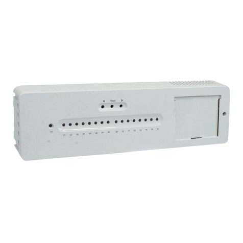
The KTD control unit is used to programme and control a solar thermal systems.
Two dierent versions are available, KTD3 and KTD5, which are used in
combination with R586S, R586S-0 and R586S-1 circulation groups.
The control unit is user-friendly thanks to its backlight graphic display, four
buttons, handy programming assistant and on-line help pages.
The KTD control unit has inputs for temperature probes type Pt1000, a relay
output for controlling an electronic circulator, and one or two relay outputs
for commanding a electronic circulator (predisposition for commanding
circulator by PWM or 0-10 V signal) and one or two relay outputs for other
additional functions.
The programs on the control unit allows to set various system congurations.
Operation control functions range from the mere reading of the current
measured values to long-term system monitoring and analysis by means of
charts and statistics. Numerous other functions complete the possibilities
oered by the KTD control unit:
• at any time, you can reset the previous values or, if necessary, the
manufacturer's default values;
• the menu locking function prevents any unwanted modication of the
operating parameters set during the unit programming phase;
• the anti-lockout function activates the pump or valve connected to the relay
for 5 seconds, at regular intervals, to prevent any possible lockout due to a
lengthy period of non-use;
• the anti-legionella function heats the boiler to a high temperature at xed
time intervals.
The KTD allows also to view the thermal energy level produced by the solar
thermal system thanks to the setting of certain additional parameters (e.g.
glycol type and percentage, and system ow rate).
Versions and product codes
Serie Product code N° of input for tempe-
rature probe
N° of included tempe-
rature probe
KTD3 KTD3Y003 3 3
KTD5 KTD5Y006 6 4
Optionals
• KTDPY001: overvoltage protection
• KTDSY001: temperature probe Pt1000 (180 °C)
Technical data
• Operational room temperature range: 0÷40 °C
• Operational room humidity range: max. 85 %
• Supply voltage: 100÷240 Vac
• Frequency: 50÷60 Hz
• Power consumption: 0,5÷2,5 W (low consumption in standby)
• Pt1000 probes easuring range: -40÷300 °C
• Power outputs: - mechanical relay: 460 VA resistive / 460 W inductive
- electronic relay: 5÷120 W inductive
• Output to control the ErP circulator: - PWM frequency 1 kHz, level 10 V
- 0-10 V tollerance 10 %, for load 10 KΩ
• Internal fuse: 2 A / 250 V slow blow
• Protection degree: IP40
• Protection class: II
Main characteristics
• Outputs 0-10 V / PWM to control the ErP circulator
• Casing: in 2 parts, ABS
• Type of installation: integrated in the circulation groups (R586S, R586S-0,
R586S-1) or separate on the wall
• Display: graphic display, 128 x 64 points
• Signalling: 1 multi-colour LED
• Programming: 4 buttons
• 18 languages selectable
• Guided installation
• Compliance: - Low voltage 2006/95/EC
- Electromagnetic Compatibility Directive 2004/108/EC
Operating characteristics
Functions KTD3 KTD5
Inputs for Pt 1000 probes 3 6
Pt1000 probes supplied 3 4
Relays outputs:
- mechanical relay
- electronic relay
2 (R1 - R2)
-
1 (R3)
2 (R1- R2)
Number of system conguration 27 42
Measurement of thermal energy SI SI
Measurement of thermal energy via VFS sensor NO SI (x 2)
Times and temperat. controlled by thermostat function SI SI
Anti-legionella protection via solar system SI SI
Anti-legionella protection via auxiliary heat generator SI SI
Anti-freezing protection SI SI
Net communication CAN Bus CAN Bus
Additional function for not used relays
• Solar By-pass
• Back-up heating control
• Solar panel cooling
• Increase the return ow
• Anti-legionella function
• Tank transfering
• Universal ΔT
• Thermostat 2
• Control of solid fuel boiler
• Signalling with activated protective function
• Signalling with new information message
• Pressure monitoring
• Booster for fast start-up of the system
• Heating circuit
• Parallel operation with R1
• Parallel operation with R2
KTD
2
0244EN June 2016
Solar thermal SyStem
Control unit
KtD
Typical applications
Warning.
The following illustrations should be viewed only as schematic
diagrams showing the respective hydraulic systems, and do not claim
to be complete. The controller does not replace safety devices under
any circumstances. Depending on the specic application, additional
system components and safety components may be mandatory, such
as check valves, non-return valves, safety temperature liwithers, scalding
protectors, etc., and must therefore be provided.
Symbol Meaning
Circulator
Valve
3-way Valve
R2 on
Heat exchanger
Solar
Probe
Radiator
Symbol Meaning
Chiller
Wood boiler
Accumulator
Auxiliary heating
Auxiliary heating
Swimming pool
Typical application for KTD3 and KTD5
Solar
S1
R1(V1)
S2
1
Solar with swimming pool + heat exchanger
S1
R1(V1)
S4
S2
R2(V2)
9
Solar + boiler double coil
S1
R1(V1)
S2
S3
R3
11
Double solar
S1 S4
S2 S3
R1(V1) R2
27
Typical application only for KTD5
Solar, accumulator and wood boiler
S1
R1(V1)
S2
S4
R2(V2)
S3
29
Solar with thermostat and pre-heating
S1
R1(V1)
S2 S4
R3
S3
R2
32
Double solar, heat exchanger, 2 circulators
S1 S5
R1(V1)
R3
R2(V2)
S4
S2
42
Solar 3 accumulators and 3 valves
S1
S2 S3 S4
R1(V1)
R2
R3
37
Note.
For other possible applications refer to the instruction manual.
Signal and command elements
The user interface of the KTD control unit consists of a graphic display,
a signalling LED and 4 buttons. The dot matrix display (1) indicates the
operation of the KTD control unit via text and graphics. The signalling LED (2)
is multi-colour and can assume the following status conditions:
• xed green light if a relay is activated
• xed red light if“OFF”mode is selected
• slow red ashing in“manual”mode
• fast red ashing if there is an error.
Using the 4 buttons (3, 4), you can access the various functions of the control
unit. The “esc” button (3) is used to enter or quit the menu; when it is pressed,
the control unit asks for conrmation that the modications must be stored.
The function of each of the other three buttons (4) is shown in the row of the
display just above the buttons themselves
The right-hand button is only used to choose and conrm a function.
Examples of the button functions:
Button Function
+/- increase/reduce a value
▼/▲scroll up/down through the menu
yes/no conrm/refuse
Info more information
Back go backwards
ok conrm your choice
Conrm conrm the setting
Meaning of the symbols on the display:
Symbol Meaning
Circolator (the symbol rotates if the circulator is working)
Valve (in black is indicated the ow direction)
Solar panel
Boiler or accumulator
Swimming pool
Temperature probe
Heat exchanger
Attention / Error message
New information
3
0244EN June 2016
Solar thermal SyStem
Control unit
KtD
Installation
Warning.
The installation and programming of the KTD control unit, and the
initial start-up of the solar thermal system, should only be carried
out by expert personnel who must scrupulously respect current
laws and comply with the Standards, project indications, technical
documentation and assembly instructions supplied with the device.
The KTD control unit can be installed integrated in the R586S, R586S-0,
R586S-1 circulation groups or separated on the wall.
The permissible lengths of the connecting cables are:
• Solar panel and external probe: < 30 m
• Other Pt1000 probes: < 10 m
• CAN Bus: < 3 m
• PWM o 0-10 V: < 3 m
• Mechanical relay: < 10 m
• Electronic relay (only for KTD5): < 10 m
Note.
For installation and conguration steps, refer to the instruction
manual.
Dimensions
B C
A
Product code A [mm] B [mm] C [mm]
KTD3Y003 163 110 52
KTD5Y006 163 110 52
Product specication
KTD3
Dierential control unit for programming and controlling the operation
of the solar thermal system. To be used with the R586S, R586S-0 and
R586S-1 circulation group. Backlight graphic dot matrix display (128x64). 4
buttons, 1 multi-colour signalling LED. Programming assistant and on line
help pages. 3 inputs for Pt1000 temperature probes (3 probes included),
2 mechanical relay outputs. 27 possible system congurations. Thermal
energy measurement function. Anti-legionella protection function via
activation of the solar thermal system. Menu locking function to prevent
any unwanted modication of the operating parameters. Anti-lockout
function with activation (for 5 sec) of circulator or valve connected to relay
output. Value reset function (previous or default values). Supply voltage 230
V AC ± 10 %. 2 A internal protection fuse, slow-blow type 250 V. ABS casing.
Dimensions 163x110x52mm.
KTD5
Dierential control unit for programming and controlling the operation
of the solar thermal system. To be used with the R586S, R586S-0 and
R586S-1 circulation group. Backlight graphic dot matrix display (128x64). 4
buttons, 1 multi-colour signalling LED. Programming assistant and on line
help pages. 6 inputs for Pt1000 temperature probes (5 probes included),
2 mechanical relay outputs. 42 possible system congurations. Thermal
energy measurement function. Anti-legionella protection function via
activation of the solar thermal system. Menu locking function to prevent
any unwanted modication of the operating parameters. Anti-lockout
function with activation (for 5 sec) of circulator or valve connected to relay
output. Value reset function (previous or default values). Supply voltage 230
V AC ± 10 %. 2 A internal protection fuse, slow-blow type 250 V. ABS casing.
Dimensions 163x110x52mm.
4
0244EN June 2016
Solar thermal SyStem
Control unit
KtD
Additional information
For additional information please check the website www.giacomini.com or contact the technical service: '+39 0322 923372 6+39 0322 923255 *[email protected]
This pamphlet is merely for information purposes. Giacomini S.p.A. retains the right to make modications for technical or commercial reasons, without prior notice, to the items described in
this pamphlet. The information described in this technical pamphlet does not exempt the user from following carefully the existing regulations and norms on good workmanship.
Giacomini S.p.A. Via per Alzo, 39 - 28017 San Maurizio d’Opaglio (NO) Italy

Other manuals for KTD3

1

This manual suits for next models

3

Other Giacomini Control Unit manuals

Giacomini R160 User manual

Giacomini

Giacomini R160 User manual

Giacomini PM100W User manual

Giacomini

Giacomini PM100W User manual

Giacomini R453HY011 User manual

Giacomini

Giacomini R453HY011 User manual

Giacomini R701F User manual

Giacomini

Giacomini R701F User manual

Giacomini HDB Series User manual

Giacomini

Giacomini HDB Series User manual

Giacomini KPM36Y001 User manual

Giacomini

Giacomini KPM36Y001 User manual

Giacomini R140 User manual

Giacomini

Giacomini R140 User manual

Giacomini INAIL N143 User manual

Giacomini

Giacomini INAIL N143 User manual

Giacomini KPM30 Series Manual

Giacomini

Giacomini KPM30 Series Manual

Giacomini R140D User manual

Giacomini

Giacomini R140D User manual

Giacomini R298 Series User manual

Giacomini

Giacomini R298 Series User manual

Giacomini GE550Y022 Operating instructions

Giacomini

Giacomini GE550Y022 Operating instructions

Giacomini KPM35 User manual

Giacomini

Giacomini KPM35 User manual

Giacomini R401TG User manual

Giacomini

Giacomini R401TG User manual

Giacomini R314DN User manual

Giacomini

Giacomini R314DN User manual

Giacomini DB Series User manual

Giacomini

Giacomini DB Series User manual

Giacomini R401TG User manual

Giacomini

Giacomini R401TG User manual

Giacomini P146M User manual

Giacomini

Giacomini P146M User manual

Giacomini R586RY121 User manual

Giacomini

Giacomini R586RY121 User manual

Popular Control Unit manuals by other brands

Woodward easYgen-100 Series Technical manual

Woodward

Woodward easYgen-100 Series Technical manual

Gi MP48 DF installation manual

Gi

Gi MP48 DF installation manual

GEA VARIVENT 24/7 PMO Original operating instructions

GEA

GEA VARIVENT 24/7 PMO Original operating instructions

Siemens SIMATIC ET 200SP manual

Siemens

Siemens SIMATIC ET 200SP manual

TEXA TMD MKG installation manual

TEXA

TEXA TMD MKG installation manual

Grundfos PLV Series instructions

Grundfos

Grundfos PLV Series instructions

Watts WFC-03 HCM RF 230 Quick installation guide

Watts

Watts WFC-03 HCM RF 230 Quick installation guide

Bticino RW4575CW manual

Bticino

Bticino RW4575CW manual

Phoenix Mecano Dewert Okin CU458-2 installation instructions

Phoenix Mecano

Phoenix Mecano Dewert Okin CU458-2 installation instructions

Berker 75318102 Operation instructions

Berker

Berker 75318102 Operation instructions

Flowserve MASTER STATION IV EEP-SN4001 User instructions

Flowserve

Flowserve MASTER STATION IV EEP-SN4001 User instructions

Miele DSM 408 Operating and installation instructions

Miele

Miele DSM 408 Operating and installation instructions

Honeywell Esser IQ8TAL Installation instruction

Honeywell

Honeywell Esser IQ8TAL Installation instruction

Ampac GasRelease 2980-0001 installation guide

Ampac

Ampac GasRelease 2980-0001 installation guide

LS RESEARCH TiWi user guide

LS RESEARCH

LS RESEARCH TiWi user guide

Siemens ANT792-6MN Compact operating instructions

Siemens

Siemens ANT792-6MN Compact operating instructions

HEIDENHAIN TNC 426 PB/M Technical manual

HEIDENHAIN

HEIDENHAIN TNC 426 PB/M Technical manual

Danfoss PCVD instructions

Danfoss

Danfoss PCVD instructions

manuals.online logo
manuals.online logoBrands
  • About & Mission
  • Contact us
  • Privacy Policy
  • Terms and Conditions

Copyright 2025 Manuals.Online. All Rights Reserved.