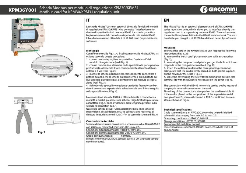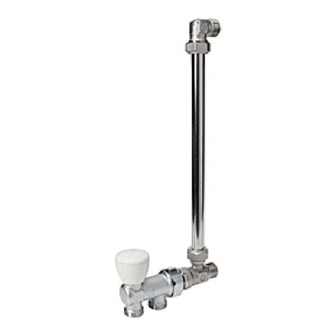
1b
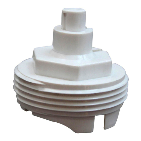
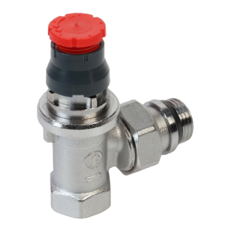
1a IT - Montaggio delle teste termostatiche Giacomini sulla valvola.
(1a) Nel caso di valvola con protezione da cantiere, dopo aver svitato in senso antiorario
il cappuccio rosso, sganciare la protezione da cantiere facendo leva sulla base mediante l’ausilio di un cacciavite. (1b) Nel caso di valvola con volantino manuale,
con l’ausilio di un piccolo cacciavite o punteruolo si proceda alla rimozione della parte superiore della manopola e successivamente del piolino di regolazione.
EN - Assembly of Giacomini thermostatic heads to the valve. (1a) Unscrew the red cap fully counter clockwise and remove the protection cap by using a
screwdriver as a lever. (1b) By using a little screwdriver or a centre punch, remove the upper part of the handle and afterwards of the adjustment pip. Through a
counter clockwise rotation, proceed by removing the handwheel and at the end remove the cane.
FR - Montage de têtes thermostatiques Giacomini sur le robinet. (1a) Après avoir complètement ouvert le capuchon rouge dans le sens inverse des aiguilles
d’une montre, enlever le capuchon de chantier en faisant levier à la base du capuchon avec un tournevis. (1b) A l’aide d’un petit tournevis ou d’une pointe on enlèvera
supérieure la partie supérieure du volant ainsi que du clou de réglage. Par simple rotation dans le sens des aiguilles d’une montre on ôte le volant puis on enlève la bague.
DE - Montage desGiacomini Thermostatkopfs auf das Ventil. (1a) Drehen Sie die rote Kappe entgegen dem Uhrzeigersinn ganz ab. Danach wird mit
einem einen Schraubendreher die Schutzkappe abgehebelt. (1b) Wird mit einen kleinen Schraubendreher zunächst der Stift aus dem Oberteil gezogen und
anschließend das Plattchen abgenommen.
NL - Montage van de thermostatische regelelementen Giacomini op de radiatorkranen. (1a) Eerst dient het rode handwiel in tegenwijzerzin
losgeschoefd te worden. Nadien de basis van de kunstsof werfkap wegnemen met behulp van een schroevedraaier. (1b) Met behulp van een kleine
schroevedraaier, het bovenste dekseltje van het handwiel en nadien het metalen stiftje gedemonteerd te worden. Vervolgens het handwiel in tegenwijzerzin
losschroeven en de kunststof basis wegnemen.
ES - Montaje del cabezal termostático Giacomini sobre la válvula. (1a) Desenroscar el tapón rojo y quitar la base de plàstico con la ayuda de un
destornillador.(1b) Primero extraer la tapa frontal del volante con ayuda de un pequeño destornillado o punzón. Posteriormente extraer el pasador de
PT - Montagem das cabeças termostáticas Giacomini na válvula. (1a)No caso de válvulas com proteção de obra, depois de desapertar a tampa vermelha
no sentido anti-horário, deve desencaixar a proteção de obra, fazendo alavanca sobre a base com uma chave de fendas. (1b) Com auxílio de uma pequena chave
de parafusos, procede-se à remoção da parte superior do manípulo e seguidamente da cavilha de regulação. Pela simples rotação anti-horária, procede-se à
RU - Монтаж термостатических головок Джакомини с клапаном Джакомини. (1a) Для монтажа термостатических головок Джакомини с
клапаном после поворота против часовой стрелки красного кожуха следует снять пластиковый маховичок при помощи отверти. (1b) Для монтажа
термостатических головок Джакомини с клапаном при помощи отвертки надо вначале сдвинуть верхнюю часть ручки, и затем регулировочный
фиксатор.Поворотом против часовой стрелки можно удалитр маховик, и затем регулировочный фиксатор.
PL - Montaż głowicy termostatycznej Giacomini na zaworze. (1a) Odkręć czerwoną nakrętkę całkowicie, przeciwnie do ruchu wskazówek zegara i zdejmij
osłonę zabezpieczającą [kołpak] za pomocą śrubokręta używając go jako dźwigni. (1b) W przypadku zaworu z pokrętłem ręcznym usuń górną pokrywę
uchwytu używając małego śrubokręta lub punktaka, a następnie sworzeń regulacyjny. Poprzez obrót w lewo usuń pokrętło ręczne i na końcu zdejmij tuleję
6
IT -
Per un ottimale funzionamento della testa termostatica il montaggio della valvola deve
avvenire con asse del volantino di protezione (a) o di manovra (b) in posizione orizzontale.
EN - In order to obtain the optimal function of the thermostatic head, the valve must be
installed with the axis of the protection cap (a) or the manual handwheel (b) in horizontal
position.
FR - Pour un fonctionnement optimal de la tête thermostatique, le robinet doit être monté
de telle manière que l’axe du volant soit en position horizontale.
DE - Für eine fehlerfreie Funktion des Thermostatkopfs sollte das Ventil nur in waagerechter
Position montiert werden.
NL - Voor een goede werking dient het thermostatisch regelelement steeds horizontaal gemonteerd te worden.
ES - Para que el funcionamiento de la cabeza termostática sea correcto, el montaje de la válvula debe efectuarse de forma que el eje del volante queden en posición horizontal.
PT - Para um ótimo funcionamento da cabeça termostática, a montagem da válvuladeve ser efetuada com o eixo do volante/manípulona posição horizontal.
RU - Для оптимальной работы термостатической головки клапан должен монтироваться в горизонтальном положенииосимаховика.
PL -
IT - Aprire completamente la testa.
EN - Open fully the head.
FR - Ouvrir complètement la tête.
DE -Thermostatkopf ganz aufdrehen.
NL - Het thermostaatelement volledig openen.
ES -Abrir completamente el cabezal termostático.
PT - Abrir completamente a cabeça.
RU - Откройте полностыо термостатическую головку.
PL - Otwórz całkowicie głowicę
2
IT - Agganciare la testa alla valvola.
EN - Connect the head to the valve.
FR - En foncer la tête surle robinet.
DE - Thermostatkopf an das Ventil anbringen.
NL -Het thermostaatelement op het kraanlichaam plaatsen.
ES - Acoplar el cabezal a la válvula, haciendo coincidir las
pestañas sobre los resaltes de la válvula.
PT -Encaixara cabeçana válvula.
RU - Защелкните головку на клапане.
PL - Nałóż głowicę na zawór
3
IT - Chiudere completamente la testa.
EN - Close fully the head.
FR - Fermer complètement la tête.
DE - Thermostatkopf ganz zudrehen.
NL - Het thermostaatelement volledig sluiten.
ES - Cerrar completamente el cabezal termostático.
PT - Fechar completamente a cabeça.
RU - Полностыю закройте головку.
PL - Zamknij całkowicie głowicę
4
IT - Aprire la testanellaposizione desiderata.
EN - Open the head into the desired calibration position.
FR - Positionner la tête sur la position désirée.
DE - Thermostatkopf so weit aufdrehen, bis er sichinder
gewünschten.
NL - Het thermostaatelement op de gewenste positie instellen.
ES-Abrirel cabezal hastala posición de laregulación deseada.
PT - Abrir a cabeça até à posição pretendida.
RU - Откройте головку до нужного уровня.
PL - Ustaw głowicę w żądanej pozycji
5
2 3
8
IT -
In caso di manutenzione é possibile sostituire l’anello O-ring dell’asta svitando la calottina del vitone mediante l’ausilio di una chiave esagonale da 11
EN -
For maintenance purposes, it is possible to replace the O-ring seal on the valve stem by unscrewing the small hexagonal retaining nut using an 11
mm spanner. This operation may be carried out without draining the system.
FR -
Dans le cadre d’une maintenance de l’installation il est possible de changer le joint O-ring situé sur l’axe du mécanisme. Pour cela on dévissera, à l’aide
d’une clef hexagonale de 11 mm, l’écrou situe sur l’axe. Cette opération est possible l’installationétant sous pression.
DE -
Zu Wartungszwecken lässt sich der O-Ring auf der Spindel im Ventil ersetzen, indem man die kleine Sechskant-Überwurfmutter mit einem 11 mm.
Schraubenschussel löst. Dieser Vorgang ist möglich, ohne zuvor das Wasser aus derAnlage ablassen zu müssen.
NL -
In geval van onderhoud kan de O-Ring rond de spindel vervangen worden door het messing moertje van het binnenwerk los te schroeven met
behulp van een sleutel 11 mm. Deze handeling kan eveneens worden uitgevoerd terwijl de installatie in bedrijf is.
ES -
En mantenimiento es possible sustituir el anillo tórico del eje desatornillando el casquillo hexagonal roscando de la montura, mediante una llave de 11 mm. Esta operación puede
ser efectuada con la instalación en funcionamiento.
PT -
Em caso de manutenção é possível substituir o O-ring da haste, desapertando a calote do corpo da válvula com o auxílio da chave hexagonal de 11 mm. Esta operação pode ser
efetuada com a instalação em funcionamento.
RU -
В случае необходимости проведения ремонтных работ, заменить уплотнительное кольцо можно, открутив гайку при помощи шестигранного ключа на 11мм. Эта операция
может быть осуществлена также приработе оборудования.
PL - W celach konserwacyjnych można wymienić uszczelkę O-ring na trzpieniu zaworu odkręcając sześciokątną nakrętkę ustalającą za pomocą klucza imbusowego 11 mm.
Ta operacja może być przeprowadzona przy pracującej instalacji.
7
IT -
togliendo la parte superiore della manopola e del piolino che andrà poi rimontato nella posizione corrispondente al numero rilevato
EN -
upper part of the handle and the pip, that shall be then re-assembled into the position corresponding to the number taken from the
FR -
En cas de fonctionnement « manuel » le réglage du débit pet être fait en enlevant délicatement la partie
supérieure de la tête manuel et en positionnant le clou de réglage sur la position déterminer a partir du diagramme d’équilibrage.
DE - Bei „Hand-„ Betrieb lasst sich die Einstellung durch Entfernen des Stiftes aus dem Oberteil errechen. Bei Wiedereinbau ist die
Position zu wählen, die dem Wert im entsprechenden Druckverlustdiagram entspricht.
NL - In geval van “manuele bediening” kan een
voorinstelling gedaan worden door het wegnemen van het bovenste dekseltje van het handwiel en het metalen stiftje. Nadien wordt het
metalen stiftje teruggeplaatst in een positie die afgelezen wordt uit het drukverliesdiagramma. ES - En el caso de funcionamiento “manual”
la regulación micrométrica puede efectuarse retirando la tapa frontal del volante, extrayendo el pasador de regulaciòn y ubicándolo
en la posiciòn correspondiente según el diagrama de regulación.
PT - Em caso de funcionamento “manual”, a regulação micrométrica pode ser efectuada tirando a parte superior
do manípulo e da cavilha que será posteriormente montada na posição correspondente ao número obtido sobre o diagrama de equilibragem. RU - При использовании клапана
в “ручном режиме” установка режимов может осуществляться путем изъятия верхней части ручки и регулировочного фиксатора, который потом будет вновь установлен в
соответствующую позицию под номером, соответствующем значению, обозначенному на шкале. PL - W przypadku zaworów z pokrętłem ręcznym, w przypadku pracy w trybie
"ręcznym", regulację mikrometryczną można przeprowadzić poprzez zdjęcie górnej pokrywy pokrętła i sworznia, które należy ponownie umieścić w pozycji odpowiadającej numerowi
określonemu w schemacie kalibracji.
IT - Dati tecnici
Attacco ferro 3/8”(tranne serie D), 1/2”, 3/4”
Pressione max d’esercizio per applicazioni manuali: PN16
Campo di temperatura: 5÷110 °C
Taratura min. in abbinamento a teste termostatiche R460, R468C,
R468, R469, R470:8 °C in posizione *
Pressione max d’esercizio in abbinamento a teste termostatiche:
10 bar
Protezione da cantiere: la protezione da cantiere consente di
parzializzare la portata della valvola. Ruotando il cappuccio rosso
in senso antiorario si apre la valvola mentre con rotazione oraria
si ottiene la sua chiusura.
A rotazioni d’angolo del cappuccio rosso di 36° corrispondono
variazioni di temperatura pari a 1 °C. La protezione con cappuccio
chiuso a fondo consente di superare abbondantemente
pressioni statiche di 10 bar conimpianto spento.
dell’impianto solo dopo aver collegato i corpi scaldanti onde
evitare, in caso di danneggiamenti accorsi al meccanismo, di
provocare allagamenti.
EN - Technical data
Iron connection 3/8”(except for D-series), 1/2”, 3/4”
Max working pressure for manual applications: PN16
Temperature range: 5÷110 °C
Min calibration with thermostatic heads R460, R468C, R468,
R469,R470:8 °C in position *
Max working pressure withthermostatic heads: 10 bar
the valve.
By rotating the red cap anticlockwise the valve opens, by
rotating it clockwise the valve closes.
For every 36° rotation of the red cap there is a temperature
change of1 °C.
The completely closed red cap allows to go over the static
However it’s better to carry out a pressure seal test only after
the connection of the radiators, in order to avoid damages and
FR - Données Techniques
Jonction fer 3/8”(l’exceptionsérie D), 1/2”, 3/4”
Pression max de service pourapplications manuelles: PN16
Température max de service: 5÷110 °C
Etalonnage min en association aux têtes thermostatiques R460,
R468C,R468,R469,R470: 8 °C en position *
Pression max de service en association aux têtes
thermostatiques:10 bar
Capuchon de chantier: le capuchon de protection permet de
partialiser la portée de la vanne. En tournant le capuchon rouge
dans le sens inverse à celui des aiguilles d’une montre, la vanne
s’ouvre, alors que avec une rotation dans le sens des aiguilles d’une
montre, la vanne se ferme. Les rotations d’angle du capuchon
rouge de 36° correspondent à variations de température de 1 °C.
Le capuchon fermé à fond permet de dépasser abondamment
pressions statiques de 10 bar avec installation fermée. On conseille
d’éviter de provoquer inondations, en cas de endommagement
du mécanisme.
DE - Technische Daten
3/8”(außer Serie D), 1/2”, 3/4”Kupplung für Eisen
Max Betriebsdruck für manuellen Anwendungen: PN16
Max Betriebstemperatur: 5÷110 °C
Min Eichung in Paarung mit Thermostatkopfen R460, R468C,
R468, R469, R470: 8 °C in* Stellung
Max Betriebsdruck in Paarung mit Thermostatkopfen:10 bar
Bauschutzkappe: die Bauschutzkappe erlaubt die Drosslung
Drehung entgegen dem Uhrzeigersinn der roten Kappe.
Während es schließt sich mit der Drehung im Uhrzeigersinn.
Eine Drehung der roten Kappen von 36° entsprechen
einer Temperaturänderung von 1 °C. Der Schutz mit tief
geschlossene Kappe erlaubt statische Drucken von 10 bar
mit geschlossene Anlage reichlich zu übersteigen. Man ratet
auf jeden Fall Druckdichtigkeitsprüfungen der Anlagen nur
nach der Verbindung der Radiatoren durchzuführen, um
Überschwemmungen zu vermeiden, falls Beschädigungen an
der Einrichtung vorfallen sind.
NL - Technische gegevens
Universele schroefdraadaansluiting 3/8” (behalve serie D), 1/2”
, 3/4”
Maximale werkdruk bij manuele bediening: PN16
Maximale watertemperatuur: 5÷110 °C
Minimum ruimtetemperatuur in combinatie met thermostatisch
element R460, R468C, R468, R469, R470:8 °C inpositie *
Maximale werkdruk bij thermostatische bediening:PN10
De blauw/rode beschermkop laat toe om het debiet door de
radiatorkraan te regelen: door het rode handwiel te draaien in
tegenwijzerszin wordt de kraan geopend, door het handwiel te
draaien in wijzerszin wordt de kraan gesloten.
Het draaien van het handwiel over een hoek van 36° beïnvloedt
de ruimtetemperatuur met 1°C.
Met de blauw/rode beschermkop in de volledig gesloten positie
mag de statische groter zijn dan 10bar wanneer de installatie is
uitgeschakeld.
Het afpersen van de installatie dient steeds te gebeuren na de
aansluiting van de verwarmingslichamen aan het leidingnet.
ES - Datos técnicos
Conexiones rosca hierro: 3/8”(excepto de la serie D), 1/2”, 3/4”
Fluido: Aguacaliente
Temperatura máx.de ejercicio: 5÷110 °C
Presión máxima de ejercicio con accionamiento manual: PN16
Temperatura mínima con cabezal termostático R460, R468C,
R468, R469, R470:8 °C en posiciòn *
Presión máxima de ejercicio con cabezal termostático: 1MPa
(10 bar)
Presión diferencial máxima: 1,4 bar (3/8”, 1/2”); 0,7 bar (3/4”)
Protección de obra: El volante de protección de obra permite
accionar la válvula durante los trabajos de instalación. El
capuchón rojo actúa como volante de maniobra. Una
rotación del volante de 36º corresponde a una variación de
la temperatura de 1 °C. Con el volante de protección de obra
totalmente cerrado se pueden superar ampliamente presiones
estática de 10 bar con la instalación parada. No obstante, no es
aconsejable efectuar pruebas de presión de la instalación antes
de realizar las conexiones a los radiadores para evitar provocar
inundaciones en casode daños producidos al mecanismo.
PT - Dados técnicos
Ligação 3/8”(exceto para série D), 1/2”, 3/4”
Pressão máximade trabalhopara aplicações manuais:PN16
Temperatura máxima de trabalho: 5÷110 °C
Equilibragem com ligação das cabeças termostáticas R460,
R468C, R468,R469,R470: 8 °C na posição *
Pressão máximade trabalhoc/ cabeças termostáticas:10 bar
Pressão diferencial máxima: 1,4 bar (3/8”, 1/2”); 0,7 bar(3/4”)
Protecção de obra: a protecção de obra permite parcializar o
caudal da válvula. Rodando o manípulo vermelho no sentido
anti-horário abre-se a válvula enquanto que com a rotação
horária se obtém o fecho.
As rotações de ângulo do manípulo vermelho de 36°
correspondem variações de temperatura de cerca de 1 °C.
A protecção com o manípulo totalmente fechado permite
superar pressões estáticas de 10 bar com a instalação desligada.
Em qualquer caso, aconselha-se a efectuar os testes de pressão
da instalação depois de estarem ligados os radiadores de modo
a evitar, em caso de danos ocorridos no mecanismo da válvula,
saída de águae consequentes alagamentos.
RU - Технические данные
Диаметры патрубков 3/8”(кроме серииD),1/2”, 3/4”
Максимальное рабочее давление клапанов с механической
регулировкой:PN16
Максимальная рабочая температура: 5÷110 °C
Минимальная температура настройки термостатических
головок R460, R468C, R468, R469, R470: 8 °C в положении *
Максимальное рабочее давление клапанов, регулируемых с
помощью термоголовки: 10 бар
Максимальное дифференциальное давление: 1,4 bar (3/8”,
1/2”); 0,7 bar (3/4”)
Защита клапана при запуске: защита клапана при запуске
позволяет поделить на части подачу воды в клапан. При
вращении красного колпачка против часовой стрелки,
клапан открывается, а при вращении по часовой стрелке
- закрывается. Положениям красного колпачка при его
вращении на угол в 36° соответствуют значения температуры
в 1 °С. Защита при колпачке, закрытом вовнутрь, позволяет
значительно превысить значения статических нагрузок
10 бар при выключенном оборудовании. Рекомендуется
каждый раз проводить испытания по герметичности системы
только после подсоединения отопительных приборов, чтобы
избежать в случае повреждений в клапане протечки.
PL - Dane techniczne
Przyłącze gwintowane 3/8 "(z wyjątkiem serii D), 1/2", 3/4"
Maksymalne ciśnienie robocze dla zaworów z regulacją ręczną: PN16
Zakres temperatury: 5 ÷ 110° C
Min. Nastawa z głowicami termostatycznymi R460, R468C, R468,
R469, R470: 8° C na pozycji *
Maksymalne ciśnienie robocze z głowicami termostatycznymi:
10 bar
Max różnica ciśnień: 1,4 bar (3/8", 1/2"); 0,7 bar (3/4")
Osłona zabezpieczająca: umożliwia częściową regulację
przepływu przez zawór. Obrót w kierunku przeciwnym do
ruchu wskazówek zegara powoduje otwarcie zaworu, a obrót
w kierunku zgodnym z ruchem wskazówek zegara zamyka zawór.
Każdy obrót osłony o 36° odpowiada zmianie temperatury
o 1° C.
Całkowicie zamknięta osłona zabezpieczająca utrzyma ciśnienie
statyczne 10 barów przy wyłączonym systemie. Jednak nie
zaleca się przeprowadzania testów ciśnieniowych układu przed
podłączeniem elementów grzewczych, aby uniknąć zalania w
przypadku uszkodzenia osłony.
R400
W przypadku zamontowania głowicy termostatycznej na korpusie zaworu, aby uniknąć nadmiernego obciążania uszczelki wkładki termostatycznej (z wynikającym z
tego ryzykiem zakleszczenia i zablokowania) w okresie letnim, wskazane jest ustawienie głowicy w pozycji maksymalnego otwarcia - pozycja oznaczona symbolem .
W przypadku wadliwego działania zaworu istnieje możliwość wymiany o-ringu, odkręcając nakrętkę za pomocą klucza imbusowego 11 mm. Jeśli problem nadal
występuje, można również wymienić kompletną wkładkę za pomocą odpowiedniego klucza R400.
Wymiana wkładki za pomocą klucza R400 nie jest możliwa dla następujących zaworów: R421FX004, R422FX004, R401FX004, R402FX004, R401DX004, R402DX004.
With thermostatic head installed on the valve body, to avoid excessive loads on the seal gasket of the thermostatic bonnet (with the resulting risk of jamming and locking)
during the summer, it is recommended to place the handwheel of the thermostatic head in the fully open position, marked by the symbol .
In case of malfunction of the valve
it is possible to replace the O-ring, by unscrewing the nut using an hexagonal wrench 11 mm If the problem persists is also possible to replace the complete bonnet using the
appropriate key R400.
The bonnet replacement with R400 key, is not possible for the following valves: R421FX004, R422FX004, R401FX004, R402FX004, R401DX004, R402DX004.
Aby zapewnić optymalne funkcjonowanie głowicy termostatycznej, zawór musi być zamontowany z osią pokrętła ręcznego (a) lub osłony zabezpieczającej (b) w pozycji poziomej
