manuals.online logo
Brands
  1. Home
  2. •
  3. Brands
  4. •
  5. GLITZHOME
  6. •
  7. Indoor Furnishing
  8. •
  9. GLITZHOME 5022000 User manual

GLITZHOME 5022000 User manual

Assembly Instruction
TWO DOOR WOOD CABINET
1
Explosive View
M
L
B
C
A
G
F
J
K
H
I
E
L
L
N
o
D
PRE-ASSEMBLY PREPARATION
WARNING: MAXIMUM LOAD NOT EXCEED 10LBS ON SHELVES.
•CAUTION: Assembly will require at least 2 adults.
•
DO NOT use power tools.To prevent serious injury or death, this product is equipped with a wall
anchoring system. Before this product can be used, the wall anchoring system must be installed as
directed in the assembly instructions.
CARE AND CLEANING: DO NOT scratch or chip the finish. DO NOT use abrasive chemicals for cleaning.
Clean with mild soap on a soft rag. Rinse and dry thoroughly.
•
•
MAINTENANCE: Check bolts/screws periodically and tighten if necessary.•
WARNING: DO NOT USE if this product become damaged, and/or components are broken or missing.
REMINDER: Please DO NOT fully tighten all bolts until metal frame assembly is complete.
2
PARTS LIST
Qty: 2 Qty: 1
LEFT FRAME (A) BACK BOTTOM
SUPPORT BAR (D)
RIGHT FRAME (B)
BACK CROSS BAR (E)
FRONT BOTTOM
SUPPORT BAR (C)
LEFT WOOD PANEL (F) RIGHT WOOD PANEL (G) RIGHT DOOR (H)
Qty: 1 Qty: 1
Qty: 1 Qty: 1 Qty: 1 Qty: 1
LEFT DOOR (I) BOTTOM PANEL (J) TOP PANEL (K) BACK PANEL (L)
Qty: 1 Qty: 1 Qty: 1 Qty: 3
PART DESCRIPTION QTY QTY
A
J
K
L
LEFT FRAME
RIGHT FRAME
1
1
1
1
2
1
1
1
1
3
B
C
D
E
F
G
I
PART DESCRIPTION
FRONT BOTTOM SUPPORT BAR
BACK BOTTOM SUPPORT BAR
BACK CROSS BAR
LEFT SIDE PANEL
RIGHT SIDE PANEL
LEFT DOOR
BOTTOM PANEL
TOP PANEL
BACK PANEL
1
M1
TOP FIXED SHELF PANEL
N1
MIDDLE MOBILE SHELF PANEL
1
HRIGHT DOOR
O2
BACK PLASTIC STRIP
3
TOP FIXED SHELF
PANEL (M)
MIDDLE MOBILE PANEL
(N)
BACK PLASTIC STRIP
(O)
Qty: 1 Qty: 2Qty: 1
CAM (1)
PHILLIPS SCREW (5)
CAM LOCK (2) PHILLIPS SCREW (3) UMBRELLA HEAD BOLT
(4)
Qty: 8 Qty: 8 Qty: 4 Qty: 6
HARDWARE LIST
Ø15*9mm M6*25mmØ4*37mm
Qty: 6 Qty: 4
ALLEN BOLT (6)
Qty: 4 Qty: 5
Ø4*29mm M6*12mm
PIN (7) PHILLIPS SCREW (8)
Ø4*12mmØ5*22mm
ALLEN WRENCH (9)
Qty: 1 Qty: 12
WOOD DOWEL (10)
Qty: 1 Qty: 1
Ø6*30mm
GLUE (11) ANTI-TIPPING STRIP (12)
5*200mm
WALL ANCHOR (13)
Qty: 1 Qty: 1
PHILLIPS SCREW (14)
Qty: 2 Qty: 1
Ø8.5*30mm 4*25mm
STEEL PLATE (15) NOT INCLUDED
11*11*24mm
4
STEP 2
REQUIRED HARDWARE IN THIS STEP
NO. DESCRIPTION SKETCH QTY
2PCS
CAM
1
GLUE
11
STEP 1
REQUIRED HARDWARE IN THIS STEP
NO. DESCRIPTION SKETCH QTY
GLUE
11
2PCS
1CAM
1
1
F
G
Insert cam (1) into left wood panel (F) and fully
tighten. Place a small dab of glue into the adjacent
holes as shown in the diagram.
Insert cam (1) into right wood panel (G) and
fully tighten. Place a small dab of glue (11)
into the adjacent holes as shown in the diagram.
11
11
1
1
11
11
5
STEP 3
G
F
M
M
M
REQUIRED HARDWARE IN THIS STEP
NO. DESCRIPTION SKETCH QTY
4PCSWOOD DOWEL10
GLUE11
Place a small dab
of glue (11) into
the outside holes
on the edge of top
fixed shelf panel
(M) and insert
wood dowels (10)
into the holes.
STEP 4
Place top fixed shelf panel (M) on edge. Align
the cams (1) in Left wood panel (F) and right
wood panel (G) with the holes in the edge of
top fixed shelf panel (M) and slide into place
as shown in the diagram.
10
10
10
10
11
11 11
11
6
2
F
MG
2
STEP 6
STEP 5
REQUIRED HARDWARE IN THIS STEP
NO. DESCRIPTION SKETCH QTY
4PCS
1CAM
1
1
K
GLUE
11
Insert cam lock (2) into top
fixed shelf panel (M) and
tighten with phillips screw
driver.
Insert cam (1) into top panel (K) and fully tighten. Place a small dab
of glue (11) into the adjacent holes as shown in the diagram.
11
11
11
111
1
REQUIRED HARDWARE IN THIS STEP
NO. DESCRIPTION SKETCH QTY
PHILLIPS SCREW DRIVER NOT INCLUDED
2 CAM LOCK 4PCS
7
STEP 7
K
REQUIRED HARDWARE IN THIS STEP
NO. DESCRIPTION SKETCH QTY
4PCSWOOD DOWEL10
GLUE11
10
10
2
F
M
G
Carefully set the
assembled panels upright
as shown in the diagram.
Place a small dab of glue
(11) into the outside holes
of the edges of left wood
panel (F) and right wood
panel (G) and insert wood
dowels (10) into the holes.
STEP 8
Align the cams (1) in the top
panel (K) with the holes in Left
wood panel (F) and right wood
panel (G) and lower into place.
11
11
8
STEP 10
REQUIRED HARDWARE IN THIS STEP
NO. DESCRIPTION SKETCH QTY
STEP 9
K
Insert cam lock (2) into left
wood panel (F) and right wood
panel (G) and fully tighten with
phillips screwdriver.
Carefully turn the assembled parts over as shown in the diagram. Place a small dab of glue
(11) into the outside holes of the edges of left wood panel (F) and right wood panel (G) and
insert wood dowels (10) into the holes.
4PCSWOOD DOWEL10
GLUE11
10
10
10
10
11
11
11
11
REQUIRED HARDWARE IN THIS STEP
NO. DESCRIPTION SKETCH QTY
PHILLIPS SCREW DRIVER NOT INCLUDED
2 CAM LOCK 4PCS
9
STEP 11
Slide back panel (L) into the grooves of left wood panel (F) and right wood panel (G). Place
plastic strip (O) in between each back panel (L) as shown in the diagram.
L
L
L
10
STEP 12
REQUIRED HARDWARE IN THIS STEP
NO. DESCRIPTION SKETCH QTY
J
11
11
Place a small dab of glue (11)
into the outermost holes
bottom wood panel (J) as
shown in the diagram.
GLUE11
STEP 13
Align the wood dowels of left wood
panel (F) and right wood panel (G) with
the holes in bottom wood panel (J) and
lower into place.
11
11
L
L
L
J
11
A
3
STEP 14
REQUIRED HARDWARE IN THIS STEP
NO. DESCRIPTION SKETCH QTY
REQUIRED HARDWARE IN THIS STEP
STEP 15
Secure the bottom wood panel (J) to left wood panel
(F) and right wood panel (G) with phillips screw (3)
using phillips screwdriver. Fully tighten screws.
NO. DESCRIPTION SKETCH QTY
Assemble front bottom support bar (C) &
back bottom support bar (D) on left frame (A)
and right frame (B) with allen bolt (6) using
allen wrench (9). Do not fully tighten bolts.
3 4PCS
PHILLIPS SCREW DRIVER NOT INCLUDED
PHILLIPS SCREW
Ø4*37mm
4PCS6 ALLEN BOLT M6*12MM
9 ALLEN WRENCH
3
3
3
J
6
C
D
B
12
STEP 16
Carefully place the assembled metal frame over the assembled cabinet as shown in the diagram.
L
L
L
A
B
C
D
13
STEP 17
REQUIRED HARDWARE IN THIS STEP
NO. DESCRIPTION SKETCH QTY
4PCS4 ALLEN BOLT M6*25MM
6PCS5
PHILLIPS SCREW
Ø4*29MM
B
A
Attach left frame (A) and right frame (B) to the assembled cabinet with allen bolt (4) using allen
wrench (9).
Attach the the metal frame to bottom wood panel (J) with phillips screw (5) using phillips
screwdriver. Fully tighten all screws and bolts.
9 ALLEN WRENCH
PHILLIPS SCREW DRIVER NOT INCLUDED
C
D
5
5
B
A
4
4
14
STEP 19
STEP 18
REQUIRED HARDWARE IN THIS STEP
NO. DESCRIPTION SKETCH QTY
4
4
8
8
8
8
REQUIRED HARDWARE IN THIS STEP
NO. DESCRIPTION SKETCH QTY
E
With assistance, carefully turn the assembled cabinet
onto it's feet as shown in the diagram. Attach back
cross bars (E) with phillips screw (8) using phillips
screwdriver.
Attach the left wood panel (F) and right wood panel (G) to the metal frame with allen bolt (4) using
allen wrench (9) as shown in the diagram .
4PCS8
PHILLIPS SCREW
Ø4*12MM
PHILLIPS SCREW DRIVER NOT INCLUDED
4 ALLEN BOLT M6*25MM 2PCS
9 ALLEN WRENCH
15
STEP 20
STEP 21
REQUIRED HARDWARE IN THIS STEP
NO. DESCRIPTION SKETCH QTY
7N
I
H
Press this pin
Press the door pins down on left
door (I) and right door (H) until
they click.
Insert pin (7) into the pre-drilled holes of left wood panel (F) and right wood panel (G) as shown
in the diagram. Then p lace the middle mobile shelf panel (N) onto the pins (7). The shelf can be
adjusted up or down by moving the level of the pins (7).
4PCS7 PIN
16
STEP 22
I
Press this pin and the guide rod
will slide into the slot
First put the wheels into
back bottom chute
Place the wheels of left
door (I) in the back bottom
chute. Align the top of the
left door with the back
upper slot and press the
buttons on the back of the
door to release the pins.
STEP 23
I
If the door is to loose, turn the
adjustment screw clockwise to
lower the wheel and raise the door.
If the door is to tight, turn the
adjustment screw counter
clockwise to raise the wheel up
and lower the door.
17
STEP 24
I
H
Place the wheels of right
door (H) into the bottom
front chute. Align the top
of the door with the top
front slot and press the
buttons on the back of the
door to release the pins.
First put the wheels
into bottom front chute
Press this pin and the guide
rod will slide into the slot
guide rod will
slide into the slot
I
STEP 25
H
If the door is to loose, turn the
adjustment screw clockwise to
lower the wheel and raise the door.
If the door is to loose, turn the
adjustment screw clockwise to lower
the wheel and raise the door.
18
14
WALL
15 NOT INCLUDED
12
NOT INCLUDED
WALL
13
NOT INCLUDED
WALL
STEP 26
Attach steel plate (15 ) to top panel (K) with
screw (8) using screwdriver. Place assembled
unit in desired position. Mark position of steel
plate (15) on wall and remove unit. Drill one
hole on the wall and then put wall anchor (13)
into the predrilled hole. Attach steel plate (15)
to wall anchor (13) with screw (14) using
screwdriver.. Place unit back into position.
Attach anti tipping strip (12) to steel plates (15)
as shown.
8
12
PHILLIPS SCREW DRIVER NOT INCLUDED
NO. DESCRIPTION SKETCH QTY
REQUIRED HARDWARE IN THIS STEP
2 PCS
1 PC
1 PC
1 PC
PHILLIPS SCREW Ø 4*25mm14
13 WALL ANCHOR Ø 8.5*30mm
12 ANTI-TIPPING STRIP
15 STEEL PLATE
PHILLIPS SCREW Ø4*12mm
81 PC
19
STEP 27
H
H
H
To avoid injury, please open the cabinet doors as directed in the diagram.

Other GLITZHOME Indoor Furnishing manuals

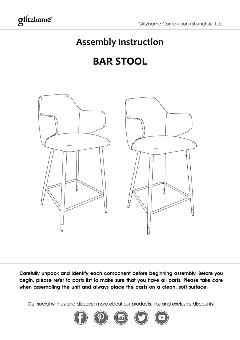
GLITZHOME BAR STOOL User manual

GLITZHOME

GLITZHOME BAR STOOL User manual

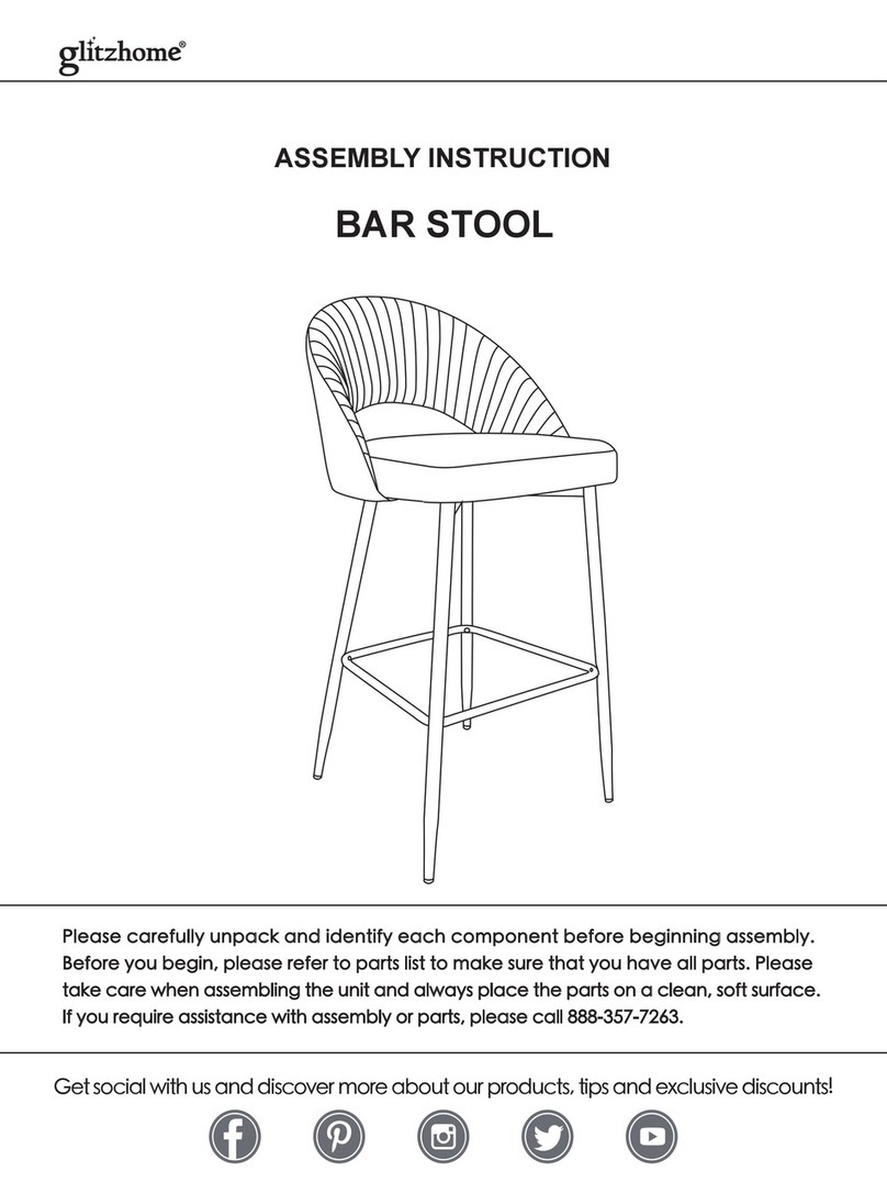
GLITZHOME BAR STOOL User manual

GLITZHOME

GLITZHOME BAR STOOL User manual

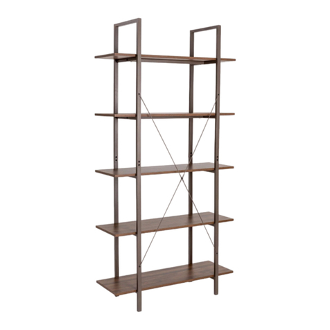
GLITZHOME 2008600015 User manual

GLITZHOME

GLITZHOME 2008600015 User manual

GLITZHOME GH50108 User manual

GLITZHOME

GLITZHOME GH50108 User manual

GLITZHOME 2000800001 User manual

GLITZHOME

GLITZHOME 2000800001 User manual

GLITZHOME OFFICE CHAIR User manual

GLITZHOME

GLITZHOME OFFICE CHAIR User manual

GLITZHOME ACCENT CHAIR 2008600009 User manual

GLITZHOME

GLITZHOME ACCENT CHAIR 2008600009 User manual

GLITZHOME 2000900015 User manual

GLITZHOME

GLITZHOME 2000900015 User manual

GLITZHOME Console Table User manual

GLITZHOME

GLITZHOME Console Table User manual

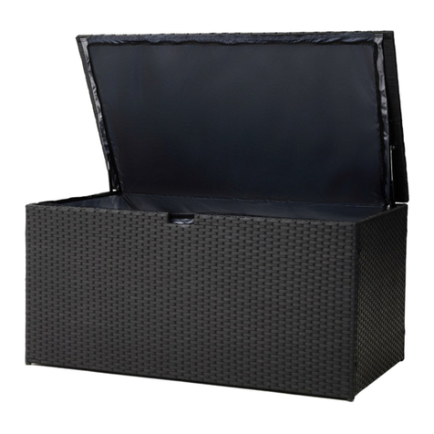
GLITZHOME PATIO WICKER User manual

GLITZHOME

GLITZHOME PATIO WICKER User manual

GLITZHOME Midcentury GH1004202903 User manual

GLITZHOME

GLITZHOME Midcentury GH1004202903 User manual

GLITZHOME OFFICE CHAIR 1009202149 User manual

GLITZHOME

GLITZHOME OFFICE CHAIR 1009202149 User manual

GLITZHOME GH2000600001 User manual

GLITZHOME

GLITZHOME GH2000600001 User manual

GLITZHOME 2001100011 User manual

GLITZHOME

GLITZHOME 2001100011 User manual

GLITZHOME 2000700034 User manual

GLITZHOME

GLITZHOME 2000700034 User manual

GLITZHOME 2000900008 User manual

GLITZHOME

GLITZHOME 2000900008 User manual

GLITZHOME 2000900001 User manual

GLITZHOME

GLITZHOME 2000900001 User manual

GLITZHOME Midcentury GH2001100004 User manual

GLITZHOME

GLITZHOME Midcentury GH2001100004 User manual

GLITZHOME GH1010202516 User manual

GLITZHOME

GLITZHOME GH1010202516 User manual

GLITZHOME GH20169 User manual

GLITZHOME

GLITZHOME GH20169 User manual

GLITZHOME 1005004488 User manual

GLITZHOME

GLITZHOME 1005004488 User manual

GLITZHOME GH50110 User manual

GLITZHOME

GLITZHOME GH50110 User manual

GLITZHOME 2007100007 User manual

GLITZHOME

GLITZHOME 2007100007 User manual

GLITZHOME 5120522 User manual

GLITZHOME

GLITZHOME 5120522 User manual

Popular Indoor Furnishing manuals by other brands

hygena Tall boy 528/9060 Assembly lnstructions

hygena

hygena Tall boy 528/9060 Assembly lnstructions

popstrukt Vienna Side Table Assembly instructions

popstrukt

popstrukt Vienna Side Table Assembly instructions

Mocka Canyon Buffet Assembly instructions

Mocka

Mocka Canyon Buffet Assembly instructions

Costway HU10455-F/Q manual

Costway

Costway HU10455-F/Q manual

Costway HV10180 user manual

Costway

Costway HV10180 user manual

Sunjoy L-DN1196SAL-H-T Assembly instruction

Sunjoy

Sunjoy L-DN1196SAL-H-T Assembly instruction

Kaboodle W-51600 Assembly instructions

Kaboodle

Kaboodle W-51600 Assembly instructions

Article JOKUNA Assembly instructions

Article

Article JOKUNA Assembly instructions

Abbyson Kaylen Assembly instructions & user manual

Abbyson

Abbyson Kaylen Assembly instructions & user manual

GFW POLAR HIGH GLOSS LED TV UNIT Assembly instructions

GFW

GFW POLAR HIGH GLOSS LED TV UNIT Assembly instructions

Z2 Magara MGAK236 Assembling Instruction

Z2

Z2 Magara MGAK236 Assembling Instruction

VINNOVA 703116 manual

VINNOVA

VINNOVA 703116 manual

DIVERSIFIED WOODCRAFTS DT-33A Assembly instructions

DIVERSIFIED WOODCRAFTS

DIVERSIFIED WOODCRAFTS DT-33A Assembly instructions

VonHaus 2500350 instructions

VonHaus

VonHaus 2500350 instructions

FourStarGroup 11224567V Assembly instructions

FourStarGroup

FourStarGroup 11224567V Assembly instructions

interion 695737 Assembly instructions

interion

interion 695737 Assembly instructions

Techni Mobili RTA-988D Assembly instructions

Techni Mobili

Techni Mobili RTA-988D Assembly instructions

Blanco BLANCOMERIDIAN 157-135 Specification sheet

Blanco

Blanco BLANCOMERIDIAN 157-135 Specification sheet

manuals.online logo
manuals.online logoBrands
  • About & Mission
  • Contact us
  • Privacy Policy
  • Terms and Conditions

Copyright 2025 Manuals.Online. All Rights Reserved.