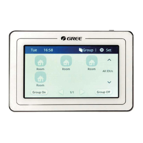
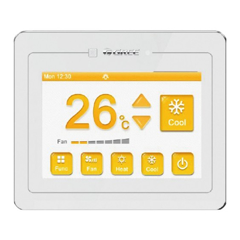
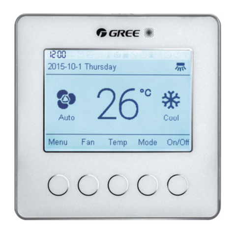
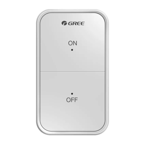
Gree XE70-13/E User manual

Owner's Manual
Original Instructions
Wired Controller XE70-13/E


To Users
Thank you for selecting Gree’s product. Please read this instruction manual
carefully before installing and using the product, so as to master and correctly use the
product. In order to guide you to correctly install and use our product and achieve
expected operating effect, we hereby instruct as below:
(1) This appliance is not intended for use by persons (including children) with
reduced physical, sensory or mental capabilities, or lack of experience and
knowledge, unless they have been given supervision or instruction
concerning use of the appliance by a person responsibility for their safety.
Children should be supervised to ensure that they do not play with the
appliance.
(2) This instruction manual is a universal manual, some functions are only
applicable to particular product. All the illustrations and information in the
instruction manual are only for reference, and control interface should be
subject to actual operation.
(3) In order to make the product better, we will continuously conduct
improvement and innovation. We have the right to make necessary revision
to the product from time to time due to the reason of sales or production,
and reserve the right to revise the contents without further notice.
(4) For personal injury or property loss and damage caused by improper

operation such as improper installation and debugging, unnecessary
maintenance, violation of related national laws and rules and industrial
standard, and violation of this instruction manual, etc., we will bear no
liability.
(5) The final right to interpret for this instruction manual belongs to Gree
Electric Appliances Inc. of Zhuhai.

Contents
1 Safety Notices (Please be sure to abide )..........................1
2 Installation............................................................................2
2.1 Dimension and Component of Wired Controller.................. 2
2.2 Installing Position and Requirements of Wired Controller. 4
2.3 Installation of Wired Controller.............................................. 5
2.4 Disassembly of Wired Controller........................................... 7
3 Display..................................................................................7
3.1 Appearance of Wired Controller............................................. 7
3.2 Home Page Display and Buttons........................................... 8
3.3 Other Icons and Buttons....................................................... 10
4 Functions Description.......................................................11
4.1 Functions Framework ........................................................... 11
4.2 Functions Introduction.......................................................... 12
5 Installation and Debugging...............................................17

6 Operation Instructions ......................................................18
6.1 On/Off...................................................................................... 18
6.2 Mode Setting........................................................................... 20
6.3 Temperature Setting.............................................................. 20
6.4 Fan Setting.............................................................................. 21
6.5 Zone Control........................................................................... 22
6.6 Zone Setting ........................................................................... 24
6.7 Function Setting..................................................................... 29
6.8 View ......................................................................................... 31
6.9 System..................................................................................... 32
6.10 View Malfunction.................................................................. 33

Wired Controller XE70-13/E
1
1 Safety Notices (Please be sure to abide )
WARNING: If not abide strictly, it may cause severe damage to the unit or
the people.
NOTE: If not abide strictly, it may cause slight or medium damage to the
unit or the people.
This sign indicates that the operation must be prohibited. Improper operation
may cause severe damage or death to people.
This sign indicates that the items must be observed. Improper operation
may cause damage to people or property.
WARNING!
This product can’t be installed at corrosive, inflammable or explosive environment
or the place with special requirements, such as kitchen. Otherwise, it will affect the
normal operation or shorten the service life of the unit, or even cause fire hazard or
serious injury. As for above special places, please adopt special air conditioner with
anti-corrosive or anti-explosion function.

Wired Controller XE70-13/E
2
2 Installation
2.1 Dimension and Component of Wired Controller
Figure 2-1 Dimension of Wired Controller (Unit:mm)

Wired Controller XE70-13/E
3
Figure 2-2 Components of Wired Controller
Table 2.1.1 Introduction of Components
No.
①
②
③
④
Name
wired
controller
screw M4×25
installing box
of wired
controller
junction box for
installing inside the wall
Quantity
1
2
1
1(prepared by user)

Wired Controller XE70-13/E
4
2.2 Installing Position and Requirements of Wired
Controller
(1)Please do not install the wired controller in the position where is wet or is
likely to be splashed with water;
(2)Please do not install the wired controller near high-temperature objects or
under direct sunlight;
(3)Before installation, please cut off the power supply of strong current wire
inside the wall, it is not allowed to install under electrified status;
(4)In order to avoid malfunction due to electromagnetic interference and
other causes, please pay attention to the following notices:
1) Make sure that the interface of communication wire is correct, otherwise
the communication cannot work;
2) Signal wire of wired controller should be separated from the power cord
and indoor and outdoor connecting wire, the shortest distance should
be over 20cm, otherwise the communication cannot work normally;
3) If the unit is installed in the position where is likely to be impacted by
electromagnetic interface, signal wire of wired controller should be
made of STP (shielded twisted pair).
(5)The wired controller should only be installed indoors, and its working

Wired Controller XE70-13/E
5
temperature range is 0°C ~50°C .
2.3 Installation of Wired Controller
For installation steps of wired controller please refer to the following sketch map,
brief instructions are as below:
(1)Before installation, please cut off the power supply of indoor unit, live
working during installation is not allowed;
(2)Pull out the STP inside the wall from the installing hole, thread the wire
through the connecting hole in the back of soleplate of wired controller;
(3)Stick the soleplate of wired controller on the wall, use screw M4×25 to fix
the soleplate onto the installing hole of wall;
(4)Connect the four-core terminal of the twisted pairs to the four-pin header
on the wired controller.
(5)Buckle the panel of wired controller with the soleplate, and then the
installation is finished.

Wired Controller XE70-13/E
6

Wired Controller XE70-13/E
7
Figure 2-3 Sketch Map for Installation of Wired Controller
2.4 Disassembly of Wired Controller
Disassembly for wired controller is as below:
Figure 2-4 Sketch Map for Disassembly of Wired Controller
3 Display
3.1 Appearance of Wired Controller

Wired Controller XE70-13/E
8
Fig 3-1 Appearance of Wired Controller
3.2 Home Page Display and Buttons

Wired Controller XE70-13/E
9
Fig 3-2 LCD Display of Wired Controller
Table 3.2.1 Home Page Display and Buttons
No.
Name
Instructions
1
Name of the
current zone
(1)It shows the name of the current zone. The set
temperature displayed on the home page is the
temperature of the current zone.
(2)Tap to switch to another zone.
2
Decrease
Tap to decrease the set temperature of the current zone.
3
Set
temperature
It shows the set temperature of the current zone.
4
Mode
It shows Cool, Dry, Fan, Heat and Auto modes.
5
Button
(1)Press this button to turn on or off the screen.

Wired Controller XE70-13/E
10
(2)Press this button for 5s to reset the screen.
6
Time
(1) It shows the current time.
(2) Press to enter the page of time menu to view or set
the date and time.
7
Increase
Tap to increase the set temperature of the current zone.
8
Zone
Tap to enter the page of zone control to set the name,
temperature, on/off of each effective zone.
9
Fan speed
Tap to change the fan speed.
10
Current fan
speed
It shows the current fan speed.
11
Mode
Tap to switch to another mode.
12
On/Off
Tap to turn on or off the unit.
13
Menu
Tap to enter the page of menu.
14
Home
Tap to turn to the home page.
3.3 Other Icons and Buttons
Table 3.3.1 Other Icons and Buttons
Display
Name
Instructions
Up
(1)Tap to turn to the previous page.
(2)Tap to increase the value.
Down
(1)Tap to turn to the next page.
(2)Tap to decrease the value.

Wired Controller XE70-13/E
11
WiFi
It is shown on the home page, indicating the WiFi
status.
On/Off
(1)Tap to turn on or off the timer function.
(2)Tap to turn on or off the fan valve of a zone.
Enable/Disable
Tap to enable or disable each timer setting.
Return
Tap to return to the previous page.
Zone setting is not
finished.
It is shown on the home page, indicating that zone
setting is not finished yet. Tap to view more
information.
DRED1
DRED2
DRED3
DRED mode
It is shown on the home page, indicating that the
unit is running in DRED mode.
4 Functions Description
4.1 Functions Framework
Basic functions, including fan speed, set temperature, mode, on/off, can be
directly set on the home page. To set other functions or view status of the unit, please
go to the corresponding page. Below is the menu structure.

Wired Controller XE70-13/E
12
Fig 4-1 Menu Structure
4.2 Functions Introduction

Wired Controller XE70-13/E
13
Table 4.2.1 Functions Introduction
Function
Introduction
Daily timer
8 timings can be set independently for each zone. The timer
includes set temperature and zone on/off. It will work every day
after setting.
Week timer
Week timer can be set independently for each zone and 8
timings can be set for each day. The timer includes set
temperature and zone on/off. It will work every week after
setting.
Two week timer
Two week timer can be set independently for each zone and 8
timings can be set for each day. The timer includes set
temperature and zone on/off. It will work every two weeks after
setting.
Zone control
Name, set temperature, and on/off of each zone can be set.
Setting of main
zone
The most frequently used zone can be set as the main zone.
When auto mode is set, the unit’s heating and cooling operation
will be based on the set temperature and ambient temperature
of this zone. This zone must be set.

Wired Controller XE70-13/E
14
Function
Introduction
Setting of always
open zone
When the unit is on, the fan valve of this zone will be open at all
times and cannot be controlled. Temperature setting for this
zone is invalid. This zone must be set.
Setting of zone
parameters
When this product is installed for the first time, zone parameters
must be set so that the zone controller can work normally. Zone
parameters include which zone to be used, the area of the zone,
and whether RF temperature controller is used for the zone.
Connect RF
remote controller
It will send a pairing command to put the zone controller into
pairing mode.
Fresh air function
It can adjust the indoor fresh air volume to improve air quality
and keep the indoor air fresh. (This function works only after
fresh air valve is installed.)
Healthy function
It can generate negative ions. (This function works only after an
applicable device is installed.)
Quiet function
It can lower indoor noise to make the room quiet.
Table of contents
Other Gree Controllers manuals
Popular Controllers manuals by other brands

Riverside Hydronics
Riverside Hydronics TempTrac user manual

WURM
WURM CRC-BL-EEV quick start guide

Siemens
Siemens MVI421 Series Mounting instructions

BIFFI
BIFFI HLRA Installation, operation and maintenance manual

Gewiss
Gewiss Chorus GWA1521 Technical manual

Anaheim Automation
Anaheim Automation MDC151-024031 Series user guide