manuals.online logo
Brands
  1. Home
  2. •
  3. Brands
  4. •
  5. hepco & becker
  6. •
  7. Motorcycle Accessories
  8. •
  9. hepco & becker 5017574 00 01 User manual

hepco & becker 5017574 00 01 User manual

1
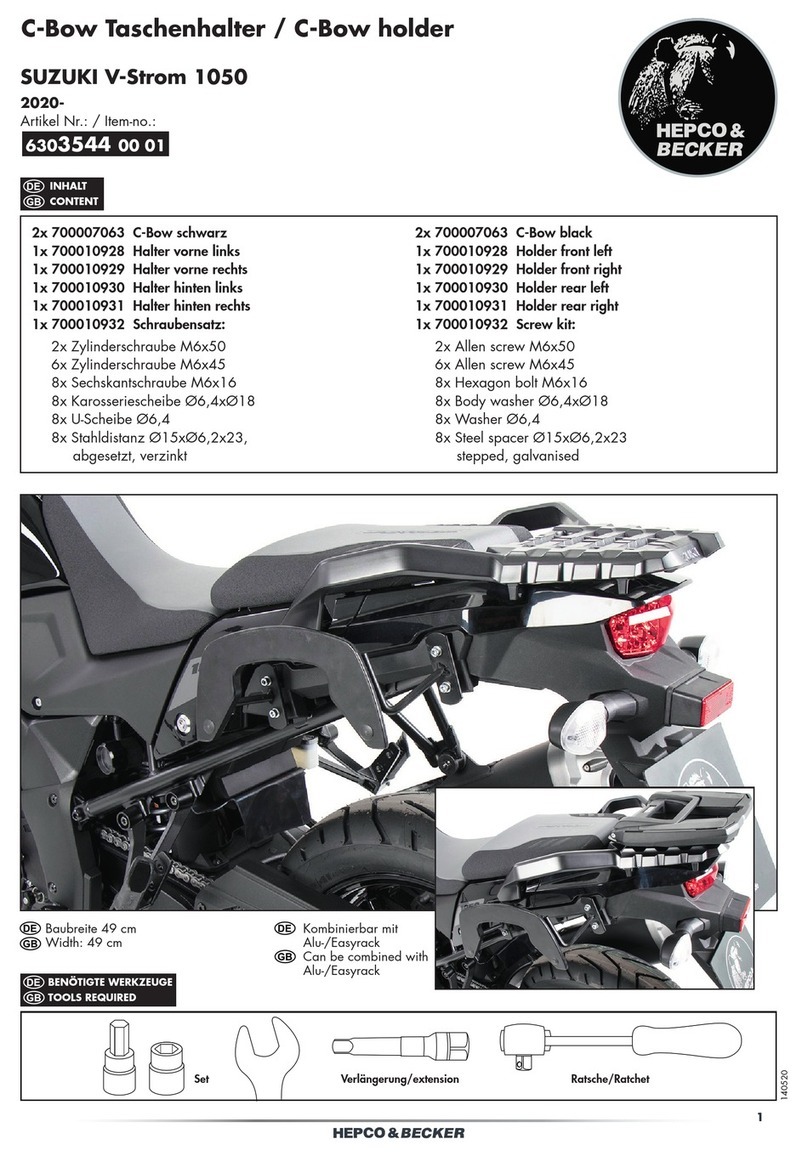
Motorschutzbügel/ Engine guard
DUCATI Scrambler Desert Sled
2017-
Artikel Nr.: / Item-no.:
5017574 00 01 schwarz/black
230218/170620
INHALT
CONTENT
BENÖTIGTE WERKZEUGE
TOOLS REQUIRED
1x 700009907 Motorschutzbügel links
1x 700009908 Motorschutzbügel rechts
1x 700009909 Schraubensatz:
1x 700009907 Engine guard left
1x 700009908 Engine guard right
1x 700009909 Screw kit:
Set Verlängerung/extension Ratsche/Ratchet
1x Halteblech
1x Linsenschraube M10x60
1x Zylinderschraube M12x350
1x Senkkopfschraube M10x65
1x U-Scheibe ø10,5
1x Aludistanz ø25xø11x20
1x Aludistanz ø20xø11x10
2x Aludistanz ø20xø13x10
1x Kunststoffstopfen M12
1x Verbindungsstück Ø25
1x Kabelbinder klein
1x Holding plate
1x Filister head screw M10x60
1x Allen screw M12x350
1x Countersunk screw M10x65
1x Washer ø10,5
1x Alu spacer ø25xø11x20
1x Alu spacer ø20xø11x10
2x Alu spacer ø20xø13x10
1x Plastic plug M12
1x Connector Ø25
1x Cable tie
2
5017574 00 01
WICHTIG
IMPORTANT
Beachten Sie die in Ihrem Land geltenden Zulassungsbestimmungen.
Für den Bereich der BRD gilt: Ein Eintrag in die Fahrzeugpapiere ist nicht erforderlich.
Die Voraussetzung für die Montage ist natürlich eine gewisse technische Erfahrung. Wenn Sie sich nicht sicher sind,wie
man eine bestimmte Arbeit ausführt, sollten Sie diese Ihrer Fachwerkstatt überlassen.
Ziehen sie alle zugänglichen Schrauben zuerst nur locker an. Nachdem alles montiert ist, werden die Schrauben dann auf
das entsprechende Anzugsmoment festgezogen. Dadurch wird sichergestellt, dass das Produkt spannungsfrei angebaut ist.
Anzugsmomente beachten! Nach der Montage alle Verschraubungen auf festen Sitz kontrollieren!
Of course, the assembly requires a certain technical experience. If you are not sure how to execute a determined action,
you should ask your local distributor to do it. First, tighten all screws only loosely. After mounting all parts, the screws
should be tightened to the torque specified. This guarantees, that the product is mounted without tension. Observe
the tightening torques of the manufacturer! Control all screw connections after the assembling for tightness!
VORBEREITUNG
PREPARING
Die Originalschraube der Schaltanlage lösen und diese entfernen.
Anschließend die darüber liegende Schraube entfernen, diese ent-
fällt. Die Originalschraube rechts hinter der Fußhebelbremse sowie
die Originalschraube der oberen Motoraufhängung entfernen, diese
entfallen. Die Aludistanz ø20xø13x10 in die freie Bohrung der obe-
ren Motoraufhängung fügen.
ACHTUNG:
beim Entfernen der Schraube senkt sich der Motorblock ab. Der Motorblock
sollte vorher unterbaut werden, z.B.mit einem Wagenheber.
Zusätzliche Arbeiten für Modell ab 2019:
Vorab das Gestänge des Bremszylinders entfernen, hierfür die Haltek-
lammer lösen. Anschließend den Fußbremshebel und das darunter-
liegende Halteblech des Bremslichtschalters entfernen.
Nun den Schalter vorsichtig demontieren und mit dem Halteblech zu-
sammenfügen, mit dem Kabelbinder sichern.
Remove the original screw of the switchgear and remove it. Then re-
move the screw above, this is obsolete. Remove the original screw on
the righthand side behind the foot lever brake and the original screw
of the upper engine suspension. Insert the alu spacer ø20xø13x10
into the free bore of the upper motor suspension.
DANGER:
When removing the screw the engine block lowers. The engine block should
be underpinned previously, for example, with a jack.
Additional work for model from 2019:
First remove the brake cylinder linkage by loosening the retaining
clip. Then remove the foot brake lever and the holding plate of the
brake light switch underneath.
Now carefully dismantle the switch and join it with the retaining pla-
te, secure with the cable tie.
3
5017574 00 01
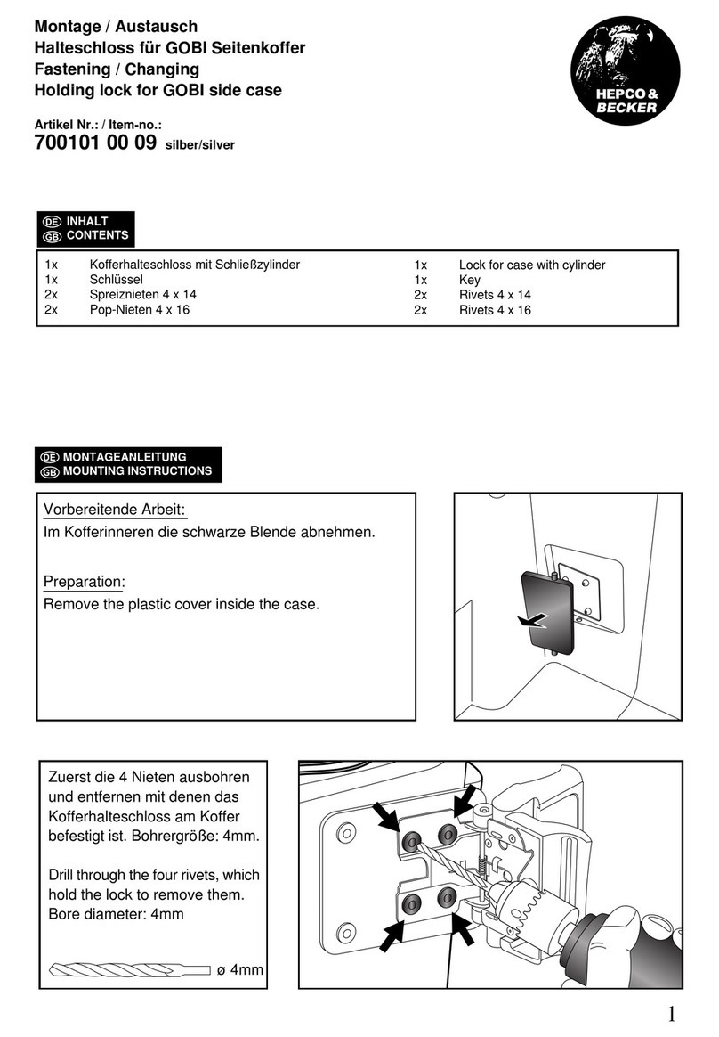
MONTAGEANLEITUNG
MOUNTING INSTRUCTIONS
1
A
1
B
2
1x
1x
1x 1x
1x
1x
Montage Motorschutzbügel rechts unten:
Hinter der Fußhebelbremse mit der
Linsenschraube M10x60 und U-Scheibe
ø10,5. Zwischen Bügel und Rahmen die
Aludistanz Ø25xØ11x20 fügen.
Montage Motorschutzbügel rechts unten:
Zusammen mit dem Halteblech mit der Linsen-
schraube M10x60. Zwischen Rahmen und
Bügel die Aludistanz Ø25xØ11x20 fügen.
Montage Motorschutzbügel rechts oben:
An der Motoraufhängung. Zylinderschraube
M12 x 350 durch Motorschutzbügel und
Aufhängung durchstecken.
Fastening of the engine guard bottom right:
Behind the foot lever brake using the
filister head screw M10x60 and washer
ø10,5. Insert the alu spacer
Ø
25x
Ø
11x20
between the engine guard and the frame.
Fastening of the engine guard bottom right:
Together with the holding plate with filister
head screw M10x60. Insert the alu spacer
Ø25xØ11x20 between frame and bracket.
Fastening of the engine guard top right:
At the engine bolting. Stick the allen screw
M12 x 350 through engine guard and
suspension.
Desert Sled 2017-2018
Desert Sled 2019-
4
3
1x
Zuerst das Verbindungsstück in das offene
Ende des bereits montierten Motorschutzbügels
stecken.
Anschließend den linken Motorschutzbügel auf
das Verbindungsstück aufschieben.
First, plug the connector in the open end of the
already mounted engine guard.
Then slide the left engine guard on the
connector.
5017574 00 01
MONTAGEANLEITUNG
MOUNTING INSTRUCTIONS
4
5
1x
1x
1x
Montage Motorschutzbügel links oben:
An der bereits montierten Schraube M12.
Zwischen Motorschutzbügel und Rahmen die
Aludistanz ø20xø13x10 fügen.
Montage Motorschutzbügel links unten:
Hinter der Schaltanlage mit der Senkkopf-
schraube M10x65. Zwischen Bügel und Rah-
men die Aludistanz ø20xø11x10 fügen.
Fastening of the engine guard top left:
On the pre-assembled M12 screw.
Add alu spacer ø20xø13x10 between the
engine guard and the frame.
Fastening of the engine guard bottom left:
Behind the switchgear with the counter-
sunk screw M10x65. Add the alu spacer
ø20xø11x10 between engine guard and
frame.
5
MONTAGEANLEITUNG
MOUNTING INSTRUCTIONS
Hepco & Becker GmbH
An der Steinmauer 6
D-66955 Pirmasens
Germany
Tel.: +49 (0)6331 - 1453 - 100
Fax: +49 (0)6331 - 1453 - 120
eMail: vertrieb@hepco-becker.de
www.hepco-becker.de
Weiteres Zubehör auf unsere Homepage. More accessories: see our homepage.
ACHTUNG
CAUTION
Nach der Montage alle Verschraubungen auf festen Sitz kontrollieren ! Abgebaute Teile wieder montieren.
Bitte beachten Sie unsere beigefügten Serviceinformationen.
Control all screw connections after the assembling for tightness! Reassemble the dismantled parts.
Please notice our enclosed service information.
5017574 00 01
6
1x
Nach Festziehen aller Schrauben, die Schalt-
anlage wieder montieren und den
Kunststoffstopfen M12 in die Bohrung fügen.
After tightening all screws, reassemble
the switchgear and insert the plastic plug
M12 into the bore M12.

Other hepco & becker Motorcycle Accessories manuals

hepco & becker Easyrack 6619529 01 01 User manual
hepco & becker

hepco & becker Easyrack 6619529 01 01 User manual

hepco & becker 5019526 00 01 User manual

hepco & becker

hepco & becker 5019526 00 01 User manual

hepco & becker 6506525 00 01 Quick start guide

hepco & becker

hepco & becker 6506525 00 01 Quick start guide

hepco & becker 6603545 01 01 User manual

hepco & becker

hepco & becker 6603545 01 01 User manual

hepco & becker 6307546 00 01 User manual

hepco & becker

hepco & becker 6307546 00 01 User manual

hepco & becker 5064564 00 01 User manual

hepco & becker

hepco & becker 5064564 00 01 User manual

hepco & becker 6309514 00 05 User manual

hepco & becker

hepco & becker 6309514 00 05 User manual

hepco & becker Krauser 4005.025.141 User manual

hepco & becker

hepco & becker Krauser 4005.025.141 User manual

hepco & becker 6503534 00 01 User manual

hepco & becker

hepco & becker 6503534 00 01 User manual

hepco & becker 630719 00 02 User manual

hepco & becker

hepco & becker 630719 00 02 User manual

hepco & becker 5013534 00 01 User manual

hepco & becker

hepco & becker 5013534 00 01 User manual

hepco & becker 503998 00 01 User manual

hepco & becker

hepco & becker 503998 00 01 User manual

hepco & becker 8007593 00 01 User manual

hepco & becker

hepco & becker 8007593 00 01 User manual

hepco & becker 630.253 black Installation guide

hepco & becker

hepco & becker 630.253 black Installation guide

hepco & becker 5034543 00 05 User manual

hepco & becker

hepco & becker 5034543 00 05 User manual

hepco & becker 504980 00 05 User manual

hepco & becker

hepco & becker 504980 00 05 User manual

hepco & becker 42167568 00 01 User manual

hepco & becker

hepco & becker 42167568 00 01 User manual

hepco & becker Easyrack User manual

hepco & becker

hepco & becker Easyrack User manual
hepco & becker Sportrack User manual

hepco & becker

hepco & becker Sportrack User manual

hepco & becker 6549523 01 02 User manual

hepco & becker

hepco & becker 6549523 01 02 User manual

hepco & becker 42127581 00 01 User manual

hepco & becker

hepco & becker 42127581 00 01 User manual

hepco & becker 5032545 00 01 User manual

hepco & becker

hepco & becker 5032545 00 01 User manual

hepco & becker 650.779 01 01 Installation guide

hepco & becker

hepco & becker 650.779 01 01 Installation guide

hepco & becker 6614530 01 01 User manual

hepco & becker

hepco & becker 6614530 01 01 User manual

Popular Motorcycle Accessories manuals by other brands

Nolangroup X-lite X-502 Safety and instructions for use

Nolangroup

Nolangroup X-lite X-502 Safety and instructions for use

Youin MA1015 user manual

Youin

Youin MA1015 user manual

PIAGGIO 1D002554 operating instructions

PIAGGIO

PIAGGIO 1D002554 operating instructions

Costway TL27324 user manual

Costway

Costway TL27324 user manual

SHOEI NEOTEC3 393 Instructions for use

SHOEI

SHOEI NEOTEC3 393 Instructions for use

CGM 209 instructions

CGM

CGM 209 instructions

Shad Y0XM20ST manual

Shad

Shad Y0XM20ST manual

KTM 61307908000 Information

KTM

KTM 61307908000 Information

Dynojet Power Commander III installation instructions

Dynojet

Dynojet Power Commander III installation instructions

Alpinestars Stella Tech-Air 3 user guide

Alpinestars

Alpinestars Stella Tech-Air 3 user guide

SRC BMW-F750GS-14-01-SL Installation

SRC

SRC BMW-F750GS-14-01-SL Installation

Shark EvoLine manual

Shark

Shark EvoLine manual

Hogtunes 692Lid-RM Kit installation manual

Hogtunes

Hogtunes 692Lid-RM Kit installation manual

Shark RSF 2 RACE manual

Shark

Shark RSF 2 RACE manual

SW-Motech HPS.08.473.10000/B Mounting instructions

SW-Motech

SW-Motech HPS.08.473.10000/B Mounting instructions

Crivit CASCO JET Instructions for use

Crivit

Crivit CASCO JET Instructions for use

Triumph ACCESORIES 2006 Price list

Triumph

Triumph ACCESORIES 2006 Price list

IBEX 10007163 Mounting instruction

IBEX

IBEX 10007163 Mounting instruction

manuals.online logo
manuals.online logoBrands
  • About & Mission
  • Contact us
  • Privacy Policy
  • Terms and Conditions

Copyright 2025 Manuals.Online. All Rights Reserved.