Hioki 3173 User manual

3173
Instruction Manual
PORTABLE WITHSTANDING
VOLTAGE HiTESTER
EN
Mar. 2019 Revised edition 4
3173A981-04 19-03H


Contents
Introduction i
Inspection i
Safety Notes ii
Notes on Use iv
Chapter Summary v
Chapter 1 Overview 1
1.1 Product Overview 1
1.2 Names and Functions of Parts 2
1.2.1 Front panel 2
1.2.2 Rear panel 4
1.2.3 9615 H.V. TEST LEAD 5
1.3 External Dimensions 6
Chapter 2 Testing Arrangements 7
2.1 Installation of the Unit 7
2.2 Connecting the Protective Ground Terminal 8
2.3 Connecting the External I/O Terminal 9
2.4 Power Cord Connection 10
2.5 Connecting the 9615 H.V. TEST LEAD 11
2.6 Connection to the Measured Equipment 12
2.7 Powering On and Off the 3173 13
2.8 Startup Inspection 14
Chapter 3 Withstand Voltage Testing Method 15
3.1 Starting a Test 16
3.1.1 Setting the Current Threshold Value
(Upper Limit Value) 17
3.1.2 Setting the Timer (Test Time) 18
3.1.3 Setting the Output-voltage 19
3.1.4 Executing a Test 20
3.2 PASS or FAIL Determination 21
3.2.1 "PASS" State 21
3.2.2 "FAIL" State 22
3173A981-04

Chapter 4 External Interface 23
4.1 External I/O Terminal 23
4.1.1 Signal Line 24
4.1.2 Timing Chart of External I/O Terminal 26
4.2 Example of External I/O Terminal 28
4.2.1 Example of Input Signal Connection 28
4.2.2 Example of Output Signal Connection 30
Chapter 5 Specifications 33
5.1 Basic Specifications 33
5.2 General Specifications 35
5.3 9615 H.V. TEST LEAD Specifications 36
Chapter 6 Maintenance and Servise 37
6.1 Maintenance and Inspection 37
6.2 Cleaning 38
6.3 Fuse Replacement 39

i
_____________________________________________________________________________________________
______________________________________________________________________________________________
WARNING
Before using the product, make sure that the insulation on the test
leads is undamaged and that no bare conductors are improperly
exposed. Using the product under such conditions could result in
electrocution. Replace the test leads specified by Hioki .
Introduction
Inspection
Thank you for purchasing the HIOKI 3173 PORTABLE WITHSTANDING
VOLTAGE HiTESTER. To obtain maximum performance from the product,
please read this manual first, and keep it handy for future reference.
Warranty
HIOKI cannot be responsible for losses caused either directly or indirectly by
the use of the 3173 with other equipment, or if ownership is transferred to a
third party.
When you receive the product, inspect it carefully to ensure that no damage
occurred during shipping. In particular, check the connectors and
accessories. If damage is evident, or if it fails to operate according to the
specifications, contact your dealer or Hioki representative.
Accessories
9615 H.V.TEST LEAD (HIGH/LOW) 1 each
Power cord 1
Spare fuse 1
Instruction Manual 1
Preliminary Checks
Before using the product the first time, verify that it operates normally to
ensure that the no damage occurred during storage or shipping. If you find
any damage, contact your dealer or Hioki representative.
Use the original packing materials when reshipping the product, if possible.

ii
_____________________________________________________________________________________________
______________________________________________________________________________________________
WARNING
This product is designed to conform to IEC 61010 Safety Standards, and
has been thoroughly tested for safety prior to shipment. However,
mishandling during use could result in injury or death, as well as
damage to the product. Be certain that you understand the instructions
and precautions in the manual before use. We disclaim any
responsibility for accidents or injuries not resulting directly from
product defects.
The symbol printed on the product indicates that the user should
refer to a corresponding topic in the manual (marked with the
symbol) before using the relevant function.
In the manual, the symbol indicates particularly important
information that the user should read before using the product.
Indicates that dangerous voltage may be present at this terminal.
Indicates AC (Alternating Current).
Indicates a fuse.
Indicates a protective conductor terminal.
Indicates the ON side of the power switch.
Indicates the OFF side of the power switch.
DANGER
Indicates that incorrect operation presents an extreme hazard that
could result in serious injury or death to the user.
WARNING
Indicates that incorrect operation presents a significant hazard that
could result in serious injury or death to the user.
CAUTION Indicates that incorrect operation presents a possibility of injury to
the user or damage to the product.
NOTE Advisory items related to performance or correct operation of the
product.
Safety Notes
This manual contains information and warnings essential for safe operation
of the product and for maintaining it in safe operating condition. Before
using the product, be sure to carefully read the following safety notes.
Safety Symbols
The following symbols in this manual indicate the relative importance of
cautions and warnings.

iii
_____________________________________________________________________________________________
______________________________________________________________________________________________
WARNING
Using a measuring instrument in an environment designated with a
higher-numbered category than that for which the instrumen is rated
could result in a severe accident, and must be carefully avoided.
Never use a measuring instrument that lacks category labeling in a
CAT II to CAT IV measurement environment. Doing so could result in
a serious accident.
CAT II When directly measuring the electrical outlet receptacles of the
primary electrical circuits in equipment connected to an AC
electrical outlet by a power cord (portable tools, household
appliances, etc.)
CAT III When measuring the primary electrical circuits of heavy equipment (fixed
installations) connected directly to the distribution panel, and feeders
from the distribution panel to outlets
CAT IV When measuring the circuit from the service drop to the service entrance,
and to the power meter and primary overcurrent protection device
(distribution panel)
f.s. (maximum display value or scale length)
The maximum displayable value or the full length of the scale.
This is usually the maximum value of the currently selected range.
rdg. (reading or displayed value)
The value currently being measured and indicated on the measuring
product.
Measurement categories
To ensure safe operation of measuring instruments, IEC 61010 establishes
safety standards for various electrical environments, categorized as CAT II to
CAT IV, and called measurement categories.
Accuracy We define measurement tolerances in terms of f.s. (full scale) and rdg.
(reading) values, with the following meanings:

iv
_____________________________________________________________________________________________
______________________________________________________________________________________________
DANGER
Observe the following precautions to avoid electric shock.
Do not remove the product's case. The internal components of the
product carry high voltages and may become very hot during
operation.
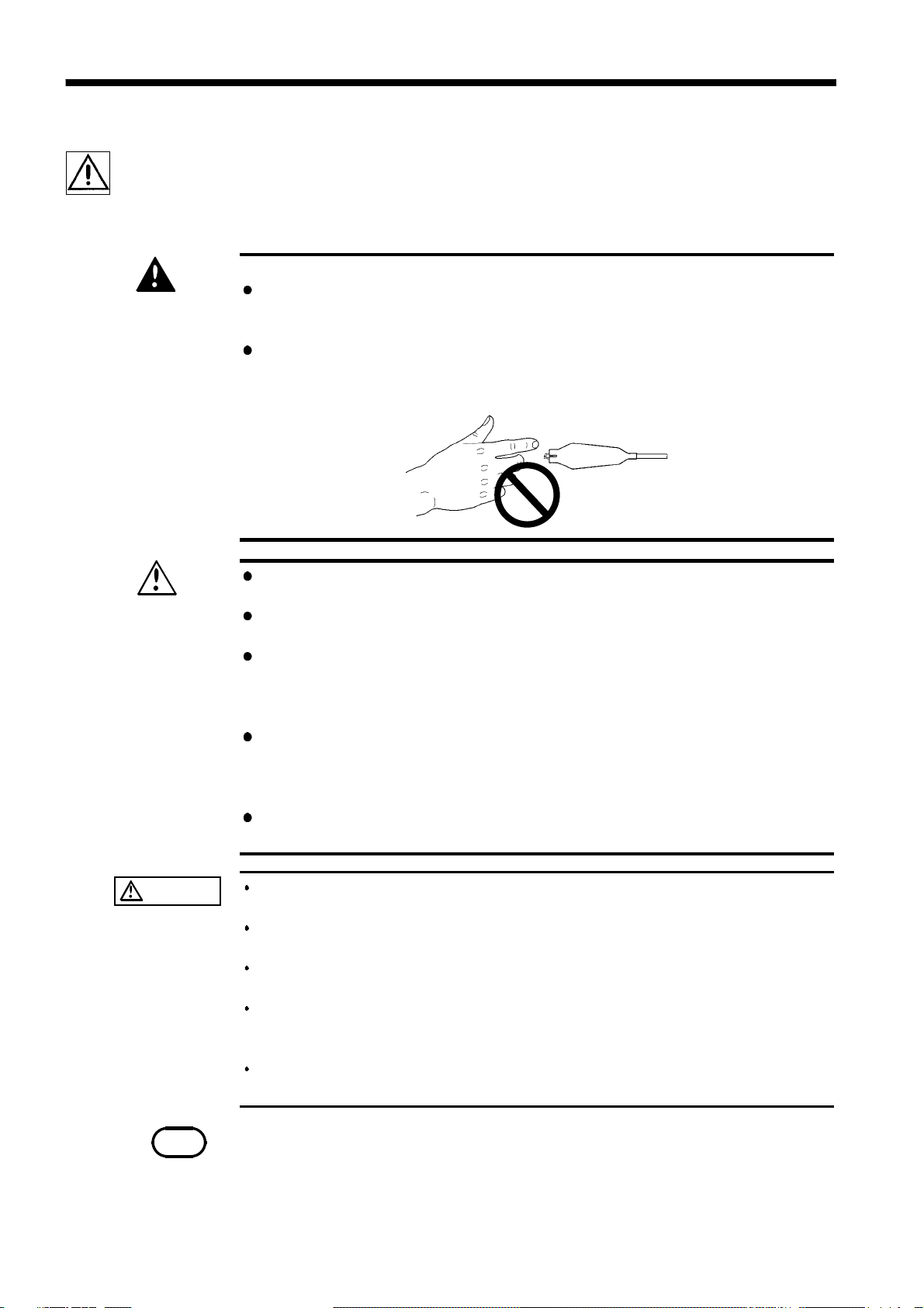
Do not touch the alligator clip while high voltage is being generated.
The vinyl sheath on the alligator clip of the 9615 H.V.TEST LEAD does
not have an insulation withstand voltage.
WARNING
To avoid electric shock, do not allow the product to get wet, and do
not use it when your hands are wet.
To avoid electric shock, connect the protective ground terminal to a
grounded conductor before making any other connections.
Before turning the product on, make sure the source voltage matches
that indicated on the product's power connector. Connection to an
improper supply voltage may damage the product and present an
electrical hazard.
Replace the fuse only with one of the specified characteristics and
voltage and current ratings. Using a non-specified fuse or shorting the
fuse holder may cause a life-threatening hazard.
Fuse type: 250VT1AL (3173, 3173-01), 250VT0.5AL (3173-02, 3173-03, 3173-04)
To avoid electrocution, turn off the power to all devices before
pluggingor unplugging any of the interface connectors.
CAUTION To avoid damaging the power cord, grasp the plug, not the cord, when
unplugging the cord from the power outlet.
To avoid damaging the test leads, do not bend or pull the 9615 H.V. TEST
LEADs.
To avoid damage to the product, protect it from vibration or shock during
transport and handling, and be especially careful to avoid dropping.
Do not use the product near a device that generates a strong
electromagnetic field or electrostatic charge, as these may cause
erroneous measurements.
To avoid electric shock, do not exceed the lower of the ratings shown on
the instrument and test leads.
NOTE This product may cause interference if used in residential areas. Such use must be
avoided unless the user takes special measures to reduce electromagnetic emissions
to
p
revent interference to the rece
p
tion of radio and television broadcasts.
Notes on Use
Follow these precautions to ensure safe operation and to obtain the full
benefits of the various functions.

v
_____________________________________________________________________________________________
______________________________________________________________________________________________
Chapter Summary
Chapter 1 Overview
Describes an overview, features, and the names and functions of the parts of
the product.
Chapter 2 Testing Arrangements
Describes particulars of testing arrangements.
Chapter 3 Testing Method
Describes procedures for setting, testing, and test results judgment.
Chapter 4 External Interface
Describes use of the external I/O terminal.
Chapter 5 Specifications
Describes the product specifications.
Chapter 6 Maintenance and Servise
Describes the maintenance and inspection, fuse replacement, and ultimate
disposal.

vi
_____________________________________________________________________________________________
______________________________________________________________________________________________

1
_____________________________________________________________________________________________
1.1 Product Overview
______________________________________________________________________________________________
Chapter 1
Overview
1.1 Product Overview
(1) Simple design with a streamlined set of core functions.
Simple, clean design with a streamlined set of essential functions - highly
portable and perfectly suited to inspections on the production line.
(2) Test timer
The test timer can set test times between 1 and 99 seconds in increments of
1 second.
(3) Analog voltmeter
The test voltage is monitored using the analog voltmeter.
(4) External I/O
The tester has external I/O terminals on its rear panel, which are used to
output various status signals and to input test start and stop signals.

2
_____________________________________________________________________________________________
1.2 Names and Functions of Parts
______________________________________________________________________________________________
1.2.1 Front panel
WARNING
To avoid electric shock, never touch the output-voltage terminals (HIGH
and LOW), high-voltage test leads or the device being tested while high
voltage is being applied.
Analog voltmeter
Test timer LED
Current threshold
setting dial
Test timer
setting dial
Test timer switch
DANGER lamp
HIGH terminal
LOW terminal
START key
STOP key
Output-voltage
adjustment knob
Power LED
Power switch
Test result LED
1.2 Names and Functions of Parts

3
_____________________________________________________________________________________________
1.2 Names and Functions of Parts
______________________________________________________________________________________________
Analog voltmeter Indicates output-voltage when testing withstand voltage.
Test timer LED The LED lights up during testing when the timer is set to
ON.
Current threshold setting dial Sets the current threshold.
(0.1 to 9.9 mA, resolution of 0.1 mA)
Test timer setting dial Sets the timer (test time). (1 to 99 s, resolution of 1 s)
Test timer switch Turns ON/OFF the test timer.
DANGER lamp This lamp lights to warn that voltage is present between the
terminals during testing.
HIGH terminal The HIGH terminal is a high-voltage terminal for voltage
outputs.
LOW terminal The LOW terminal is a low-voltage terminal for voltage
outputs. It has the same electric potential as the unit body.
Output-voltage adjustment
knob Sets the output-voltage.
Test result LED One of the two LEDs will light, depending on the test result.
START key Used to start a test.
STOP key Normally used to terminate a test.
Power switch Powers the 3173 on or off.
The LED lights up when power is turned ON.

4
_____________________________________________________________________________________________
1.2 Names and Functions of Parts
______________________________________________________________________________________________
1.2.2 Rear panel
WARNING
To avoid electric shock, never touch the output-voltage terminals (HIGH
and LOW), high-voltage test leads or the device being tested while high
voltage is being applied.
Fuse holder
External I/O terminal
Power inlet
Protective ground
terminal
Fuse holder Contains a power fuse.
External I/O terminal Each signal is output by ON/OFF of the relay depending on the test
result. Terminals for start and stop input signals are also available.
Power inlet Connect the grounded three-core power cord supplied here.
Protective ground
terminal Used to earth a protective ground wire. Be sure to make grounding
connections before starting a test.

5
_____________________________________________________________________________________________
1.2 Names and Functions of Parts
______________________________________________________________________________________________
1.2.3 9615 H.V. TEST LEAD
DANGER
To avoid electric shock, do not touch the alligator clip while high
voltage is being generated. The vinyl sheath on the alligator clip of the
9615 H.V.TEST LEAD does not have an insulation withstand voltage.
1
2
3
1
High-voltage side (red)
Low-voltage side (black)
1Alligator clip Attach to the test point on the device being measured.
2High-voltage output
plug Connect to the HIGH terminal on the unit.
3Low-voltage output
plug Connect to the LOW terminal on the unit.

6
_____________________________________________________________________________________________
1.3 External Dimensions
______________________________________________________________________________________________
200 2mm
7.87 0.08"
149 2mm
5.87 0.08"
215 2mm
8.46 0.08"
1.3 External Dimensions

7
_____________________________________________________________________________________________
2.1 Installation of the Unit
______________________________________________________________________________________________
NOTE The noise generated by this unit may affect equipment located around the unit.
Chapter 2
Testing Arrangements
2.1 Installation of the Unit
Temperature: 0 to 40 (32 to 104 )
Humidity: 80% RH or less (no condensation)
Do not place the tester upside down. Be sure to place the tester with
its bottom side down.
Avoid the following locations:
・Subject to direct sunlight.
・Having poor air circulation.
・Subject to high levels of dust, steam, or corrosive gases (Avoid
using the equipment in an environment containing corrosive gases
(e.g., H2S, SO2,NI
2,andCI
2) or substances that generate harmful
gasses (e.g., organic silicones, cyanides, and formalins)).
・Subject to vibrations.
・In the vicinity of equipment generating strong electromagnetic
fields.

8
_____________________________________________________________________________________________
2.2 Connecting the Protective Ground Terminal
______________________________________________________________________________________________
WARNING
To avoid electric shock, be sure to connect the protective ground
terminal to a grounded conductor.
To avoid electric shock, connect the protective ground terminal to a
grounded conductor before making any other connections.
2.2 Connecting the Protective Ground Terminal
1. Using a Phillips-head screwdriver, remove the screw of the protective
ground terminal from the rear of the unit.
2. Connect an electric wire with a sufficient current capacity to the
protective ground terminal, and secure the wire using a Phillips-head
screwdriver.
3. Ground the other end of the wire.

9
_____________________________________________________________________________________________
2.3 Connecting the External I/O Terminal
______________________________________________________________________________________________
NOTE For the specifications of the external I/O terminal, see Section 4.1.
2.3 Connecting the External I/O Terminal
Connect the external I/O terminal before turning on the power. If the external
I/O terminal is installed or removed following startup, malfunction may
result.
1. Press and hold the button on the terminal block using a flathead
screwdriver.
2. While holding the button, insert a signal cable with insulation removed
from the end into the hole.
3. Release the button to secure the cable to the terminal.

10
_____________________________________________________________________________________________
2.4 Power Cord Connection
______________________________________________________________________________________________
WARNING
Before turning the product on, make sure the source voltage matches
that indicated on the product's power connector. Connection to an
improper supply voltage may damage the product and present an
electrical hazard.
Supply voltage indicated on the rear panel
2.4 Power Cord Connection
1. Be sure that the power switch is turned to OFF.
2. Connect the grounded three-core power cord provided to the power inlet
on the back of the unit.
3. Insert the plug into the grounded outlet.
Table of contents
Other Hioki Test Equipment manuals