Warranty
Warranty malfunctions occurring under conditions of normal use in con-
formity with the Instruction Manual and Product Precautionary Mark-
ings will be repaired free of charge. This warranty is valid for a period
of one (1) year from the date of purchase. Please contact the distribu-
tor from which you purchased the product for further information on
warranty provisions.
Introduction
Thank you for purchasing the HIOKI Model
3291-50 CLAMP ON
HiTESTER. To obtain maximum performance from the instrument,
pleasereadthismanualfirst,andkeepit handy forfuture reference.
Because it employs a small, thin-type sensor the 3291-50 Clamp On
HiTester can clamp even in narrow places. In addition, the angle of
the display panel can be changed to suit the measuring location and
the back light makes the instrument easy to use even in dark places.
Initial Inspection
When you receive the instrument, inspect it carefully to ensure
that no damage occurred during shipping. If damage is evident,
or if it fails to operate according to the specifications, contact
your dealer or Hioki representative.
• To clean the instrument, wipe it gently with a soft cloth moist-
ened with water or mild detergent. Never use solvents such
as benzene, alcohol, acetone, ether, ketones, thinners or
gasoline, as they can deform and discolor the case.
• If the protective functions of the instrument are damaged, either
remove it from service or mark it clearly so that others do not
use it inadvertently.
• If the instrument seems to be malfunctioning, contact your
dealer or Hioki representative.
This manual contains information and warnings essential for
safeoperationof the instrumentand formaintainingitin safeop-
erating condition. Before using it, be sure to carefully read the
following safety precautions.
Safety Symbol
Notation of the This Manual
Symbols for Various Standards
The following symbols in this manual indicate the relative importance
of cautions and warnings.
Measurement categories
To ensure safe operation of measuring instruments, IEC 61010 estab-
lishes safety standards for various electrical environments, categorized
as CAT II to CAT IV, and called measurement categories.
This instrument complies with CAT III 600 V, CAT IV 300 V safety re-
quirements.
CAT II:When directly measuring the electrical outlet receptacles of the
primary electrical circuits in equipment connected to an AC
electrical outlet by a power cord (portable tools, household ap-
pliances, etc.)
CAT III:When measuring the primary electrical circuits of heavy equip-
ment (fixed installations) connected directly to the distribution
panel, and feeders from the distribution panel to outlets
CAT IV:When measuring the circuit from the service drop to the service
entrance, and to the power meter and primary overcurrent pro-
tection device (distribution panel)
Follow these precautions to ensure safe operation and to obtain
the full benefits of the various functions.
Measurement specification
• Temperature and humidity for guaranteed accuracy: 23±5°C
(73±9°F), 80%RH or less.
• Guaranteed accuracy period: 1 year, opening and closing of
the jaws 10,000 times, whichever comes first.
• Guaranteed accuracy range: 2.00 A or above
AC current A rms (true rms indication, Auto range)
Zero-display range: 0.30 A or less
We define measurement tolerances in termsof rdg. (reading) and dgt. (digit) val-
ues, with the following meanings:
rdg. (reading or displayed value)
The value currently being measured and indicated on the measuring instrument.
dgt. (resolution)
The smallest displayable unit on a digital measuring instrument, i.e., the input
value that causes the digital display to show a "1" as the least-significant digit.
General Specifications
Functions
Overview
Inspection
Maintenance and Service
3291-50
CLAMP ON HiTESTER
Instruction Manual
Aug. 2016 Revised edition 6
Printed in Japan
3291C981-06 16-08H
EN
Safety
This instrument is designed to comply with IEC 61010 Safety
Standards, and has been thoroughly tested for safety prior to
shipment. However, mishandling during use could result in
injury or death, as well as damage to the instrument. However,
using the instrument in a way not described in this manual may
negate the provided safety features. Be certain that you under-
stand the instructions and precautions in the manual before
use. We disclaim any responsibility for accidents or injuries not
resulting directly from instrument defects.
Indicates cautions and hazards. When the symbol is printed on
the instrument, refer to a corresponding topic in the Instruction
Manual.
Indicates AC (Alternating Current).
Indicates DC (Direct Current).
Indicates that the instrument may be connected to or discon-
nected from a live circuit.
Indicates a double-insulated device.
Indicates a prohibited action.
This symbol indicates that the instrument conforms to regulations
set out by the EC Directive.
Indicates the Waste Electrical and Electronic Equipment Directive
(WEEE Directive) in EU member states.
Indicates that incorrect operation presents an extreme hazard
that could result in serious injury or death to the user.
Indicates that incorrect operation presents a significant hazard
that could result in serious injury or death to the user.
Indicates that incorrect operation presents a possibility of
injury to the user or damage to the device.
Indicates advisory items related to performance or correct
operation of the instrument.
• Using a measuring instrument in an environment designated
with a higher-numbered category than that for which the
instrument is rated could result in a severe accident, and
must be carefully avoided.
• Using a measuring instrument without categories in an envi-
ronment designated with the CAT II to CAT IV category could
result in a severe accident, and must be carefully avoided.
Usage Notes
Do not allow the instrument to get wet, and do not take
measurements with wet hands. This may cause an elec-
tric shock.
• Do not store or use the instrument where it could be exposed
to direct sunlight, high temperature or humidity, or conden-
sation. Under such conditions, the instrument may be dam-
aged and insulation may deteriorate so that it no longer
meets specifications.
• This instrument contains a magnetic core. The device
should not be used by anyone with apacemaker or any other
electronic medical devices installed in his body.
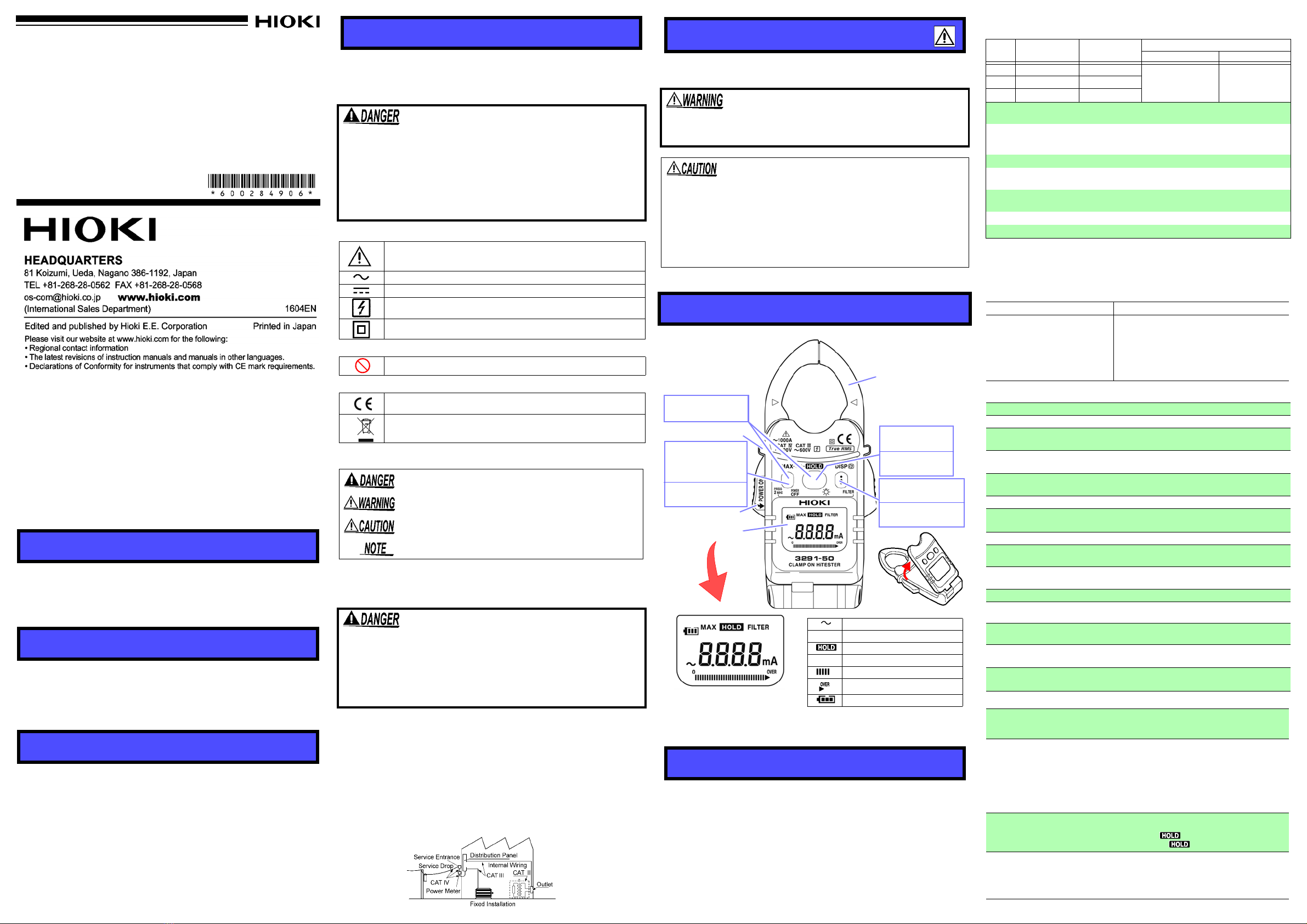
Names and Functions of Parts
Specifications
Alternating current (AC)
MAX MAX value
Data hold function
FILTER Filter ON
Bar graph
Over range
Battery low warning (4 levels)
Jaws
Barrier
Lever
Display (LCD)
Press once
Press 2 sec.
Digital display
Filter OFF/ON
Press once
Press 2 sec.
Maximum data
Power OFF
(Magnified View)
* The device considers the maximum
displayed value to be the MAX value.
Press once
Press 2 sec.
Data hold
Back light
Press both
Clear MAX value
Instantaneous
value
Range Guaranteed
accuracy Minimum
resolution Accuracy
FILTER OFF FILTER ON
60 A 2.00 A to 60.00 A 0.01 A ±1.5%rdg.±5dgt.
(45 Hz to 66 Hz)
±3%rdg.±5dgt.
(66 Hz to 400 Hz)
±1.5% rdg. ±5dgt.
(50 Hz to 60 Hz)
600 A 54.0 A to 600.0 A 0.1 A
1000 A 540 A to1000 A 1 A
Effect of conductor
position Within±5.0% (in any position based on the center of
the jaws)
Maximum rated
voltage to earth 600 Vrms
Measurement category III (anticipated
transient overvoltage 6000 V),
300 Vrms
Measurement
category
IV
(anticipated transient overvoltage 6000 V)
Crest factor
2.8 or less (up to 600 A), 1.68 or less (1000 A range)
Diameter of
measurable conductor
30 mm dia. or less
Temperature
characteristics Add measurement accuracy × 0.05 / °C
(except 23°C±5°C (73°F±9°F))
Response time
1.
1 sec. or less
Maximum input current
1000 A continuous
Example Calculation
Accuracy spec.
Measurement range
Measurement values
:±1.5%rdg. ±5dgt.
:60.00 A
:30.00 A
(A)
(B)
(C)
Reading error (± %rdg.):± 1.5% of 30.00 A =
± 0.45 A
Digit error (± dgt.):± 5dgt. =± 0.05 A (Due to
minimum resolution of 0.01 A)
Total error: (A)+(B) = ± 0.50 A
The limit error value for the measured value of
30.00 A is 29.50 A ~30.50 A based on the total
error (C).
Display update rate 1.1 sec. or less
Display LCD: monochrome, 91 segments
Operating temperature
and humidity
0 to 40°C (32 to 104°F), 80%RH or less
(with no condensation)
Storage temperature
and humidity -10 to 50°C
(14.0 to 122.0°F), 80%RH or less
(
with no condensation
)
Location for use indoors,
Pollution degree 2,
Altitude up to 2000 m (6562 feet)
Rated supply voltage 3 VDC
Maximum rated
power 25 mVA
Power supply CR2032 x 1 Lithium battery
Battery lifetime Approx.20 hours
(continuous, no load, at 23°C)
Dimensions Approx. 50 W × 136 H × 26 D mm (1.97”W×5.35”H×1.02”D)
(Without protrusions)
Mass Approx. 115 g (4.1 oz.)
Dielectric strength
7060 Vrms /1 minute, 1 mA sensitivity current
between the jaws and case
Applicable standards
Safety EN61010
EMC EN61326
Accessories 9757 Carrying case, Strap, Instruction manual,
CR2032 Lithium battery
Product warranty
period 1 year
Power supply control ON: Grasping the lever and opening wide the jaws
(sideways).
OFF: Press POWER OFF key for 2 seconds or longer.
Filter
Details of operation
: Low pass filter ON/OFF
Cutoff frequency:180 Hz±30 Hz (-3dB)
Initial setting: OFF (Always OFF when the power supply
is turned on; non-filtered data is not saved)
Activate/De-activate: Press FILTER key for 2 seconds or
longer.
*When set to ON, the filter removes noise and other
unwanted frequency components.
Data hold Details of operation: Holds measured values
(data update is halted)
Activate:
Pressing the key once.
De-activate:Pressing the key once. Filter ON/OFF
MAX value display
Details of operation: Displays the maximum measured
values reached since the power has been turned on.
Activate/De-activate: Pressing the MAX key once.
Clear displayed maximum value: Press MAX key and
HOLD key at the same time.
Filter ON/OFF


