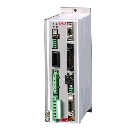
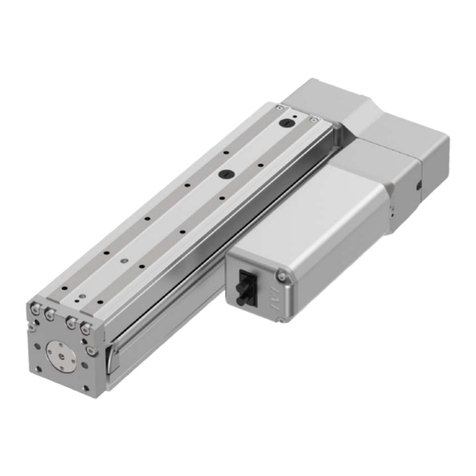
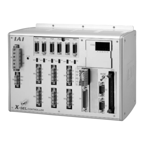
IAI ASEP User manual

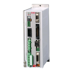
ASEP Controller
PSEP Controller
IAI America Inc.
Operation Manual Fourth Edition


Introduction
Thank you for purchasing our product.
This Operation Manual describes all necessary information items to operate this product safely such
as the operation procedure, structure and maintenance procedure.
Before the operation, read this manual carefully and fully understand it to operate this product safely.
The enclosed CD in this product package includes the Operation Manual for this product.
For the operation of this product, print out the necessary sections in the Operation Manual or display
them using the personal computer.
After reading through this manual, keep this Operation Manual at hand so that the operator of this
product can read it whenever necessary.
Important Information
yFor any result of any operation not described in this Operation Manual, we do not have any
responsibility. Please understand it.
yThe contents of this Operation Manual are subject to change for improvement without prior
notice.
yIn the case that you have any question or doubt in the contents of this Operation Manual,
contact “IAI Customer Center Eight” or the nearest IAI sales office.
yThis Operation Manual shall not be used or copied, in whole or part, without our written
consent.


Contents
Safety Guide............................................................................................................ 1
Precautions in Operation ......................................................................................... 9
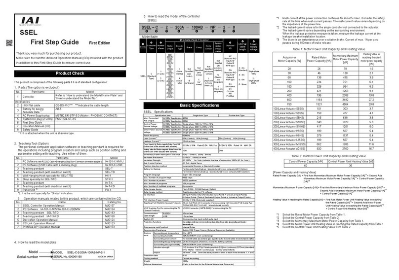
1. Product Check ................................................................................................... 15
1.1 Parts (The option is excluded.)................................................................................................... 15
1.2 Teaching Tool (Option) .......................................................................................................15
1.3 Operation manuals related to this product,
which are contained in the operation manual (CD)......................................................16
1.4 How to read the model plate ..............................................................................................16
1.5 How to read the model of the controller .............................................................................16
2. Basic Specifications............................................................................................17
3. External Dimensions.......................................................................................... 19
4. Installation Environment..................................................................................... 20
5. Installation and Noise Eliminati .......................................................................... 21
5.1 Noise Elimination Grounding (Frame Ground) ...................................................................21
5.2 Precautions regarding wiring method ................................................................................21
5.3 Noise Sources and Elimination ..........................................................................................21
5.4 Heat Radiation and Installation ..........................................................................................22
6. Wiring ................................................................................................................ 23
7. LED indication.................................................................................................... 24
8. Power Connector ............................................................................................... 25
9. PIO Connector ................................................................................................... 26
10. Setting.............................................................................................................. 33
11. Timing Chart..................................................................................................... 37
12. Starting Procedures ..........................................................................................41
13. User Parame.................................................................................................... 42
14. Alarm Codes and Trouble Shooting ................................................................. 44
15. Appendix.......................................................................................................... 48
16. Warranty Period and Scope of Warranty ......................................................... 49


1
Laws and Standards for the Industrial Robots
For the safety measures for the mechanical system, generally the following four measures are
specified based on the International Industrial Standards ISO/DIS12100 “Safety for Machinery”.
Based on the above, various standards are specified for each level in the International Standards
ISO/IEC. The safety standards for the industrial robots are as follows.
The domestic laws for the safety of the industrial robots are established as follows.
Article 59 in the Industrial Safety and Health Law
The practice of special training is obliged for the labors who are engaged in dangerous or
harmful jobs.
Ordinance on Industrial Safety and Hygiene
Article 36·············Jobs that require the special training
No. 31 (Teaching, etc.) ···············For the teaching operation, etc., for the industrial
robots (with some exceptions)
No. 32 (Inspection, etc.) ·············For the inspection, repair or adjustment operation,
etc., for the industrial robots (with some exceptions).
Article 150···········For the measures to be taken by the user of the industrial robot
Safety
Measures Essential Safety Design
Safety Protection································· Safety Fence, etc.
Additional Safety Measures ················ Emergency Stop Device, etc.
Information in Use ······························· Alarm Indication, Warning,
Operation Manual
Type C Standards
(Individual Safety
Standards)
ISO10218 (Manipulating Industrial Robots - Safety)
JIS B 8433
(Industrial Manipulating Robots - Safety)
Safety Guide
“Safety Guide” has been written to use the machine safely and so prevent personal injury or
property damage beforehand. Make sure to read it before the operation of this product.

2
Operation
Area
Operation
Condition
Interruption of
Driving Source Treatment Specified in
Signal for operation startup Article 104Out of
Moving
Range
In Automatic
Operation Disable Fence or enclosure
installation, etc.
Item 4 in
Article 150
Enable
(Including
Operation Stop)
Indication showing “Under
Operation”
Item 3 in
Article 150
Preparation of Stipulations for
the Operation
Item 3 in
Article 150
Treatment to stop the
operation immediately
Item 3 in
Article 150
Indication showing “Under
Operation”
Item 3 in
Article 150
Practice of special training No. 31 in
Article 36
In Operation
such as
Teaching Disable
Checks, etc., before
operation startup Article 151
Performing it with the
machine stopped.
Item 5 in
Article 150
Enable Indication showing “Under
Operation”
Item 5 in
Article 150
Preparation of Stipulations for
the Operation
Item 5 in
Article 150
Treatment to stop the
operation immediately
Item 5 in
Article 150
Indication showing “Under
Operation”
Item 5 in
Article 150
Within the
Moving
Range
In Operation
such as
Inspection
Disable
(In the case that
it is performed
unavoidably
during the
machine
operation)
Practice of special training
(Excluding the cleaning and
oiling operations)
No. 32 in
Article 36
Requirements for the Industrial Robots set forth in the Ordinance on
Industrial Safety and Hygiene

3
Our Models regarded as Industrial Robots
The products which come under the following conditions, are excluded from the Industrial Robot
category according to the notice from the Ministry of Labor and the notification issued by the
director general of the Labor Standards Bureau in the Ministry of Labor (No. 340).
(1) Single-axis robot product with the motor wattage of 80W or less
(2) Multi-combined shaft robot product with the length of X, Y, and Z-axis of 300 mm or less and, if
there is any rotary section, the maximum movable range is 300 cubic mm or less including the
end section of the rotary section.
(3) Articulated robot product with both the movable radius and the length of Z-axis of 300 mm or
less.
Our models regarded as the industrial robots among the products in our catalogue are as follows.
1. Single Axis ROBO CYLINDER
RCS2/RCS2CR-SS8 with the stroke exceeding 300 mm
2. Single Axis Robot
Following models with the stroke exceeding 300 mm and motor capacity exceeding 80W
ISPDA, ISWA/ISPWA, IF, FS, NS
3. Linear Servo-Actuator
All the models with the stroke exceeding 300 mm
4. Cartesian-Type Robot
Any of the models in Item 1 through Item 3, which can be used on a single axis
5. IX SCARA Robot
6. Vertical Articulated Robot AR Series
IX-NNN (NNW, NNC) 3515
IX-NNN (NNW, NNC) 50 /60 /70 /80
IX-NSN5016/6016
IX-TNN (UNN) 3015/3515
IX-HNN (INN) 50 /60 /70 /80

4
Safety Precautions for Our Products
The common safety precautions for the use of any of our robots in each operation.
Also, read the Operation Manual for each of other products.
No. Operation
Description Precautions
1 Model Selection This product has not been planned and designed for the application
where high level of safety is required, so the guarantee of the
protection of human life is impossible. Accordingly, do not use it in
any of the following applications.
(1) Medical equipment used to maintain, control or otherwise affect
human life or physical health
(2) Mechanisms and machinery designed for the purpose of moving
or transporting people (For vehicle, railway facility or air
navigation facility)
(3) Important safety parts of machinery (Safety device, etc.)
Do not use it in any of the following environments.
(1) Location where there is any inflammable gas, inflammable object
or explosive
(2) Place with potential exposure to radiation
(3) Location with the ambient temperature or relative humidity
exceeding the specification range
(4) Location where radiant heat is added from direct sunlight or other
large heat source
(5) Location where condensation occurs due to abrupt temperature
changes
(6) Location where there is any corrosive gas (sulfuric acid or
hydrochloric acid)
(7) Location exposed to significant amount of dust, salt or iron
powder
(8) Location subject to direct vibration or impact
Do not use the product outside the specifications. Failure to do so
may considerably shorten its life and cause a product breakdown or
facility operation stop.
2 Transportation Consider well so that it is not bumped against anything or dropped
during the transportation.
Transport it using an appropriate transportation measure.
Do not get on the package.
Do not put any heavy thing that can deform the package, on it.
3 Storage The standards for the installation environment are applied also to the
storage environment. Consider well so that any dew condensation is
caused.

5
No. Operation
Description Precautions
(1) Installation of Robot Main Body and Controller, etc.
Make sure to securely hold and fix the product (including the work). A
fall, drop or abnormal motion of the product may cause a damage or
injury.
Do not get on or put anything on the product. Failure to do so may
cause an accidental fall, injury or damage to the product due to a
drop of anything, malfunction of the product, performance
degradation, or shortening of its life.
When using the product in any of the places specified below, provide
a sufficient shield.
(1) Location where electric noise is generated
(2) Location where high electrical or magnetic field is present
(3) Location with the mains or power lines passing nearby
(4) Location where the product may come in contact with water, oil or
chemical droplets
(2) Cable Wiring
Use our company’s genuine cables for connecting between the
actuator and controller, and for the teaching tool.
Do not scratch on the cable. Do not bend it forcibly. Do not pull it. Do
not coil it around. Do not insert it. Do not put any heavy thing on it.
Failure to do so may cause a fire, electric shock or malfunction due to
leakage or continuity error.
Perform the wiring for the product, after turning OFF the power to the
unit, so that there is no wiring error.
When the direct current power ( 24V) is connected, take the great
care of the directions of positive and negative poles. If the connection
direction is not correct, it might cause a fire, product breakdown or
malfunction.
Connect the cable connector securely so that there is no
disconnection or looseness. Failure to do so may cause a fire,
electric shock or malfunction of the product.
Never cut and/or reconnect the cables supplied with the product for
the purpose of extending or shortening the cable length. Failure to do
so may cause the product to malfunction or cause fire.
4 Installation and
Startup
(3) Grounding
Make sure to perform the grounding of type D (Former Type 3) for the
controller. The grounding operation should be performed to prevent
an electric shock or electrostatic charge, enhance the
noise-resistance ability and control the unnecessary electromagnetic
radiation.

6
No. Operation
Description Precautions
4 Installation and
Startup
(4) Safety Measures
When the product is under operation or in the ready mode, take the
safety measures (such as the installation of safety and protective
fence) so that nobody can enter the area within the robot’s movable
range. When the robot under operation is touched, it may result in
death or serious injury.
Make sure to install the emergency stop circuit so that the unit can be
stopped immediately in an emergency during the unit operation.
Take the safety measure not to start up the unit only with the power
turning ON. Failure to do so may start up the machine suddenly and
cause an injury or damage to the product.
Take the safety measure not to start up the machine only with the
emergency stop cancellation or recovery after the power failure.
Failure to do so may result in an electric shock or injury due to
unexpected power input.
When the installation or adjustment operation is to be performed, give
clear warnings such as “Under Operation; Do not turn ON the power!”
etc. Sudden power input may cause an electric shock or injury.
Take the measure so that the work is not dropped in power failure or
emergency stop.
Wear protective gloves, goggle or safety shoes, as necessary, to
secure safety.
Do not insert a finger or object in the openings in the product. Failure
to do so may cause an injury, electric shock, damage to the product
or fire.
5 Teach Perform the teaching operation from outside the safety protective
fence, if possible. In the case that the operation is to be performed
unavoidably inside the safety protective fence, prepare the
“Stipulations for the Operation” and make sure that all the workers
acknowledge and understand them well.
When the operation is to be performed inside the safety protective
fence, the worker should have an emergency stop switch at hand
with him so that the unit can be stopped any time in an emergency.
When the operation is to be performed inside the safety protective
fence, in addition to the workers, arrange a watchman so that the
machine can be stopped any time in an emergency. Also, keep watch
on the operation so that any third person can not operate the
switches carelessly.
Place a sign “Under Operation” at the position easy to see.
Safety Protective Fence : In the case that there is no safety protective
fence, the movable range should be indicated.

7
No. Operation
Description Precautions
6 Check Operation After the teaching or programming operation, perform the check
operation one step by one step and then shift to the automatic
operation.
When the check operation is to be performed inside the safety
protective fence, perform the check operation using the previously
specified work procedure like the teaching operation.
Make sure to perform the programmed operation check at the safety
speed. Failure to do so may result in an accident due to unexpected
motion caused by a program error, etc.
Do not touch the terminal block or any of the various setting switches
in the power ON mode. Failure to do so may result in an electric
shock or malfunction.
7 Automatic
Operation
Before the automatic operation is started up, make sure that there is
nobody inside the safety protective fence.
Before the automatic operation is started up, make sure that all the
related peripheral machines are ready for the automatic operation
and there is no error indication.
Make sure to perform the startup operation for the automatic
operation, out of the safety protective fence.
In the case that there is any abnormal heating, smoke, offensive
smell, or abnormal noise in the product, immediately stop the
machine and turn OFF the power switch. Failure to do so may result
in a fire or damage to the product.
When a power failure occurs, turn OFF the power switch. Failure to
do so may cause an injury or damage to the product, due to a sudden
motion of the product in the recovery operation from the power
failure.
8 Maintenance/
Inspection
Perform the work out of the safety protective fence, if possible. In the
case that the operation is to be performed unavoidably inside the
safety protective fence, prepare the “Stipulations for the Operation”
and make sure that all the workers acknowledge and understand
them well.
When the work is to be performed inside the safety protective fence,
basically turn OFF the power switch.
When the operation is to be performed inside the safety protective
fence, the worker should have an emergency stop switch at hand
with him so that the unit can be stopped any time in an emergency.
When the operation is to be performed inside the safety protective
fence, in addition to the workers, arrange a watchman so that the
machine can be stopped any time in an emergency. Also, keep watch
on the operation so that any third person can not operate the
switches carelessly.
Place a sign “Under Operation” at the position easy to see.
For the grease for the guide or ball screw, use appropriate grease
according to the Instruction Manual for each model.
Do not perform the dielectric strength test. Failure to do so may result
in a damage to the product.
Safety Protective Fence : In the case that there is no safety protective
fence, the movable range should be indicated.
9 Modification Do not modify, disassemble, assemble or use of maintenance parts
not specified based at your own discretion.
In such case, the warranty is not applied.
10 Disposal When the product becomes no longer usable or necessary, dispose
of it properly as an industrial waste.
Do not put the product in a fire when disposing of it.
The product may burst or generate toxic gases.

8
The safety precautions are divided into “DANGER”, “WARNING”, “CAUTION” “NOTICE” according
to the warning level, as follows, and described in the Operation Manual for each model.
lobmySegamaDdnaregnaDfoeergeDleveL
Danger
This indicates an imminently hazardous situation which, if the
product is not handled correctly, will result in death or serious
injury.
Danger
Warning
This indicates a potentially hazardous situation which, if the
product is not handled correctly, could result in death or serious
injury.
Warning
Caution
This indicates a potentially hazardous situation which, if the
product is not handled correctly, may result in minor injury or
property damage.
Caution
Notice This indicates lower possibility for the injury, but should be kept
to use this product properly. Notice
Alert Indication

9
Precautions in Operation
Pay attention to the following items.
Danger
[General]
Do not use this product for the following applications:
1. Medical equipment used to maintain, control or otherwise affect human life or physical health
2. Mechanisms and machinery designed for the purpose of moving or transporting people
3. Important safety parts of machinery
This product has not been planned or designed for applications requiring high levels of safety.
Use of this product in such applications may jeopardize the safety of human life. The warranty covers
only the product as it is delivered.
[Installation]
Do not use this product in a place exposed to ignitable, inflammable or explosive substances. The
product may ignite, burn or explode.
Avoid using the product in a place where the main unit or controller may come in contact with water
or oil droplets.
Never cut and/or reconnect the cables supplied with the product for the purpose of extending or
shortening the cable length. Doing so may result in fire.
[Operation]
If you are using a pace maker or other mechanical implant, do not come within one meter of the
product. The strong magnetic field generated by the product may cause the pace maker, etc., to
malfunction.
Do not pour water onto the product. Spraying water over the product, washing it with water or using it
in water may cause the product to malfunction, resulting in injury, electric shock, fire, etc.
[Maintenance, Inspection, Repair]
Never modify the product. Unauthorized modification may cause the product to malfunction, resulting
in injury, electric shock, fire, etc.
Do not disassemble and reassemble the components relating to the basic structure of the product or
its performance and function. Doing so may result in injury, electric shock, fire, etc.

10
Warning
[General]
Do not use the product outside the specifications. Using the product outside the specifications may
cause it to fail, stop functioning or sustain damage. It may also significantly reduce the service life of
the product. In particular, observe the maximum loading capacity and speed.
[Installation]
If the machine stops in the case of system problem such as emergency stop or power failure, design
a safety circuit or other device that will prevent equipment damage or injury.
Be sure to provide Class D grounding for the controller and actuator (formerly Class C grounding:
Grounding resistance at 100Ωor less). Leakage current may cause electric shock or malfunction.
Before supplying power to and operating the product, always check the operation area of the
equipment to ensure safety. Supplying power to the product carelessly may cause electric shock or
injury due to contact with the moving parts.
Wire the product correctly by referring to the Operation Manual. Securely connect the cables and
connectors so that they will not be disconnected or come loose. Failure to do so may cause the
product to malfunction or cause fire.
[Operation]
Do not touch the terminal block or various switches while the power is supplied to the product. Failure
to observe this instruction may result in electric shock or malfunction.
Before operating the moving parts of the product by hand (for the purpose of manual positioning,
etc.), confirm that the servo is turned off (using the teaching pendant). Failure to observe this
instruction may result in injury.
The cables supplied with the product are flexible, but they are not robot cables. Do not store the
cables in a movable cable duct (cable bearer, etc.) that bends more than the specified bending
radius.
Do not scratch the cables. Scratching, forcibly bending, pulling, winding, crushing with a heavy object
or pinching a cable may cause it to leak current or lose continuity, resulting in fire, electric shock,
malfunction, etc.
If the product is generating abnormal heat, smoke or a strange smell, turn off the power immediately.
Continuing to use the product may result in product damage or fire.
If any of the internal protective devices (alarms) of the product has actuated, turn off the power
immediately.
Continuing to use the product may result in product damage or injury due to malfunction. Once the
power supply is cut off, investigate and remove the cause and then turn on the power again.
If the LEDs on the product do not illuminate after turning on the power, turn off the power immediately.
The protective device (fuse etc.) on the live side may remain active. Request repair to the IAI sales
office from which you purchased the product.

11
[Maintenance, Inspection, Repair]
Before conducting maintenance/inspection, parts replacement or other operations to the product,
completely shut down the power supply. At this time, take the following measures:
1. Display a sign that reads, “WORK IN PROGRESS. DO NOT TURN ON POWER.” at a
conspicuous place, in order to prevent a person other than the operator from accidentally
turning on the power.
2. When two or more operators are to perform maintenance/inspection together, always call out
every time the power is turned on/off or an axis is moved in order to ensure safety.
[Disposal]
Do not throw the product into fire. The product may burst or generate toxic gases.
Caution
[Installation]
Do not use the product under direct sunlight (UV rays), in a place exposed to dust, salt or iron
powder, in a humid place, or in an atmosphere of organic solvent, phosphate-ester machine oil, etc.
The product may lose its function over a short period of time, or exhibit a sudden drop in performance
or its service life may be significantly reduced.
Do not use the product in an atmosphere of corrosive gases (sulfuric acid or hydrochloric acid),
inflammable gases or ignitable liquids. Rust may form and reduce the structural strength or the motor
may ignite or explode.
When using the product in any of the places specified below, provide a sufficient shield. Failure to do
so may result in malfunction.
1. Place where large current or high magnetic field is present
2. Place where welding or other operations are performed that cause arc discharge
3. Place subject to electrostatic noise
4. Place with potential exposure to radiation
Install the main unit and controller in a place subject to as little dust as possible. Installing them in a
dusty place may result in malfunction.
Do not install the product in a place subject to large vibration or impact (4.9 m/s2or more). Doing so
may result in the malfunctioning of the product.
Provide an emergency-stop device in a readily accessible position so the device can be actuated
immediately upon occurrence of a dangerous situation during operation. Lack of such device in an
appropriate position may result in injury.
Provide sufficient maintenance space when installing the product. Routine inspection and
maintenance cannot be performed without sufficient space, which will eventually cause the
equipment to stop or the product to sustain damage.
Do not hold the moving parts of the product or its cables during installation. It may result in injury.
Always use IAI’s genuine cables for connection between the controller and the actuator. Also, use
IAI’s genuine products for the key component units such as the actuator, controller and teaching
pendant.
Before installing or adjusting the product or performing other operations to the product, display a
sign that reads, “WORK IN PROGRESS. DO NOT TURN ON POWER.” If the power is turned on
inadvertently, injury may result due to electric shock or sudden activation of an actuator.

12
[Operation]
Turn on the power to individual equipment one by one, starting from the equipment at the highest
level in the system hierarchy. Failure to do so may cause the product to start suddenly, resulting in
injury or product damage.
Do not insert a finger or object in the openings in the product. It may cause fie, electric shock or
injury.
Do not bring a floppy disk or other magnetic media within one meter of the product. The magnetic
field generated by the magnet may destroy the data in the floppy disk, etc.
[Maintenance, Inspection, Repair]
When the power was turned off and the cover was opened to replace the battery, etc., do not touch
the condenser terminal in the product immediately after the power was turned off (within 30 seconds).
Residual voltage may cause electric shock.
Do not touch the terminals when performing an insulation resistance test. Electric shock may result.
(Do not perform any withstand voltage test, since the product uses DC voltage.)
Note
[General]
If you are planning to use the product under a condition or environment not specified in the catalogs
and operation manual, or in an application requiring strict safety such as aircraft facility, combustion
system, entertainment machine, safety device or other equipment having significant impact on
human life or property, design operating ranges with sufficient margins from the ratings and design
specifications or provide sufficient safety measures such as fail-safes. Whatever you do, always
consult IAI’s sales representative.
[Installation]
Do not place objects around the controller that will block airflows. Insufficient ventilation may damage
the controller.
Do not configure a control circuit that will cause work to drop in case of power failure. Configure a
control circuit that will prevent the table or work from dropping when the power to the machine is cut
off or an emergency stop is actuated.
[Installation, Operation, Maintenance]
When handling the product, wear protective gloves, protective goggles, safety shoes or other
necessary gear to ensure safety.
[Disposal]
When the product becomes no longer usable or necessary, dispose of it properly as an industrial
waste.
IAI shall not be liable whatsoever for any loss or damage arising from a failure to observe the items
specified in “Safety Precautions.”

13
Other
IAI shall not be liable whatsoever for any loss or damage arising from a failure to observe the items
specified in“Safety Precautions.”

14
Other manuals for ASEP
3
This manual suits for next models
1
Table of contents
Other IAI Controllers manuals

IAI
IAI RCD Series User manual

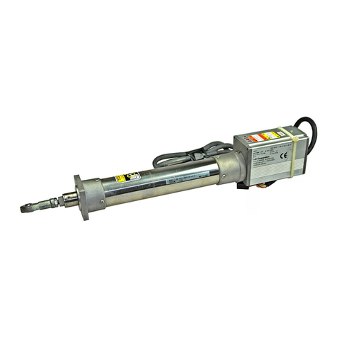
IAI
IAI ROBO Cylinder RCP2 Series User manual

IAI
IAI MCON-C User manual

IAI
IAI ROBO Cylinder RCS4-WRA12C User manual

IAI
IAI XSEL-RA User manual

IAI
IAI ERC Series User manual

IAI
IAI PSEL series User manual

IAI
IAI RCP6 Series User manual

IAI
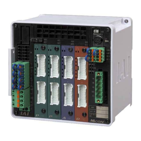
IAI Msep User manual

IAI
IAI ASEP User manual