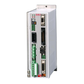
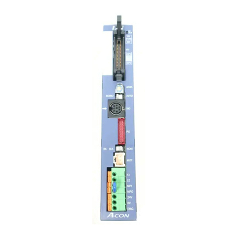
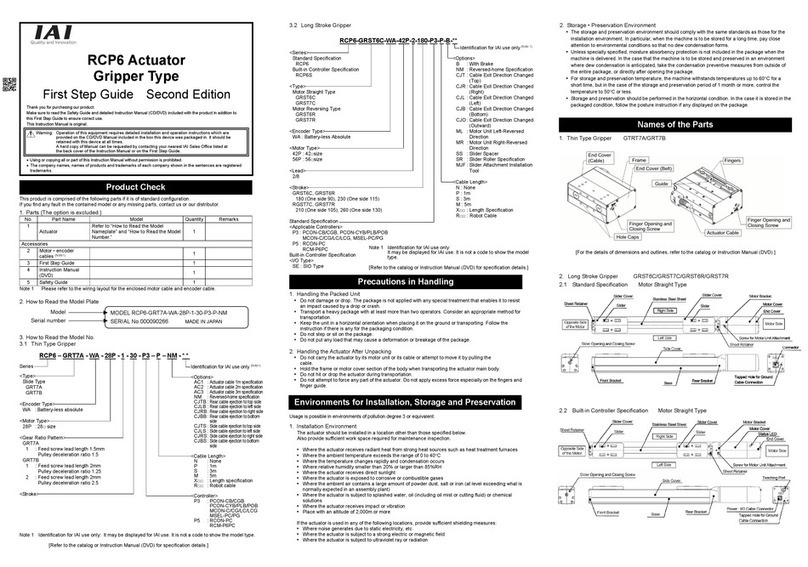
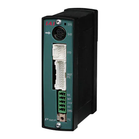
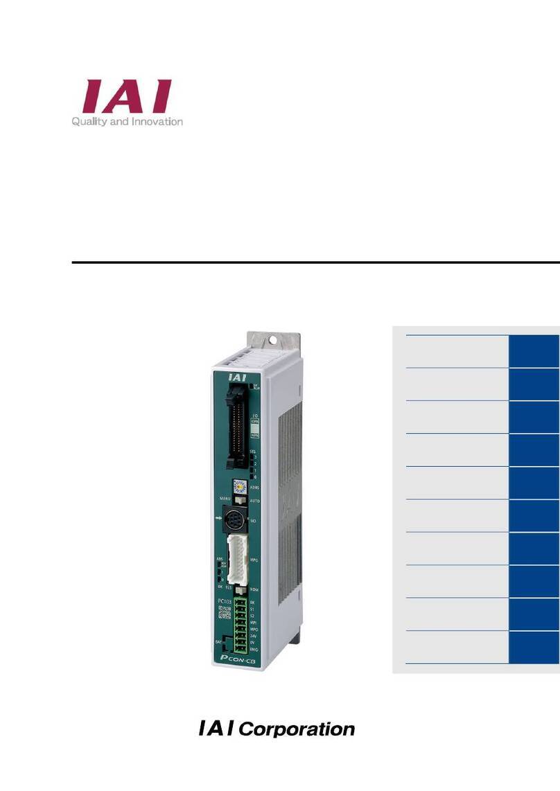
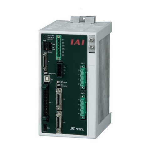
IAI ROBO Cylinder RCP2 Series User manual

Operation Manual Fourth Edition
RCP2 Series
Robo Cylinder Controller

CAUTION
1. Basic Setting of User Parameters
After applying power, at least the three user parameters specified below must be set in accordance
with the specific application.
Inappropriate settings of these parameters will prevent the controller from operating properly, so
exercise due caution.
For details on how to set the user parameters, refer to “User Parameter Settings” in the operation
manual for the PC or teaching pendant.
(1) Selecting the PIO pattern
This controller provides five PIO (Parallel I/O) patterns to meet the needs of various applications.
To select a desired PIO pattern, set a corresponding value from 0 to 4 in user parameter No. 25 (PIO
pattern selection).
The factory setting for this parameter is “0: [Conventional].”
Parameter No.
25 setting Feature of PIO pattern
0 Conventional
This pattern is compatible with the pin assignments of the RCP controller.
1 Standard
All functions of the RCP controller are available, plus the home-return command
input, servo ON input, reset input, moving output and ready output.
2 64-point positioning
Compared with the standard pattern offering only 16 positioning points, this pattern
provides up to 64 positioning points.
However, the servo ON input, ready output and zone output have been removed.
3 2 zone output signals
Compared with the standard pattern offering only one zone output signal, this pattern
provides two zone output signals.
However, the moving output has been removed.
The boundaries for the second zone output signal are specified in user parameter
Nos. 23 and 24.
4 Teaching
This pattern allows for normal positioning operation, as well as jogging and writing of
current position to a specified position using I/Os.
Switching between the normal positioning mode and teaching mode is effected by the
MODE input signal.
The mode switching completion output has been added to indicate that the modes
have been switched.
However, the zone output has been removed.
(Note) Position data can be rewritten up to around 100,000 times.
(2) Enabling/disabling the servo ON input signal (SON)
The servo ON input signal has been added to allow for servo ON/OFF control on the PLC side.
Depending on the needs, therefore, the user must enable/disable this signal.
Setting
Enable (use) the signal 0
Disable (do not use) the signal 1
If “0” or “2” has been selected as the above PIO pattern, the servo ON signal is not provided.
However, you must still set “1: [Disable]” in Parameter #21 (SON). (If “0” is set, the servo will not turn
ON.)
The factory setting for this parameter is “1: [Disable].”

(3) Enabling/disabling the pause signal (*STP)
The pause signal uses the contact B logic to provide a failsafe function.
Therefore, this signal must remain ON in normal conditions of use.
(The pause signal must also remain ON when issuing movement commands from the teaching
pendant or PC.)
Since there are applications where this signal is not used, a parameter is provided to disable the
pause signal so it doesn’t have to be turned ON.
To select a desired setting, set “0” or “1” in user parameter No. 15 (Pause input disable selection).
Setting
Enable (use) the signal 0
Disable (do not use) the signal 1
If the pause input is not used, set “1: [Disable]” in this parameter and the signal need not be turned
ON.
The factory setting for this parameter is “0: [Enable].”
2. Recommendation for Backing up Latest Data
This controller uses nonvolatile memory to store the position table and parameters. Normally the
memory will retain the stored data even after the power is disconnected. However, the data may be
lost if the nonvolatile memory becomes faulty.
(We strongly recommend that the latest position table and parameter data be backed up so that the
data can be restored quickly in the event of power failure, or when the controller must be replaced for
a given reason.)
The data can be backed up using the following methods:
(1) Save to a CD or FD from the PC software.
(2) Hand write the position table and parameter table on paper.
3. Compatibility of Teaching Pendant
The existing teaching pendants of <RCA-T> and <RCA-E> types can be used with the RCP2
controller, but your RCA-T/RCA-E teaching pendant will require some modification.
If you are using a teaching pendant of either type, please send it to IAI. We will perform the
necessary modification and return it to you as soon as possible.
Teaching pendants that have already been modified have a specific code at the end of their serial
number. Please check the serial number of your teaching pendant to see if it requires modification.
Teaching pendant model Code at the end of serial number
RCA-T …E3 (or later)
RCA-E …G3 (or later)
RCA-P …G3 (or later)

Safety Precautions
Please read the information in “Safety Precautions” carefully before selecting a model and using the
product.
The precautions described below are designed to help you use the product safely and avoid bodily injury
and/or property damage.
Directions are classified as “danger,” “warning,” “caution” and “note,” according to the degree of
risk.
Danger Failure to observe the instruction will result in an imminent danger leading to
death or serious injury.
Warning Failure to observe the instruction may result in death or serious injury.
Caution Failure to observe the instruction may result in injury or property damage.
Note The user should take heed of this information to ensure the proper use of the
product, although failure to do so will not result in injury.
This product has been designed and manufactured as a component for use in general industrial
machinery.
Devices must be selected and handled by a system designer, personnel in charge of the actual operation
using the product or similar individual with sufficient knowledge and experience, who has read both the
catalog and operation manual (particularly the “Safety Precautions” section). Mishandling of the product
poses a risk.
Please read the operation manuals for all devices, including the main unit and controller.
It is the user’s responsibility to verify and determine the compatibility of this product with the user’s
system, and to use them properly.
After reading the catalog, operation manual and other materials, be sure to keep them in a convenient
place easily accessible to the personnel using this product.
When transferring or loaning this product to a third party, be sure to attach the catalog, operation manual
and other materials in a conspicuous location on the product, so that the new owner or user can
understand its safe and proper use.
The danger, warning and caution directions in this “Safety Precautions” do not cover every possible case.
Please read the catalog and operation manual for the given device, particularly for descriptions unique to
it, to ensure its safe and proper handling.
Danger
[General]
zDo not use this product for the following applications:
1. Medical equipment used to maintain, control or otherwise affect human life or physical health
2. Mechanisms and machinery designed for the purpose of moving or transporting people
3. Important safety parts of machinery
This product has not been planned or designed for applications requiring high levels of safety. Use of
this product in such applications may jeopardize the safety of human life. The warranty covers only the
product as it is delivered.

[Installation]
zDo not use this product in a place exposed to ignitable, inflammable or explosive substances. The
product may ignite, burn or explode.
zAvoid using the product in a place where the main unit or controller may come in contact with water or
oil droplets.
zNever cut and/or reconnect the cables supplied with the product for the purpose of extending or
shortening the cable length. Doing so may result in fire.
[Operation]
zIf you are using a pace maker or other mechanical implant, do not come within one meter of the
product. Doing so may cause the pace maker, etc., to malfunction.
zDo not pour water onto the product. Spraying water over the product, washing it with water or using it in
water may cause the product to malfunction, resulting in injury, electric shock, fire, etc.
[Maintenance, Inspection, Repair]
zNever modify the product. Unauthorized modification may cause the product to malfunction, resulting in
injury, electric shock, fire, etc.
zDo not disassemble and reassemble the product. Doing so may result in injury, electric shock, fire, etc.
Warning
[General]
zDo not use the product outside the specifications. Using the product outside the specifications may
cause it to fail, stop functioning or sustain damage. It may also significantly reduce the service life of the
product. In particular, observe the maximum loading capacity and speed.
[Installation]
zIf the machine will stop in the case of system problem such as emergency stop or power failure, design
a safety circuit or other device that will prevent equipment damage or injury.
zBe sure to provide Class D grounding for the controller and actuator (formerly Class 3 grounding:
Grounding resistance at 100 Ωor less). Leakage current may cause electric shock or malfunction.
zBefore supplying power to and operating the product, always check the operation area of the equipment
to ensure safety. Supplying power to the product carelessly may cause electric shock or injury due to
contact with the moving parts.
zWire the product correctly by referring to the operation manual. Securely connect the cables and
connectors so that they will not be disconnected or come loose. Failure to do so may cause the product
to malfunction or cause fire.
[Operation]
zDo not touch the terminal block or various switches while the power is supplied to the product. Failure to
observe this instruction may result in electric shock or malfunction.
zBefore operating the moving parts of the product by hand (for the purpose of manual positioning, etc.),
confirm that the servo is turned off (using the teaching pendant). Failure to observe this instruction may
result in injury.
zThe cables supplied with the product are flexible, but they are not robot cables. Do not store the cables
in a movable cable duct (cable bearer, etc.) that bends more than the specified bending radius.
zDo not scratch the cables. Scratching, forcibly bending, pulling, winding, crushing with heavy object or
pinching a cable may cause it to leak current or lose continuity, resulting in fire, electric shock,
malfunction, etc.

zTurn off the power to the product in the event of power failure. Failure to do so may cause the product
to suddenly start moving when the power is restored, thus resulting in injury or product damage.
zIf the product is generating heat, smoke or a strange smell, turn off the power immediately. Continuing
to use the product may result in product damage or fire.
zIf any of the internal protective devices (alarms) of the product has actuated, turn off the power
immediately. Continuing to use the product may result in product damage or injury due to malfunction.
Once the power supply is cut off, investigate and remove the cause and then turn on the power again.
zIf the LEDs on the product do not illuminate after turning on the power, turn off the power immediately.
The protective device (fuse, etc.) on the live side may remain active. Request repair to the IAI sales
office from which you purchased the product.
[Maintenance, Inspection, Repair]
zBefore conducting maintenance/inspection, parts replacement or other operations on the product,
completely shut down the power supply. At this time, take the following measures:
1. Display a sign that reads, “WORK IN PROGRESS. DO NOT TURN ON POWER” at a conspicuous
place, in order to prevent a person other than the operator from accidentally turning on the power.
2. When two or more operators are to perform maintenance/inspection together, always call out every
time the power is turned on/off or an axis is moved in order to ensure safety.
[Disposal]
zDo not throw the product into fire. The product may burst or generate toxic gases.
Caution
[Installation]
zDo not use the product under direct sunlight (UV ray), in a place exposed to dust, salt or iron powder, in
a humid place, or in an atmosphere of organic solvent, phosphate-ester machine oil, etc. The product
may lose its function over a short period of time, or exhibit a sudden drop in performance or its service
life may be significantly reduced.
zDo not use the product in an atmosphere of corrosive gases (sulfuric acid or hydrochloric acid), etc.
Rust may form and reduce the structural strength.
zWhen using the product in any of the places specified below, provide a sufficient shield. Failure to do so
may result in malfunction:
1. Place where large current or high magnetic field is present
2. Place where welding or other operations are performed that cause arc discharge
3. Place subject to electrostatic noise
4. Place with potential exposure to radiation
zInstall the main unit and controller in a place subject to as little dust as possible. Installing them in a
dusty place may result in malfunction.
zDo not install the product in a place subject to large vibration or impact (4.9 m/s2or more). Doing so
may result in the malfunctioning of the product.
zProvide an emergency-stop device in a readily accessible position so the device can be actuated
immediately upon occurrence of a dangerous situation during operation. Lack of such device in an
appropriate position may result in injury.
zProvide sufficient maintenance space when installing the product. Routine inspection and maintenance
cannot be performed without sufficient space, which will eventually cause the equipment to stop or the
product to sustain damage.
zDo not hold the moving parts of the product or its cables during installation. It may result in injury.
zAlways use IAI’s genuine cables for connection between the controller and the actuator. Also use IAI’s
genuine products for the key component units such as the actuator, controller and teaching pendant.

zBefore installing or adjusting the product or performing other operations on the product, display a sign
that reads, “WORK IN PROGRESS. DO NOT TURN ON POWER.” If the power is turned on
inadvertently, injury may result due to electric shock or sudden activation of an actuator.
[Operation]
zTurn on the power to individual equipment one by one, starting from the equipment at the highest level
in the system hierarchy. Failure to do so may cause the product to start suddenly, resulting in injury or
product damage.
zDo not insert a finger or object in the openings in the product. It may cause fire, electric shock or injury.
[Maintenance, Inspection, Repair]
zDo not touch the terminals when performing an insulation resistance test. Electric shock may result. (Do
not perform any withstand voltage test, since the product uses DC voltage.)
Note
[General]
zIf you are planning to use the product under a condition or environment not specified in the catalogs
and operation manual, or in an application requiring strict safety such as aircraft facility, combustion
system, entertainment machine, clean-room environment, safety device or other equipment having
significant impact on human life or property, design operating ranges with sufficient margins from the
ratings and design specifications or provide sufficient safety measures such as fail-safes. Whatever you
do, always consult IAI’s sales representative.
[Installation]
zDo not place objects around the controller that will block airflows. Insufficient ventilation may damage
the controller.
zDo not configure a control circuit that will cause the load to drop in case of power failure. Configure a
control circuit that will prevent the table or load from dropping when the power to the machine is cut off
or an emergency stop is actuated.
[Installation, Operation, Maintenance]
zWhen handling the product, wear protective gloves, protective goggles, safety shoes or other necessary
gear to ensure safety.
[Disposal]
zWhen the product becomes no longer usable or necessary, dispose of it properly as an industrial waste.
Others
QIAI shall not be liable whatsoever for any loss or damage arising from a failure to observe the items
specified in “Safety Precautions.”
QIf you have any question regarding the product, please contact your nearest IAI sales office. The
addresses and phone numbers of our sales offices are provided at the end of this operation manual.

Before Use
QCaution
1. Be sure to read this operation manual to ensure the proper use of this product.
2. Unauthorized use or reproduction of a part or all of this operation manual is prohibited.
3. IAI shall not be liable whatsoever for any loss or damage arising from a handling or operation not
specified in this operation manual.
4. The information contained in this operation manual is subject to change without notice.
QAction to Be Taken in Case of Emergency
* If this product is found to be in a dangerous condition, immediately turn off all power switches of the main unit
and connected equipment or immediately disconnect all power cables from the outlets. (“Dangerous condition”
refers to a situation where the product is generating abnormal heat or smoke or has ignited and a fire or danger
to human health is anticipated.)

Table of Contents
1. Note to the User .................................................................................. 1
1.1 Introduction .................................................................................................................................. 1
1.2 Handling of Secondary Batteries for the Absolute Specification.................................................. 1
1.3 Safety Precautions ....................................................................................................................... 2
1.4 Warranty Period and Scope of Warranty ..................................................................................... 3
2. Specifications ...................................................................................... 4
2.1 Basic Specifications ..................................................................................................................... 4
2.1.1 Backup Batteries for the Absolute Specification .................................................................... 5
2.2 Name and Function of Each Part of the Controller ...................................................................... 6
2.2.1 Names.................................................................................................................................... 6
2.2.2 Functions................................................................................................................................ 6
2.3 External Dimensions .................................................................................................................... 8
2.3.1 Standard Specification .......................................................................................................... 8
2.3.2 Absolute Specification with Battery Bracket........................................................................... 9
Absolute Specification without Battery Bracket .............................................................................. 10
3. Installation and Noise Elimination ..................................................... 11
3.1 Installation Environment..............................................................................................................11
3.2 Power Supply ..............................................................................................................................11
3.3 Noise Elimination and Grounding ...............................................................................................11
3.4 Heat Radiation and Installation .................................................................................................. 13
4. Wiring ................................................................................................ 14
4.1 Internal Drive-Power Cutoff Relay Type..................................................................................... 14
4.1.1 Configuration........................................................................................................................ 14
4.1.2 External Connection Diagram.............................................................................................. 15
4.1.3 Wiring the Power Supply/Emergency-Stop Switch .............................................................. 16
4.2 External Drive-Power Cutoff Relay Type.................................................................................... 23
4.2.1 Configuration........................................................................................................................ 23
4.2.2 External Connection Diagram.............................................................................................. 24
4.2.3 Wiring the Power Supply/Motor Power Cutoff Relay ........................................................... 25
4.3 Connecting the I/O Cables ......................................................................................................... 27
zPIO pattern 0 [Conventional] ...................................................................................................... 27
zPIO pattern 1 [Standard]............................................................................................................. 28
zPIO pattern 2 [64-point positioning]............................................................................................29
zPIO pattern 3 [2 zone output signals] ......................................................................................... 30
zPIO pattern 4 [Teaching]............................................................................................................. 31
4.4 Connecting the Actuator............................................................................................................. 32
4.5 Connecting the Communication Cable ...................................................................................... 35

5. I/O Signal Control and Signal Functions ........................................... 36
5.1 PIO Patterns and Signal Assignments ....................................................................................... 36
5.1.1 Explanation of Signal Names............................................................................................... 37
5.1.2 Signal Assignment Table for Respective PIO Patterns........................................................ 38
5.2 Interface Circuit .......................................................................................................................... 39
5.2.1 External Input Specifications................................................................................................ 39
5.2.2 External Output Specifications............................................................................................. 40
5.3 Details of I/O Signal Functions................................................................................................... 41
5.3.1. Details of Each Input Signal................................................................................................. 41
Start (CSTR) ............................................................................................................................... 41
Servo ON (SON)......................................................................................................................... 41
Alarm reset (RES) ...................................................................................................................... 41
Home return (HOME) ................................................................................................................. 42
Operation mode (MODE) ...........................................................................................................42
Current-position write (PWRT) ...................................................................................................42
Jog (JOG+, JOG-) ...................................................................................................................... 43
Pause (*STP).............................................................................................................................. 43
Command position number (PC1 to PC32)................................................................................ 43
5.3.2 Details of Each Output Signal .............................................................................................. 44
Ready (SRDY)............................................................................................................................ 44
Moving (MOVE) .......................................................................................................................... 44
Position complete (PEND).......................................................................................................... 44
Home return completion (HEND) ............................................................................................... 44
Completed position number (PM1 to PM32) .............................................................................. 45
Zone (ZONE1, ZONE2).............................................................................................................. 45
Current operation mode (MODES)............................................................................................. 45
Write completion (WEND) .......................................................................................................... 45
Alarm (*ALM) .............................................................................................................................. 46
Emergency stop (*EMGS) ..........................................................................................................46
Output Signal Changes in Each Mode ........................................................................................... 47
6. Data Entry <Basics>.......................................................................... 47
6.1 Description of Position-Data Table ............................................................................................. 48
6.1.1 Relationship of Push Force at Standstill and Current-Limiting Value .................................. 50
6.2 Explanation of Modes................................................................................................................. 53
6.2.1 Positioning Mode ................................................................................................................. 53
6.2.2 Push & Hold Mode ............................................................................................................... 53
6.2.3 Speed Change during Movement ........................................................................................ 55
6.2.4 Operation at Different Acceleration and Deceleration Settings ........................................... 55
6.2.5 Pause ................................................................................................................................... 56
6.2.6 Zone Signal Output ..............................................................................................................57
6.2.7 Home Return........................................................................................................................ 57
6.2.8 Teaching Mode (Jogging/Teaching Using PIO) ................................................................... 58

7. Operation <Practical Steps>.............................................................. 59
7.1 How to Start................................................................................................................................ 59
7.1.1 Standard Specification ......................................................................................................... 59
7.1.2 Absolute Specification..........................................................................................................61
7.2 How to Execute Home Return ................................................................................................... 62
7.2.1 Standard Specification ......................................................................................................... 62
7.2.2 Absolute Specification..........................................................................................................63
7.2.3 Operation Timings at PIO Pattern = “0: [Conventional]” ...................................................... 64
7.2.4 Operation Timings at PIO Pattern ≠“0: [Conventional]” ...................................................... 65
7.3 Home Return and Movement after Start (Home Return Not Using the Dedicated Input)
(PIO Pattern = “0: [Conventional]”) ............................................................................................66
7.4 Positioning Mode (Back and Forth Movement between Two Points) ........................................ 68
7.5 Push & Hold Mode ..................................................................................................................... 70
7.6 Speed Change during Movement .............................................................................................. 72
7.7 Operation at Different Acceleration and Deceleration Settings.................................................. 74
7.8 Pause ......................................................................................................................................... 76
7.9 Zone Signal Output .................................................................................................................... 78
7.10 Incremental Moves..................................................................................................................... 80
7.11 Notes on Incremental Mode .......................................................................................................82
7.12 Jogging/Teaching Using PIO......................................................................................................84
8. Parameters........................................................................................ 86
8.1 Parameter Classification ............................................................................................................ 86
8.2 Parameter Table ......................................................................................................................... 86
8.3 Parameter Settings .................................................................................................................... 87
8.3.1 Parameters Relating to the Actuator Stroke Range............................................................. 87
zSoft limit...................................................................................................................................... 87
zZone boundary ........................................................................................................................... 87
zHome return direction ................................................................................................................. 88
zHome return offset...................................................................................................................... 88
8.3.2 Parameters Relating to the Actuator Operating Characteristics .......................................... 88
zPIO jog speed............................................................................................................................. 88
zDefault speed ............................................................................................................................. 88
zDefault acceleration/deceleration ...............................................................................................88
zDefault positioning band (in-position) ......................................................................................... 89
zDefault acceleration only MAX flag ............................................................................................ 89
zPush & hold stop judgment period ............................................................................................. 89
zCurrent-limiting value at standstill during positioning ................................................................. 90
zCurrent-limiting value during home return .................................................................................. 90
8.3.3 Parameters Relating to the External Interface..................................................................... 90
zPIO pattern selection .................................................................................................................. 90
zPause input disable selection..................................................................................................... 91
zServo ON input disable selection ............................................................................................... 91
zSerial communication speed ......................................................................................................91
zMinimum delay time for slave transmitter activation .................................................................. 91

8.3.4 Servo Gain Adjustment ........................................................................................................ 91
zServo gain number ..................................................................................................................... 91
9. Controlling Multiple Controllers via Serial Communication................ 92
9.1 Basic Specifications ................................................................................................................... 92
9.2 Connection Example .................................................................................................................. 92
9.3 SIO Converter ............................................................................................................................ 93
9.4 Address Switch .......................................................................................................................... 95
9.5 Connection Cables..................................................................................................................... 95
9.6 Detail Connection Diagram ........................................................................................................ 96
10. Troubleshooting................................................................................. 97
10.1 Action to Be Taken upon Occurrence of Problem ...................................................................... 97
10.2 Alarm Level Classification.......................................................................................................... 98
10.3 Alarm Description Output Using PIO ......................................................................................... 99
10.4 Alarm Description and Cause/Action ....................................................................................... 100
(1) Message level alarms ........................................................................................................ 100
(2) Operation-cancellation level alarms................................................................................... 101
(3) Cold-start level alarms ....................................................................................................... 104
10.5 Messages Displayed during Operation Using the Teaching Pendant or PC Software ............ 106
10.6 Specific Problems..................................................................................................................... 108
zI/O signals cannot be exchanged with the PLC. ...................................................................... 108
zThe RDY lamp does not illuminate after the power is input. .................................................... 108
zOnly the RDY lamp illuminates when the servo ON signal is input after the power
was input. ................................................................................................................................. 108
zBoth the RDY lamp and ALM lamp illuminate when the power is input. .................................. 108
zHome return ends in the middle in a vertical application.......................................................... 109
zNoise occurs during downward movements in a vertical application....................................... 109
zVibration occurs when the actuator is stopped. ....................................................................... 109
zThe actuator overshoots when decelerated to a stop. ............................................................. 109
zThe home and target positions sometimes shift....................................................................... 109
zThe speed is slow during push & hold operation. .................................................................... 109
zThe actuator moves only a half of, or twice as much as, the specified movement...................110
* Appendix .................................................................................................111
Example of Basic RCP2 Positioning Sequence .....................................................................................111
Recording of Position-Data Table ...........................................................................................................114
Recording of User Parameters ...............................................................................................................116

1
1. Note to the User
1.1 Introduction
Thank you for purchasing the RCP2 controller. This manual explains the features and operating
procedures of the product.
If not used or handled properly, even a brilliant product cannot fully demonstrate its function or may cause
an unexpected breakdown or end its life prematurely. Please read this manual carefully and handle the
product with utmost care while ensuring its correct operation. Keep this manual in a convenient place so
the relevant sections can be referenced readily when necessary.
If you are also using any of IAI’s various actuators and/or optional PC software or teaching pendant, also
refer to the operation manual for each item.
1.2 Handling of Secondary Batteries for the Absolute Specification
Observe the safety precautions specified below when handling the secondary batteries:
1. Never attempt to disassemble the batteries. Strong alkali battery fluid will damage the skin or clothes.
2. Never short the battery terminals (i.e. by allowing the positive and negative terminals to make direct
contact). Doing so may damage the equipment or cause burns due to the generation of heat.
3. Never throw the batteries into a fire, because it may cause them to explode. Also avoid immersing the
batteries in water, which can result in loss of battery function.
4. Do not solder the batteries directly. The safety valve inside the battery cap may be damaged, resulting
in a breakdown of the safety mechanism.
5. If the battery connector remains connected for a long time without a supply of power, a deep discharge
may occur and cause the battery fluid to leak or allow the battery performance or life to
deteriorate/shorten significantly. If the equipment is to be relocated or modified and the power will not
be supplied for a prolonged period, first disconnect the battery connector.
6. When disposing of used batteries, drop them into the collection box at an authorized recycle store or
take other appropriate steps.
* We have made every effort to ensure accuracy of the information provided in this manual. Should you
find an error, however, or if you have any comment, please contact IAI.
Keep this manual in a convenient place so it can be referenced readily when necessary.

2
1.3 Safety Precautions
Read the following information carefully and provide safety measures with due consideration.
This system product has been developed as a drive component for automated machinery and the like, and
is therefore designed not to generate excessive torque or speed beyond the levels needed to drive
automated equipment. However, the following instructions must be strictly observed to prevent an
unexpected accident.
1. Do not handle this product in any manner not specified in this manual. If you have questions regarding
any of the information provided in this manual, please contact IAI.
2. Always use the specified genuine parts to wire your RCP2 controller and an actuator.
3. Do not enter the operating range of the machine while the machine is operating or is able to operate
(the controller power is ON). If the machine is used in a place accessible to other people, enclose its
operating range using a safety cage, etc.
4. Always turn off the power supply to the controller before assembling/adjusting or
maintaining/inspecting the machine. During assembly/adjustment or maintenance/inspection, put a
plate or other visible sign in a conspicuous place indicating that work is in progress. The operator
should keep the entire power cable beside him or her to prevent another person from inadvertently
plugging in the cable.
5. If two or more persons work together, set signaling methods so each person can confirm the safety of
other(s) during work. Especially when the work requires an axis or axes to be moved—with or without
the power and by motor drive or manual operation—the person moving each axis should always call
out beforehand to ensure safety.
6. If you have extended a cable or made other alteration to the standard wiring specification, thoroughly
check the wiring and ensure absence of problem before turning on the power, in order to prevent
malfunction due to miswiring.

3
1.4 Warranty Period and Scope of Warranty
The RCP2 controller you have purchased passed IAI’s shipping inspection implemented under the
strictest standards. The unit is covered by the following warranty:
1. Warranty Period
The warranty period shall be one of the following periods, whichever ends first:
•18 months after shipment from our factory
•12 months after delivery to a specified location
2. Scope of Warranty
If an obvious manufacturing defect is found during the above period under an appropriate condition of
use, IAI will repair the defect free of charge. Note, however, that the following items are excluded from
the scope of warranty:
•Aging such as natural discoloration of coating
•Wear of a consumable part due to use
•Noise or other sensory deviation that doesn’t affect the mechanical function
•Defect caused by inappropriate handling or use by the user
•Defect caused by inappropriate or erroneous maintenance/inspection
•Defect caused by use of a part other than IAI’s genuine part
•Defect caused by an alteration or other change not approved by IAI or its agent
•Defect caused by an act of God, accident, fire, etc.
The warranty covers only the product as it has been delivered and shall not cover any losses arising in
connection with the delivered product. The defective product must be brought to our factory for repair.
Please read carefully the above conditions of warranty.

4
2. Specifications
2.1 Basic Specifications
Specification item Internal Drive-Power Cutoff Relay
Type
External Drive-Power Cutoff Relay
Type
Model RCP2-C RCP2-CG
Number of controlled axes 1 axis/unit
Supply voltage 24 VDC ±10%
Supply current 2 A max.
Control method Weak field-magnet vector control (patent pending)
Positioning command Position number specification
Direct specification
Position number Standard 16 points, maximum 64 points
Backup memory Position number data and parameters are saved in nonvolatile memory.
Serial EEPROM can be rewritten 100,000 times.
PIO 10 dedicated inputs/10 dedicated outputs. Selectable from five patterns.
LED indicators RDY (green), RUN (green), ALM (red)
Communication RS485 1 channel (terminated externally)
Encoder interface Incremental specification conforming to EIA RS-422A/423A
Forced release of
electromagnetic brake Toggle switch on front panel of enclosure
Actuator cable: 20 m or less
Cable length
PIO cable: 5 m or less
Insulation strength 500 VDC, 10 MΩ
Environment Operating
temperature 0 to 40°C
Operating
humidity 85%RH or less (non-condensing)
Operating
environment Not subject to corrosive gases.
Storage
temperature -10 to 65°C
Storage
humidity 90%RH or less (non-condensing)
Vibration
resistance
10 to 57 Hz in XYZ directions / Pulsating amplitude: 0.035 mm
(continuous), 0.075 mm (intermittent)
Protection class 1P20
Weight 300 g or less
External dimensions 35 W x 178.5 H x 68.1 D mm

5
2.1.1 Backup Batteries for the Absolute Specification
The absolute-specification controller uses secondary batteries (nickel metal hydride cells) to retain
absolute counter data in the FPGA (field-programmable gate array) after the power is cut off, and also to
supply power to the encoder’s drive circuit intermittently.
(1) Battery specification
Item Description
Classification Cylindrical sealed nickel metal hydride cell
Manufacturer Matsushita Battery Industrial
Model AB-4
Nominal voltage 4.8 V (1.2 V x 4)
Rated capacity 1900 mAh (average capacity: 2050 mAh)
Average life Approx. 4 years
Charging time Approx. 48 hours (at ambient temperature of 20°C)
Retention time after power cutoff Approx. 250 hours (when the batteries are fully charged, at
ambient temperature of 20°C)
(2) Charging the batteries
Be sure to charge the batteries when the controller is powered up for the first time after delivery, and also
after new batteries have been installed.
The batteries are charged automatically while the power is being supplied to the controller, so keep the
main power on for at least 48 hours.
The actuator can be moved and the position table changed while the batteries are charging.
Additionally, charge the batteries for at least 48 hours after the power supply to the controller has been cut
off for a prolonged period (within the specified battery-retention time).
(3) Replacing the batteries
Batteries are consumable parts. Repeated charging and discharging of the batteries will diminish their
initial performance characteristics. If the retention time has decreased significantly, the batteries may have
reached the end of their useful life. If this should occur, replace the batteries.
The batteries should be replaced approximately four years after the controller is first connected to your
equipment, although the specific timing will vary depending on the ambient temperature and conditions of
charge/discharge.
The label on the battery unit shows a reference date, which is four years from the shipment date. Use this
date to determine when the batteries should be replaced.
Note: (1) Applying vibration, impact or other external force to the actuator or moving the slider, etc.,
while the power is off will erase the absolute data.
When the power is input again, the *ALM signal will turn OFF, the ALM lamp will illuminate
and the message “Absolute encoder error (2)” or “Absolute encoder error (3)” will be
displayed.
In this case, you must reset the alarm and perform a home return.
Never move the slider or rod while the power is off!
(2) It is recommended that the batteries be charged at normal temperature (+10 to +30°C) to
prevent extreme temperatures from negatively affecting the charging efficiency.
Temperatures exceeding 45°C may cause performance deterioration or the leakage of
battery fluid.

6
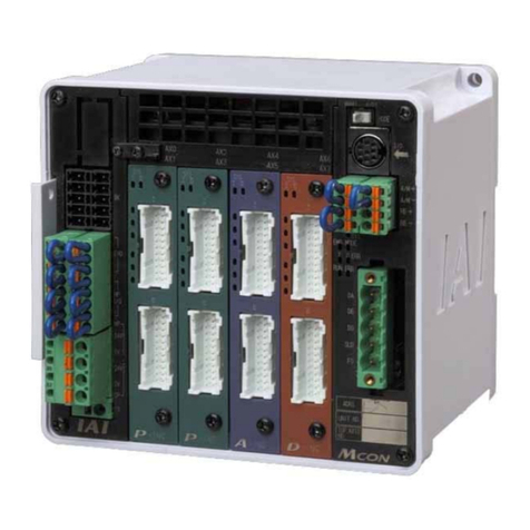
2.2 Name and Function of Each Part of the Controller
2.2.1 Names
2.2.2 Functions
(1) Battery connector
A connector for the absolute data retention batteries.
(2) Status indicator LEDs
RDY: When lit, this LED indicates that 24V power is supplied and the CPU is operating.
RUN: This LED indicates the servo status. Lit = Servo is ON, Unlit = Servo is OFF.
ALM: When lit, this LED indicates that an alarm is present, or an emergency stop has been actuated
or the motor drive power is cut off.
(3) PIO pattern number label (IOPN)
Write down the PIO pattern selected in user parameter No. 25 on this label.
(This will facilitate maintenance if multiple controllers are used in different patterns.)
(4) Teaching pendant/PC connector (SIO)
A connector for the dedicated teaching pendant or PC communication cable.
This cable is also used to link two or more controllers to enable serial communication among them.
RDY (green) •RUN (green) •ALM (red)
(2) Status indicator LEDs
(3) PIO pattern number label
(4) Teaching pendant/
PC connector
(5) Motor connector
(6) Power/emergency-stop
terminal block
(7) I/O signal connector
(8) Address switch
(9) PORT switch
(10) Encoder connector
(11) Brake release switch
(1) Battery connector
(absolute specification)

7
(5) Motor connector (MOT)
A connector for the actuator’s motor power cable.
(6) Power/emergency-stop terminal block
[Built-in cutoff relay type RCP2-C]
S1, S2
Provide a contact output for the emergency-stop button on the teaching pendant.
Port switch ON = Emergency-stop button output (Contact B)
Port switch OFF = ON in normal conditions of use (Emergency-stop button output is
disabled)
MPI, MPO
Provide a contact for cutting off the motor drive power. MPI and MPO represent the
input side and output side of the motor power supply, respectively. (Short these
terminals using a jumper wire if not used. The controller is shipped with MPI and
MPO shorted.)
24V Positive side of the 24-V power supply
N Negative side of the 24-V power supply
EMG Emergency-stop input
[External cutoff relay type RCP2-CG]
S1, S2
Provide a contact output for the emergency-stop button on the teaching pendant.
Port switch ON = Emergency-stop button output (Contact B)
Port switch OFF = ON in normal conditions of use (Emergency-stop button output is
disabled)
MPI, MPO
Provide a contact for cutting off the motor drive power. MPI and MPO represent the
input side and output side of the motor power supply, respectively. (Connect an
external safety circuit.)
24V Positive side of the 24-V power supply
N Negative side of the 24-V power supply
FG FG of the 24-V power supply
(7) I/O signal connector (PIO)
A PIO cable connector to the host controller (PLC, etc.).
(8) Address switch (ADRS)
A switch for setting the address for the controller axis.
If two or more controllers are connected in the serial communication mode, do not specify duplicate
controller addresses.
Setting range: 0 to F (A maximum of 16 controllers can be connected.)
(9) PORT switch (PORT)
A switch for enabling/disabling the serial communication port.
Set this switch to ON when connecting the controller to a teaching pendant or PC. Set it to OFF if no
teaching pendant or PC is connected.
* If this switch is turned ON without connecting a teaching pendant or PC, an emergency stop will be
actuated.
(10) Encoder connector (ENC)
A connector for the actuator’s encoder/brake cables.
(11) Brake release switch (BK)
A switch for forcibly releasing the brake when the actuator is used with a brake option.
RLS: Brake is forcibly released
NOM: Normal setting (Brake is controlled by the controller)

8
2.3 External Dimensions
2.3.1 Standard Specification (RCP2-***-I )
An external view and dimensions of the product are shown below.
170.5 (Mounting dimension)
163
178.5
φ
5
68.1
5
35
Other manuals for ROBO Cylinder RCP2 Series
8
This manual suits for next models
1
Table of contents
Other IAI Controllers manuals
Popular Controllers manuals by other brands

Daktronics
Daktronics SPORTSOUND SSR-200 GEN II Operation manual

Woodward
Woodward DTSC-200 installation manual

Jamara
Jamara COOL RUNNING 081458 Instruction

PEITIAN ROBOTICS
PEITIAN ROBOTICS ARC5 Series manual

DERUN LIGHTING TECHNOLOGY
DERUN LIGHTING TECHNOLOGY DR-CON-IR20M-3CH-LV user manual

National Instruments
National Instruments PXI-7356 Getting started