manuals.online logo
Brands
  1. Home
  2. •
  3. Brands
  4. •
  5. iArmor
  6. •
  7. Automobile Accessories
  8. •
  9. iArmor EDGE IA-N179 User manual

iArmor EDGE IA-N179 User manual

Rev. 20220501
1
iArmor®
Customer Support: [email protected]
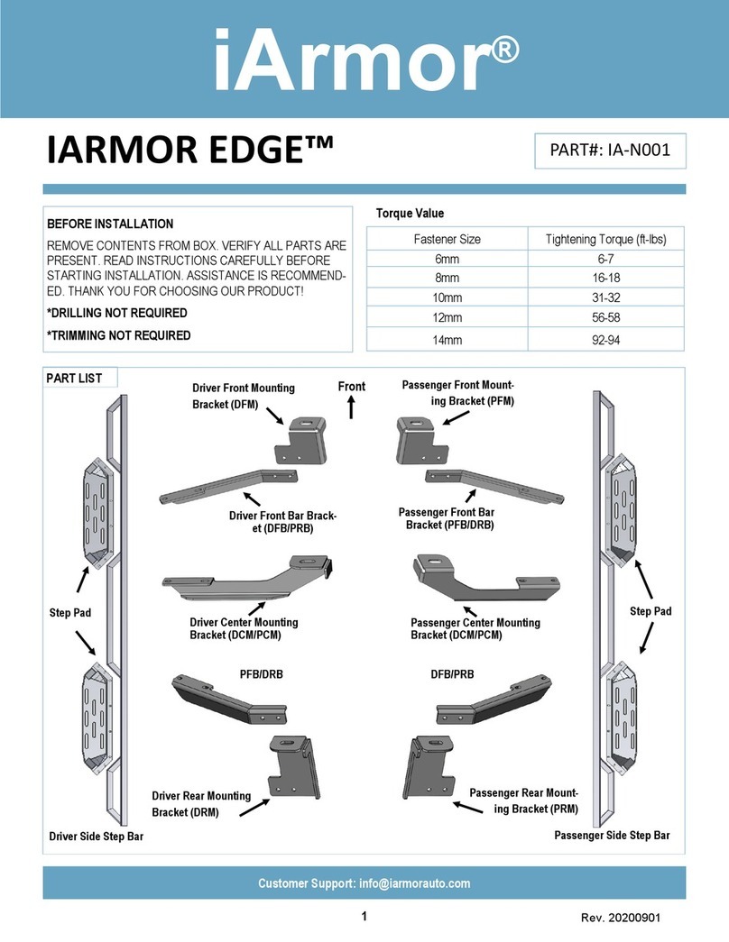
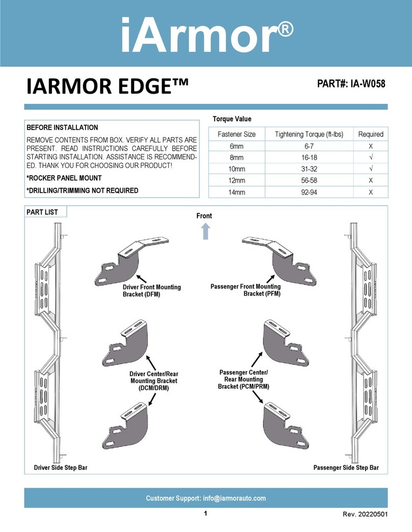
IARMOR EDGE™PART#: IA-N179&N208&N209
BEFORE INSTALLATION
REMOVE CONTENTS FROM BOX. VERIFY ALL PARTS
ARE PRESENT. READ INSTRUCTIONS CAREFULLY
BEFORE STARTING INSTALLATION. ASSISTANCE IS
RECOMMENDED. THANK YOU FOR CHOOSING OUR
PRODUCT!
*ROCKER PANEL MOUNT
*DRILLING MAYBE REQUIRED
Fastener Size Tightening Torque (ft-lbs) Required
6mm 6-7 √
8mm 16-18 √
10mm 31-32 X
12mm 56-58 X
14mm 92-94 X
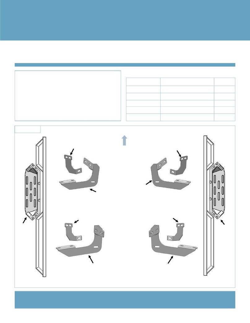
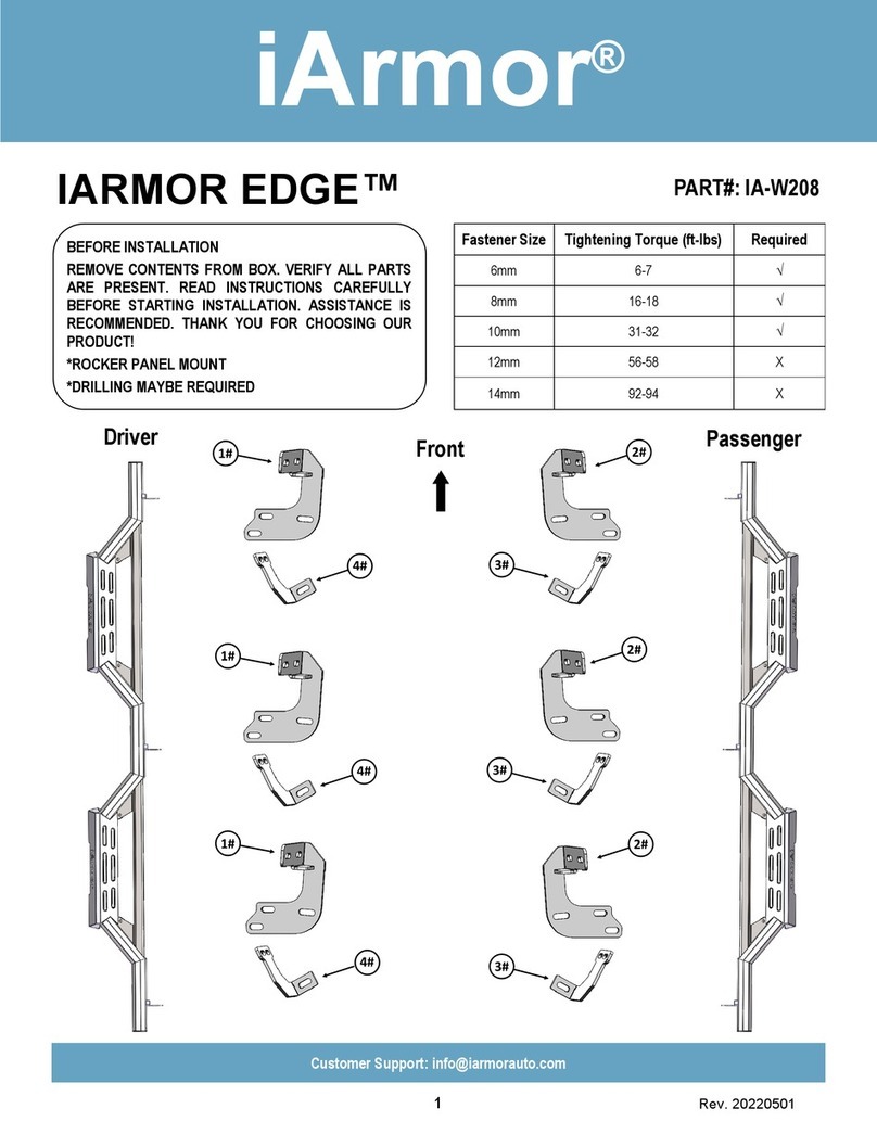
Front PassengerDriver
2#
1#
4# 3#
4# 3#
2#
1#
4#
1#
3#
2#
Rev. 20220501
2
iArmor®
Customer Support: [email protected]
11 # 13 #
12 # 14 #
5 # 8 #7 #6 #
10 #
9 #
Hardware Package
Item QTY Description Item QTY Description
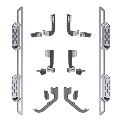
1# 3Driver Side Mounting Brackets 9# 12 M8 Lock Washers
2# 3Passenger Side Mounting Brackets 10# 6M8X1.25 Nylon Lock Nuts
3# 3Passenger Side Support Brackets 11# 6M8X1.25 Hex Nuts
4# 3Driver Side Support Brackets 12# 12 M6X1-25 Hex Bolt
5# 6M8 Bolt/Nut Plates 13# 68 M6 Large Flat Washers
6# 6M8 Plastic Washers 14# 56 M6X1 Nylon Lock Nuts
7# 18 M8X1.25-30 Hex Bolts 15# 44 M6X1-20 T-Bolts
8# 24 M8 Large Flat Washers
15 #
Rev. 20220501
3
iArmor®
Customer Support: [email protected]
STEP 1
Install the Step Pads onto the step bars with (32) M6X1-20mm
T-Bolts, (32) M6 Large Flat Washers and (32) M6X1 Nylon
Lock Nuts.
IMPORTANT: Don’t hit the step pad with any metal hummer
within step pad installation, or the step pad will be damaged.
The instruction here is for your reference only. We strongly
recommend the professional installer for best result. We are not
responsible for any damage caused by the installation.
STEP 2
Starting installation from the driver side front of the vehicle,
remove the sealing tape covering the factory holes on the inner
side of body panel if equipped, (Fig 1).
Note: All Mounting Brackets and Supporting Brackets for
Driver Side are the same.
(8) M6X1-20mm T-Bolts
(8) M6 Large Flat Washers
(8) M6X1 Nylon Lock Nuts
Note: Rotate 90° after inserting the T-Bolts
into the Channel!!!
STEP 3
Determine the correct procedure to attach (1) Driver Front
Mounting Bracket for your model/year:
Models without factory threaded inserts in body panel:
a. Partially thread (1) M8X1.25-30mm Hex Bolt into the
threaded end of (1) M8 Bolt/Nut Plate, (Fig 2). Thread the
hex bolt in until it is flush with the welded nut, (Fig 3). Use
the M8 hex bolt as a handle and insert the Bolt/Nut Plate
into the oval hole, (Fig 4). Feed the threaded bolt of the
Bolt/Nut plate through one of the hex shaped factory
holes. Thread (1) M8 Plastic Washer onto the threaded
end and down tight against the body panel, (Fig 5). Then
remove the M8 Hex Bolt.
NOTE: The Plastic washer is designed to keep the Bolt/Nut
Plate from falling into the body panel and to aid in bracket
installation.
Front
(Fig 1) Driver Side Front Mounting Location
(No factory holes on pinch weld on some trims)
(Fig 2) M8 Bolt/Nut Plate (NOTE: M8 Bolt/Nut Plate is not required
on models with threaded inserts on body panel)
Welded Nut
Welded Bolt
Rev. 20220501
4
iArmor®
Customer Support: [email protected]
(Fig 3) Thread (1) M8X1.25-30mm Hex Bolt into the nut on the
plate. Stop when bolt reaches end of nut as pictured)
(Fig 4) Use the loose Hex Bolt as a handle. Insert the Bolt/Nut
Plate into the oval hole and feed the threaded end out either fac-
tory hex shaped hole.
(Fig 5) Thread Plastic Washer onto the bolt to hold the Bolt/Nut
Plate in position
Note:Do Not Remove The Hex Bolt Until The M8 Plastic Washer
Has Been Threaded Onto the Welded Bolt.
M8 Plastic Washer
Flush
(1) M8X1.25-30mm Hex Bolt
b. Select (1) Driver Front Mounting Bracket. Attach the mount-
ing bracket to the welded bolt end of the M8 Bolt/Nut Plate with
(1) M8 Large Flat Washer, (1) M8 Lock Washer and (1)
M8X1.25 Hex Nut, (Fig 6A). Do not fully tighten at this time.
Hold the welded bolt on the M8 Bolt/Nut Plate and rotate the
Bolt/Nut Plate until the welded nut lines up with the remaining
hex hole on the body panel.
(Fig 6A) Attach Driver Front Mounting Bracket To the Welded
Bolt on M8 Bolt/Nut Plate
(1) M8 Large Flat Washer
(1) M8 Lock Washer
(1) M8X1.25 Hex Nut
Rotate M8 Bolt/Nut Plate To Line
Up the Welded Nut With the Hex
Hole on Body Panel (See Arrow)
c. Secure the Driver Front Mounting Bracket to the welded nut
on the M8 Bolt/Nut Plate with (1) M8X1.25-30mm Hex Bolt, (1)
M8 Lock Washer and (1) M8 Large Flat Washer, (Fig 6B). Do
not fully tighten hardware at this time.
(Fig 6B) Secure Driver Front Mounting Bracket To the Weld-
ed Nut on M8 Bolt/Nut Plate
Welded Nut on
M8 Bolt/Nut Plate
(1) M8X1.25-30mm Hex Bolt
(1) M8 Lock Washer
(1) M8 Large Flat Washer
Rev. 20220501
5
iArmor®
Customer Support: [email protected]
(Fig 7) Driver Side Front Mounting Location
(example of models with factory threaded inserts)
STEP 4
Attach the Driver Front Support Bracket to the Driver Front
Mounting Bracket with (1)M8X1.25-30 Hex Bolt, (2) M8 Large
Flat Washers and (1) M8X1.25 Nylon Lock Nut, (Fig 9).
Rotate and attach the support bracket to the back of the pinch
weld. Line up the slots in the top of the Support Bracket with
the (2) factory holes on the pinch weld (Fig 7). Secure the
Bracket to the back of the pinch weld with (2) M6X1-25 Hex
Bolts, (4) M6 Flat Washers and (2) M6X1 Nylon Lock Nuts, (Fig
10). Do not fully tighten hardware at this time.
IMPORTANT: Some models are not equipped with factory
holes and will require drilling through the pinch weld to
attach the Support Bracket. Do not drill through pinch weld
at this time, (Refer to Step 7).
Models with factory threaded inserts:
Attach Driver Front Mounting Bracket to the threaded inserts
with (2) M8X1.25-30mm Hex Bolts, (2) M8 Lock Washers and
(2) M8 Large Flat Washers, (Figs 7 & 8). Do not fully tighten
hardware at this time.
Front
(2) M8X1.25-30mm Hex Bolts
(2) M8 Lock Washers
(2) M8 Large Flat Washers
(Fig 8) Driver Front Mounting Bracket Installation
(For Models With Factory Threaded Inserts. Bolt Plate
Is Not Required Here)
Driver Front
Support
Bracket
Driver Front
Mounting Bracket
(1) M8X1.25-30mm Hex Bolt
(2) M8 Large Flat Washers
(1) M8X1.25 Nylon Lock Nut
(Fig 9) Attach Driver Front Support Bracket to the Driver Front
Mounting Bracket
Factory holes on pinch weld
Factory threaded
holes on body
panel
Rev. 20220501
6
iArmor®
Customer Support: [email protected]
STEP 6
Once all (3) Brackets have been installed, attach the Assem-
bled Driver Side Step Bar to the Mounting Brackets with (6)
M6X1-20 T-Bolts, (6) M6 Flat Washers and (6) M6X1 Nylon
Lock Nuts (Fig 13). Do not fully tighten hardware at this time.
STEP 7
Properly level and adjust the Step Bar and fully tighten all hard-
ware.
Models requiring drilling for driver side Support Brackets:
a. Make sure the Step Bar is level to the vehicle. Adjust and
tighten all mounting hardware.
b. Line up the slots on the Support Brackets with the back of
the pinch weld. Mark the location of the slots onto the pinch
weld.
c. Drill (2) 1/4” holes through the pinch weld for each Support
Bracket. IMPORTANT: Do not drill too close to the bottom edge
of the pinch weld. Adjust the Brackets as necessary to move
the slots up the body panel away from the edge. Drill the holes
toward the outside of the marked slots.
d. Attach each Support Brackets to the pinch weld with (2)
M6X1-25 Hex Bolts, (4) M6 Large Flat Washers and (2) M6X1
Nylon Lock Nuts, (Fig 10). Check for level then fully tighten all
hardware.
(Fig 10) Attach Driver Front Support Bracket to back of pinch
weld (Models with factory holes on pinch weld only, Some Mod-
els May Require to Drill Holes on Pinch Weld)
(2) M6X1-25 Hex Bolts
(4) M6 Large Flat Washers
(2) M6X1 Nylon Lock Nuts
STEP 5
Move along the side of the body panel to the center and rear
mounting locations, (Figs 11-12). Repeat Steps 2-4 to install
the driver side center & rear Brackets, (Fig 14).
(Fig 11) Driver Side Center Mounting location
(Fig 12) Driver Side Rear Mounting Location
Rear
Front
Rev. 20220501
7
iArmor®
Customer Support: [email protected]
STEP 8
Move to the passenger side of the vehicle. Repeat Steps 2-7 to
install the passenger side step bar.
NOTE: All Mounting Brackets and Support Brackets for
passenger side are the same.
Attention
Do periodic inspections to the installation to make sure
that all hardware is secure and tight.
In order to protect your bars/boards, please use mild
soap/non-abrasive products for cleaning only.
(Fig 13) Driver Side Step Bar Installed
Warning: Install the T-bolt on the step
bar and rotate it to 90 degrees!!!
(6) M6X1-20 T-Bolts
(6) M6 Large Flat Washers
(6) M6X1 Nylon Lock Nuts
Front

This manual suits for next models

2

Other iArmor Automobile Accessories manuals

iArmor EDGE User manual

iArmor

iArmor EDGE User manual

iArmor EDGE IA-W084 User manual

iArmor

iArmor EDGE IA-W084 User manual

iArmor IA-N001 User manual

iArmor

iArmor IA-N001 User manual

iArmor IARMOR EDGE IA-N179&N208 User manual

iArmor

iArmor IARMOR EDGE IA-N179&N208 User manual

iArmor IA-N179 User manual

iArmor

iArmor IA-N179 User manual

iArmor EDGE IA-W171 User manual

iArmor

iArmor EDGE IA-W171 User manual

iArmor EDGE IA-N002 User manual

iArmor

iArmor EDGE IA-N002 User manual

iArmor EDGE IA-W058 User manual

iArmor

iArmor EDGE IA-W058 User manual

iArmor EDGE User manual

iArmor

iArmor EDGE User manual

iArmor EDGE IA-W208 User manual

iArmor

iArmor EDGE IA-W208 User manual

iArmor EDGE IA-N295 User manual

iArmor

iArmor EDGE IA-N295 User manual

iArmor EDGE IA-N095 User manual

iArmor

iArmor EDGE IA-N095 User manual

iArmor EDGE User manual

iArmor

iArmor EDGE User manual

iArmor EDGE IA-N098 User manual

iArmor

iArmor EDGE IA-N098 User manual

iArmor EDGE IA-N044H User manual

iArmor

iArmor EDGE IA-N044H User manual

iArmor EDGE User manual

iArmor

iArmor EDGE User manual

iArmor EDGE IA-N007 User manual

iArmor

iArmor EDGE IA-N007 User manual

iArmor EDGE IA-N175 User manual

iArmor

iArmor EDGE IA-N175 User manual

iArmor EDGE IA-N060H User manual

iArmor

iArmor EDGE IA-N060H User manual

iArmor EDGE IA-N095 User manual

iArmor

iArmor EDGE IA-N095 User manual

iArmor IARMOR EDGE IA-N208 User manual

iArmor

iArmor IARMOR EDGE IA-N208 User manual

Popular Automobile Accessories manuals by other brands

bilsteingroup febi 103650 manual

bilsteingroup

bilsteingroup febi 103650 manual

Gator ETX installation guide

Gator

Gator ETX installation guide

aFe Power 46-39102 instruction manual

aFe Power

aFe Power 46-39102 instruction manual

IBASE Technology MPT-7000VSM user manual

IBASE Technology

IBASE Technology MPT-7000VSM user manual

Roadmaster 1149-107 installation instructions

Roadmaster

Roadmaster 1149-107 installation instructions

Opel VIVARO Infotainment manual

Opel

Opel VIVARO Infotainment manual

Havis-Shields Brow Mount KR-1531-24-SP-KOV datasheet

Havis-Shields

Havis-Shields Brow Mount KR-1531-24-SP-KOV datasheet

Yakima 8007078 quick start guide

Yakima

Yakima 8007078 quick start guide

Joie gemm instruction manual

Joie

Joie gemm instruction manual

Paser UNICO DUAL PLUS installation manual

Paser

Paser UNICO DUAL PLUS installation manual

Whispbar K377 Fitting instructions

Whispbar

Whispbar K377 Fitting instructions

RBO RBO3015 product manual

RBO

RBO RBO3015 product manual

Painless Performance 10309 instructions

Painless Performance

Painless Performance 10309 instructions

Metra Electronics Chrysler 300 installation instructions

Metra Electronics

Metra Electronics Chrysler 300 installation instructions

Conceptronic CNB90CAR quick guide

Conceptronic

Conceptronic CNB90CAR quick guide

dirna Bergstrom Bycool Scania Compact 1.4 PGR Mounting instructions

dirna Bergstrom

dirna Bergstrom Bycool Scania Compact 1.4 PGR Mounting instructions

Yakima Q10 installation instructions

Yakima

Yakima Q10 installation instructions

Kleinn RS-GM6 installation guide

Kleinn

Kleinn RS-GM6 installation guide

manuals.online logo
manuals.online logoBrands
  • About & Mission
  • Contact us
  • Privacy Policy
  • Terms and Conditions

Copyright 2025 Manuals.Online. All Rights Reserved.