iArmor®
Rev. 20200401
5
STEP4
Rear
Front
(Fig 7B) Attach Driver Side Mounting Bracket to threaded end of
the M8 Bolt/Nut Plate
Front
Models with factory threaded inserts:
Attach Driver Side Front Mounting Bracket to the threaded in-
serts with (2) M8x1.25-30mm Hex Bolts, (2) M8 Lock Washers
and (2) M8 Flat Washers, (Fig 8 & 9). Leave hardware loose.
(1)M8X1.25-30mm Hex Bolt
(1)M8 Lock Washer
(1)M8mm Flat Washer
(Fig 8) Driver Side Front Mounting Location mid 2015-on, an
example of models with factory installed threaded inserts
Front
(2) M8X1.25-30mm Hex Bolts
(2) M8 Lock Washers
(2) M8 Flat Washers
(Fig 9) Driver Side Front Mounting Bracket for models w/ facto-
ry installed threaded inserts(M8 Bolt/Nut Plate not required)
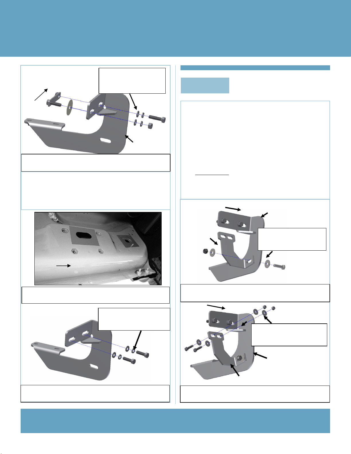
Attach the Driver Side Front Support Bracket (DFS/DCS/DRS)
to the Driver Side Front Mounting Bracket (DFM/DCM/DRM)
with (1)M8x1.25-30mm Hex Bolt, (2)M8 Flat Washers and (1)
M8X1.25 Nylon Lock Nut, (Fig 10). Rotate the support bracket
to the back of the pinch weld. Line up the slots in the top of the
Support Bracket with the (2) factory holes in the pinch weld.
Attach the Bracket to the back of the pinch weld with (2) M6x1-
25mm Hex Bolts, (4) M6 Flat Washers and (2) M6X1 Nylon
Lock Nuts, (Fig 11 & 12). Do not fully tighten hardware at this
time. IMPORTANT: Some models are not equipped with
factory holes and will require drilling through the pinch
weld to attach the Support Bracket. Do not drill through
pinch weld at this time, (see Step 8).
(Fig 10) Attach Driver Side Front Support Bracket to Drive Side
Front Mounting Bracket
Front
(1) M8X1.25-35mm Hex Bolt
(2) M8 Flat Washers
(1) M8X1.25 Nylon Lock Nut
DFM/DCM/DRM
DFS/DCS/DRS
(Fig 11) Attach Driver Side Front Support Bracket to back of
pinch weld (models with factory holes in pinch weld only)
Front
(2) M6X1-25mm Hex Bolts
(4) M6 Large Flat Washers
(2) M6X1 Nylon Lock Nuts
DFM/DCM/DRM
DFS/DCS/DRS
DFM/DCM/DRM