manuals.online logo
Brands
  1. Home
  2. •
  3. Brands
  4. •
  5. IBM
  6. •
  7. Printer
  8. •
  9. IBM 5400-006 Manual

IBM 5400-006 Manual

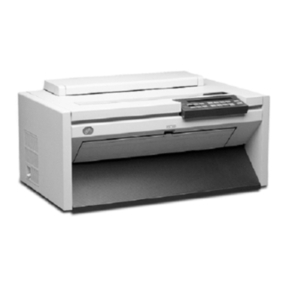
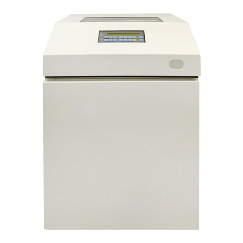
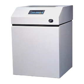
IBM 5400-006 Printer
Setup Instruction and Operator's Guide
Document Number GA18-7709-0
February 4, 1999
IFC Co., Ltd.
Development
T. Greenwood
YMTVM2
VIFC040
LAX-Y74
0462-73-3372
First Edition, March 1999
Changes are made occasionally to the information herin; any such changes will be reported in subsequent revisions or Technical
Newsletters.
 Copyright International Business Machines Corporation 1999. All rights reserved.
Safety Instructions
This instruction manual describes safety instructions for safe, correct use of the product. Please keep it in
a handy place for reference as required.
Icons
In this instruction manual and on safety instruction labels on the product, icons are used for correct use
without causing danger to yourself and other people and for preventing damage to other properties. The
icons used and their meanings are as follows:
Indication by Danger/Caution Labels
If there is a label showing an instruction in black characters on a yellow base either outside or inside of
the product, it is a danger or caution label. Always observe the indicated instruction.
If there are any instructions indicated by a danger or caution label (on the product for example) aside from
the instructions in this manual, always observe the instructions indicated on the label.
DANGER:
This icon indicates a danger of death or serious injury if the product is
handled incorrectly by ignoring the corresponding instruction.
CAUTION:
This icon indicates a danger of personal injury or physical damage if
the product is handled incorrectly by ignoring the corresponding
instruction.
 Copyright IBM Corp. 1999 iii
DANGER:
Do not open a cover not described in the operator's guide. It is dangerous because a live portion
applied with a high voltage exists in side the cover.
Do not modify this product as it might cause a fire or shock hazard.
Do not apply any voltage other than the indicated supply voltage as it might cause a fire or shock
hazard.
Neither use any cord other than the power cord supplied with the product nor use the supplied cord for
other than this product as it might cause a fire or shock hazard.
Do not scratch, damage or process the power cord. If a heavy thing is placed on it or if it is stretched
or bent forcibly, the power cord might be damaged to cause a fire or shock hazard.
DANGER:
Cable Installation and Removal Procedures
Electrical current from the power cord is hazardous. To avoid shock hazard, connect and disconnect
cables as follows when installing or moving this product.
– To connect:
1. Turn everything to Off.
2. Connect the interface cable.
3. Attach the power cord to outlet.
4. Set the device to On.
– To disconnect:
1. Turn everything to Off.
2. Remove the power cord from outlet.
3. Remove the all cables from device.
CAUTION:
When disconnecting the power plug, do not pull the power cord. The cord might be damaged and
cause a fire or shock hazard. (Always hold the plug portion and pull it for disconnection.)
Refer to “Environmental Conditions” described in this manual for the operating environment.
Do not install the product in a humid or dusty place as it might cause a fire or shock hazard.
Do not stop up the ventilation hole of the product. Otherwise, the inside of the product might be
heated abnormally to cause a fire.
iv IBM 5400-006 Printer: Setup Instruction and Operator's Guide
Preface
This manual describes the installation and operation procedures of the IBM 5400 Printer. This manual is
intended for operators and personnel in charge of installation.
Composition of Manual
This manual contains following:
Chapter 1, “Installation” provides the procedure required for installation of the IBM 5400-006 printer and
the test method for checking if the IBM 5400 works normally.
Chapter 2, “Operation” describes names and functions of controls and lamps of the IBM 5400 and basic
operating instructions.
Chapter 3, “Problem Determination Procedure” describes how to handle problems occurring in the IBM
5400-006 printer.
Chapter 4, “IBM 5400-006 Features” describes the features of the IBM 5400-006 printer divided between
system and parallel port.
Chapter 5, “Installation Planning and Site Preparation” describes what is necesary for planning the instal-
lation of the IBM 5400-006 printer.
Appendixes contain the following:
Appendix A, Forms Design
Appendix B, IBM 5400 System Configuration
Appendix C, Control Codes
Appendix D, ESC/P-C Mode and ESC/PC Control Modes
Appendix E, DC 12V Outlet
 Copyright IBM Corp. 1999 v
vi IBM 5400-006 Printer: Setup Instruction and Operator's Guide
Contents
Safety Instructions . . . . . . . . . . . . . . . . . . . . . . . . . . . . . . . . . . . . . . . . . . . . . . . . iii
Icons . . . . . . . . . . . . . . . . . . . . . . . . . . . . . . . . . . . . . . . . . . . . . . . . . . . . . . . . . iii
Indication by Danger/Caution Labels ....................................... iii
Preface . . . . . . . . . . . . . . . . . . . . . . . . . . . . . . . . . . . . . . . . . . . . . . . . . . . . . . . v
Composition of Manual .............................................. v
Chapter 1. Installation . . . . . . . . . . . . . . . . . . . . . . . . . . . . . . . . . . . . . . . . . . . . . 1-1
1.1 Before Installation . . . . . . . . . . . . . . . . . . . . . . . . . . . . . . . . . . . . . . . . . . . . . . 1-1
1.2 Setting up the IBM 5400-006 Printer ................................... 1-3
1.2.1 Peeling off all Shipping Tape and Confirming Accessories ................... 1-3
1.2.2 Setting the Power Cord ....................................... 1-7
1.2.3 Setting the V cable .......................................... 1-8
1.2.4 Setting the Form Guide ........................................ 1-9
1.2.5 Setting the Ribbon Cassette .................................... 1-10
1.2.6 Setting the Test Form ........................................ 1-15
1.2.7 Testing the IBM 5400-006 Printer ................................. 1-20
1.3 Connecting to the Host System ..................................... 1-22
1.3.1 Connecting to an AS/400 System ................................. 1-22
1.3.2 Connecting to a PC (Using a Parallel Port) ........................... 1-26
Chapter 2. Operation . . . . . . . . . . . . . . . . . . . . . . . . . . . . . . . . . . . . . . . . . . . . . 2-1
2.1 Names and Functions ........................................... 2-1
2.1.1 Front View . . . . . . . . . . . . . . . . . . . . . . . . . . . . . . . . . . . . . . . . . . . . . . . 2-1
2.1.2 Rear View . . . . . . . . . . . . . . . . . . . . . . . . . . . . . . . . . . . . . . . . . . . . . . . 2-2
2.1.3 Printer Mechanism (Left View) .................................... 2-3
2.1.4 Printer Mechanism (Right View) ................................... 2-4
2.1.5 Operator Panel . . . . . . . . . . . . . . . . . . . . . . . . . . . . . . . . . . . . . . . . . . . . . 2-5
2.2 Check before Operating ......................................... 2-8
2.2.1 Consumables . . . . . . . . . . . . . . . . . . . . . . . . . . . . . . . . . . . . . . . . . . . . . . 2-8
2.3 Powering On and Off ............................................ 2-9
2.3.1 Powering On . . . . . . . . . . . . . . . . . . . . . . . . . . . . . . . . . . . . . . . . . . . . . . 2-9
2.3.2 Powering Off . . . . . . . . . . . . . . . . . . . . . . . . . . . . . . . . . . . . . . . . . . . . . 2-11
2.4 Starting and Stopping Printing ...................................... 2-12
2.4.1 Stopping and Restarting Printing ................................. 2-12
2.5 Changing the Print Mode ........................................ 2-13
2.5.1 Changing the Print Mode ...................................... 2-14
2.5.2 Changing the Initialization ..................................... 2-15
2.5.3 Print Modes . . . . . . . . . . . . . . . . . . . . . . . . . . . . . . . . . . . . . . . . . . . . . . 2-15
2.6 Unloading and Setting the Printing Form ............................... 2-18
2.6.1 Unloading the Printing Form .................................... 2-18
2.6.2 Setting the Printing Form ...................................... 2-22
2.6.3 At EOF . . . . . . . . . . . . . . . . . . . . . . . . . . . . . . . . . . . . . . . . . . . . . . . . 2-30
2.7 Checking the Ribbon ........................................... 2-31
2.8 Replacing the Ribbon ........................................... 2-33
2.8.1 Removing the Ribbon Cassette .................................. 2-33
2.8.2 Setting and Mounting the Ribbon Cassette ........................... 2-35
2.8.3 Refilling the Ribbon ......................................... 2-40
2.9 Making Adjustments . . . . . . . . . . . . . . . . . . . . . . . . . . . . . . . . . . . . . . . . . . . 2-47
2.9.1 Adjusting the Print Pressure .................................... 2-47
 Copyright IBM Corp. 1999 vii
2.9.2 Adjusting the Vertical Position ................................... 2-49
2.9.3 Adjusting the Horizontal Position ................................. 2-50
2.9.4 Adjusting Form Tension ....................................... 2-53
2.10 Test Printing . . . . . . . . . . . . . . . . . . . . . . . . . . . . . . . . . . . . . . . . . . . . . . . 2-54
2.11 Changing the Door Direction ...................................... 2-56
2.11.1 Changing the Front Door ..................................... 2-56
2.11.2 Changing the Rear Door ..................................... 2-61
2.12 Initializing the Printer .......................................... 2-65
2.12.1 Switches used for Initialization and Their Functions ...................... 2-65
2.12.2 Initialization Procedure Example ................................. 2-66
2.12.3 Initial Set Items ........................................... 2-68
2.13 Host Trace Printing ........................................... 2-77
2.14 Relocating the IBM 5400-006 Printer ................................. 2-78
Chapter 3. Problem Determination Procedure .............................. 3-1
3.1 Problem Determination . . . . . . . . . . . . . . . . . . . . . . . . . . . . . . . . . . . . . . . . . . . 3-1
3.2 Messages and Actions .......................................... 3-2
3.2.1 Message List . . . . . . . . . . . . . . . . . . . . . . . . . . . . . . . . . . . . . . . . . . . . . . 3-2
3.3 Form Jam Recovery ............................................ 3-5
3.4 Ribbon Jam Recovery ........................................... 3-8
3.5 Inspecting the Platen and Changing Strike Position ......................... 3-11
3.5.1 Inspecting the Platen ........................................ 3-11
3.5.2 Changing Strike Position ...................................... 3-13
Chapter 4. IBM 5400-006 Features ..................................... 4-1
4.1 IBM 5400-006 Features .......................................... 4-1
4.1.1 Basic Functions . . . . . . . . . . . . . . . . . . . . . . . . . . . . . . . . . . . . . . . . . . . . 4-3
4.2 Connecting to a Host System ....................................... 4-6
4.2.1 System Port . . . . . . . . . . . . . . . . . . . . . . . . . . . . . . . . . . . . . . . . . . . . . . 4-6
4.2.2 Connecting to a Parallel Port ..................................... 4-7
4.3 System Port Basic Functions ....................................... 4-8
4.3.1 Printable Characters . . . . . . . . . . . . . . . . . . . . . . . . . . . . . . . . . . . . . . . . . . 4-8
4.3.2 Printing Density . . . . . . . . . . . . . . . . . . . . . . . . . . . . . . . . . . . . . . . . . . . 4-11
4.3.3 Printing Speed . . . . . . . . . . . . . . . . . . . . . . . . . . . . . . . . . . . . . . . . . . . . 4-11
4.3.4 Printing Style (Vertical, Horizontal) ................................ 4-12
4.4 Parallel Port Basic Functions ...................................... 4-13
4.4.1 Support Emulation and Character Set .............................. 4-13
4.4.2 Line Spacing (No. of lines per inch: lpi) ............................. 4-14
4.4.3 Printing Speed . . . . . . . . . . . . . . . . . . . . . . . . . . . . . . . . . . . . . . . . . . . . 4-14
Chapter 5. Installation Planning and Site Preparation ......................... 5-1
5.1.1 Site Preparation . . . . . . . . . . . . . . . . . . . . . . . . . . . . . . . . . . . . . . . . . . . . 5-1
5.1.2 Physical Specifications . . . . . . . . . . . . . . . . . . . . . . . . . . . . . . . . . . . . . . . . 5-2
5.1.3 Power Requirements . . . . . . . . . . . . . . . . . . . . . . . . . . . . . . . . . . . . . . . . . 5-3
5.1.4 Cables . . . . . . . . . . . . . . . . . . . . . . . . . . . . . . . . . . . . . . . . . . . . . . . . . . 5-3
5.1.5 Environmental Conditions . . . . . . . . . . . . . . . . . . . . . . . . . . . . . . . . . . . . . . 5-4
Appendix A. Forms Design . . . . . . . . . . . . . . . . . . . . . . . . . . . . . . . . . . . . . . . . . A-1
A.1 Forms Specifications . . . . . . . . . . . . . . . . . . . . . . . . . . . . . . . . . . . . . . . . . . . . A-1
A.2 Printable Area . . . . . . . . . . . . . . . . . . . . . . . . . . . . . . . . . . . . . . . . . . . . . . . . A-3
A.3 Multiple-Part Forms Glue Fastening Specifications .......................... A-4
A.4 Preprinting . . . . . . . . . . . . . . . . . . . . . . . . . . . . . . . . . . . . . . . . . . . . . . . . . . A-5
A.5 Label Forms . . . . . . . . . . . . . . . . . . . . . . . . . . . . . . . . . . . . . . . . . . . . . . . . . A-6
A.6 Maximum Number of Characters per Line ................................ A-7
viii IBM 5400-006 Printer: Setup Instruction and Operator's Guide
A.6.1 When Connected to the AS/400 ................................... A-7
A.6.2 Connecting to a PC .......................................... A-8
Appendix B. Print Control Characters (Connected to a System Port) ................ B-1
B.1.1 System Printer Control Characters (SCS Mode) ......................... B-1
B.2 Bar Code Print Function .......................................... B-3
Appendix C. Control Codes (Connected to a Parallel Port) ...................... C-1
C.1 Control Code List .............................................. C-1
C.2 Overview of Control Codes ........................................ C-4
C.2.1 Terms . . . . . . . . . . . . . . . . . . . . . . . . . . . . . . . . . . . . . . . . . . . . . . . . . . C-4
C.2.2 Conditions to Start Printing ..................................... C-4
C.3 Control Codes . . . . . . . . . . . . . . . . . . . . . . . . . . . . . . . . . . . . . . . . . . . . . . . . C-6
C.4 Considerations in Creating a 5577 Data Stream ........................... C-22
C.4.1 About Level E Printers ....................................... C-22
C.4.2 Printer Initial Values ......................................... C-23
C.4.3 Character Layout . . . . . . . . . . . . . . . . . . . . . . . . . . . . . . . . . . . . . . . . . . C-24
C.4.4 Difference Between Line Pitch and Actual Line Pitch Distance ................ C-27
C.4.5 Setting a Format (Setting a Print Area and Tabs and Moving the Print ........... C-28
C.4.6 Specifying a Font Style ....................................... C-29
C.4.7 Combining Character Decorations ................................ C-29
C.4.8 Printing Data Exceeding the Right Margin ............................ C-30
Appendix D. ESC/P-C Mode and ESC/P-C Control Modes ....................... D-1
D.1 Initialization for ESC/P-C ......................................... D-1
D.2 Control Codes . . . . . . . . . . . . . . . . . . . . . . . . . . . . . . . . . . . . . . . . . . . . . . . . D-1
D.2.1 Limits When Using ESC/P-C Mode ................................. D-4
D.3 ESC/P-C Character Set .......................................... D-5
Appendix E. DC 12V Outlet ......................................... E-1
Contents ix
xIBM 5400-006 Printer: Setup Instruction and Operator's Guide

Before Installation
Chapter 1. Installation
1.1 Before Installation
Before installing the IBM 5400-006 printer, check and execute the following items:
Check if the environment of the installation site and power supply meet the
conditions defined in Chapter 5, “Installation Planning and Site Preparation” on
page 5-1.
DANGER:
Note: To avoid careless electric shock, do not connect the power cord to an
outlet unless instructed. To connect and disconnect a communication
cable, remove the power cord from the outlet.
The customer is assumed to prepare the forms for testing the IBM 5400 Printer
(15" wide continuous form). For details of the forms, refer to Appendix A,
“Forms Design.”
An interface cable is required to connect the IBM 5400-006 printer to the host
system. The customer is assumed to prepare the interface cable.
Check if all parts are duly supplied. If any items are missing or damaged, call
your IBM marketing representative. Accessories are included in the IBM
5400-006 printer package.
IBM 5400-006 Printer
 Copyright IBM Corp. 1999 1-1
Before Installation
Moving the IBM 5400-006 Printer
Before moving the IBM 5400-006 printer, unlock the two wheels in the front.
Then, push the printer to the desired location with the help of two or more
persons.
Note: If the printer is moved with the wheels locked, the floor and the wheels
might be damaged.
Set the printer in the desired location. Lock the wheels at the front to stabilize
the printer.
Note: Set the printer on a horizontal and flat floor. Make sure that the wheels
are not tangled with the cable or the cords.
1-2 IBM 5400-006 Printer: Setup Instruction and Operator's Guide
Peeling off all Shipping Tape and Confirming Accessories
1.2 Setting up the IBM 5400-006 Printer
1.2.1 Peeling off all Shipping Tape and Confirming Accessories
1
Open the set cover and peel off all shipping tape. Close the set cover.
Chapter 1. Installation 1-3
Peeling off all Shipping Tape and Confirming Accessories
2
Open the rear door. Peel off the shipping tape fixing the ribbon cassette and
the accessory box.
3
Make sure that the following items are provided.
Ø Ribbon Cassette
Ø Accessory Box
1-4 IBM 5400-006 Printer: Setup Instruction and Operator's Guide

Peeling off all Shipping Tape and Confirming Accessories
4
Make sure the following items are provided in the accessory box,
Ø Setup Instruction and Opera-
tor's Guide (this book)
Ø Maintenance Information
Manual
Ø V Cable
Ø Curl Corrector
Ø Rear Fence
Ø Power Cord
Chapter 1. Installation 1-5
Peeling off all Shipping Tape and Confirming Accessories
5
Open the front door of the printer and insert the two manuals.
1-6 IBM 5400-006 Printer: Setup Instruction and Operator's Guide
Setting the Power Cord
1.2.2 Setting the Power Cord
1
Open the rear door.
2
Take the cover off of the hole in the back left part of the stacker. Push the
cover from below with your hand to take it out. (This cover is not used
again.)
3
Insert the power cord plug into the power connector on the top left of the
stacker and thread the power cord through the hole in the bottom. Then, fix
the cable with the three cable clamps.
Note: Pull the power cord out from the hole in the left of the stacker outside
the printer with the shortest length. If the power cord is loose inside the
stacker, it may cause a stacker jam.
Note:
Use a power plug with three prongs. Do not plug a three-prong power cord into
a two-prong power plug. This might cause poor printing.
Chapter 1. Installation 1-7
Setting the V-cable
1.2.3 Setting the V cable
If you are using the parallel port to connect to a PC, refer to 1.2.4, “Setting the
Form Guide” on page 1-9.
1
Open the rear door.
2
Connect the V-cable to interface panel. Fasten the two screws of the
V-cable.
3
Fix the V-cable to the stacker using the cable clamp below the interface
panel.
1-8 IBM 5400-006 Printer: Setup Instruction and Operator's Guide
Setting the Form Guide
1.2.4 Setting the Form Guide
Set the rear fence and curl corrector for a continuous form 15" wide and 11" long
used for test printing.
1
Open the rear door.
2
Set the rear fence at scale position “11”, referring to the figure.
3
Set the curl corrector at scale position “10” to “12”.
4
Close the rear door.
Chapter 1. Installation 1-9
Setting the Ribbon Cassette
1.2.5 Setting the Ribbon Cassette
First, set the ribbon cassette itself.
1
Take the ribbon cassette out of the box. Open the cassette arms on the left
and right in the arrow direction. Then, make sure that the ribbon passes
through the guides.
2
Open the ribbon cassette cover in the direction indicated. Remove the paper
spacer.
3
Press the button in the direction indicated and close the ribbon roller.
1-10 IBM 5400-006 Printer: Setup Instruction and Operator's Guide

Other manuals for 5400-006

1

Other IBM Printer manuals

IBM Bertl Quick guide

IBM

IBM Bertl Quick guide

IBM 221 User manual

IBM

IBM 221 User manual

IBM 6400 Series Manual

IBM

IBM 6400 Series Manual

IBM 5256 User manual

IBM

IBM 5256 User manual

IBM InfoPrint 6500 User manual

IBM

IBM InfoPrint 6500 User manual

IBM 6400 Series User manual

IBM

IBM 6400 Series User manual

IBM 5400-006 Parts list manual

IBM

IBM 5400-006 Parts list manual

IBM InfoPrint 1585n User manual

IBM

IBM InfoPrint 1585n User manual

IBM 5225 Manual

IBM

IBM 5225 Manual

IBM 4100 User manual

IBM

IBM 4100 User manual

IBM 4400-006 - 4400 Model 006 B/W Direct Thermal User manual

IBM

IBM 4400-006 - 4400 Model 006 B/W Direct Thermal User manual

IBM 4247 Setup guide

IBM

IBM 4247 Setup guide

IBM Network Printer 12 Specification sheet

IBM

IBM Network Printer 12 Specification sheet

IBM RS/6000 44P Series 270 User manual

IBM

IBM RS/6000 44P Series 270 User manual

IBM Infoprint Color 1354 Product information sheet

IBM

IBM Infoprint Color 1354 Product information sheet

IBM 102 User manual

IBM

IBM 102 User manual

IBM 4610 SureMark GR3 Operating instructions

IBM

IBM 4610 SureMark GR3 Operating instructions

IBM Infoprint Color 8 User manual

IBM

IBM Infoprint Color 8 User manual

IBM 60 User manual

IBM

IBM 60 User manual

IBM 5218 Manual

IBM

IBM 5218 Manual

IBM 24 User manual

IBM

IBM 24 User manual

IBM Infoprint 1130 User manual

IBM

IBM Infoprint 1130 User manual

IBM INFOPRINT COLOUR 1767 User manual

IBM

IBM INFOPRINT COLOUR 1767 User manual

IBM 1585 (MT 4539) User manual

IBM

IBM 1585 (MT 4539) User manual

Popular Printer manuals by other brands

PosDelta T90 user guide

PosDelta

PosDelta T90 user guide

VEVOR KH-5030 Operation instructions

VEVOR

VEVOR KH-5030 Operation instructions

Star MP212FP-24-A Specification and operating instructions

Star

Star MP212FP-24-A Specification and operating instructions

Epson 1400 - Stylus Photo Color Inkjet Printer user guide

Epson

Epson 1400 - Stylus Photo Color Inkjet Printer user guide

Sony UP-CX2 Service manual

Sony

Sony UP-CX2 Service manual

Canon TS700 Series Getting started

Canon

Canon TS700 Series Getting started

LG PD269SF owner's manual

LG

LG PD269SF owner's manual

Condre EZ/CD Print 6500 Software guide

Condre

Condre EZ/CD Print 6500 Software guide

Konica Minolta BIZHUB C353P user guide

Konica Minolta

Konica Minolta BIZHUB C353P user guide

Canon TS700 Series Getting started

Canon

Canon TS700 Series Getting started

Epson Stylus Photo R270 Series Start here

Epson

Epson Stylus Photo R270 Series Start here

WOOSIM PORTI-SM40 Operator's manual

WOOSIM

WOOSIM PORTI-SM40 Operator's manual

Brother 7050N - HL B/W Laser Printer Quick setup guide

Brother

Brother 7050N - HL B/W Laser Printer Quick setup guide

BIXOLON SRP-S300 user manual

BIXOLON

BIXOLON SRP-S300 user manual

Canon imagePROGRAF iPF6450 Basic guide

Canon

Canon imagePROGRAF iPF6450 Basic guide

Lexmark E250D - E B/W Laser Printer Service manual

Lexmark

Lexmark E250D - E B/W Laser Printer Service manual

Adler TP700 user manual

Adler

Adler TP700 user manual

SATO HT200e Configuration guide

SATO

SATO HT200e Configuration guide

manuals.online logo
manuals.online logoBrands
  • About & Mission
  • Contact us
  • Privacy Policy
  • Terms and Conditions

Copyright 2025 Manuals.Online. All Rights Reserved.