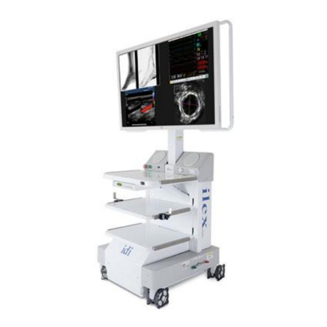
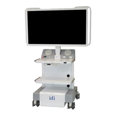
idi MDS Administrator Guide

Made in the USA
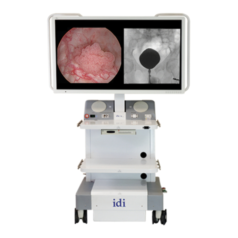
MDS
Mobile Display System
Installation & Operator
Manual

Installation & Operator Manual for MDS
L280-0960 Rev. C www.imagediagnostics.com i
The text of this manual was originally written, approved and published by the manufacturer in English.
OVERVIEW
This manual pertains to the specified devices only and does not intended to replace or substitute for certified
training in the application of this equipment. The device is intended for qualified medical personnel who
have been trained in the use of medical equipment.
Functional capabilities and operation of the equipment described herein can be employed in a variety of
diagnostic, therapeutic, and surgical applications.
OWNER RESPONSIBILITIES
The owner of this device is responsible to ensure system compatibility, the qualifications of the operator and
maintenance personnel. The operator must be properly trained and have obtained credentials from the
appropriate authorities.
This equipment must be installed in an area provided with the proper electrical power.
The owner of this device is responsible for verifying continued compliance with all applicable regulations
and standards. Consult local, state, federal and/or international agencies regarding specific requirements and
regulations applicable to the use of this equipment.
Image Diagnostics, Inc. certifies only the equipment. After-sale operating practices and safety are the
responsibility of the owner and operator. Image Diagnostics, Inc. assumes no liability or responsibility for
after-sale operating or safety practices; nor can it be responsible for personal injury or damage resulting from
misuse.
Never make modifications or adjustments to the equipment unless directed by a qualified Image Diagnostics
representative. This equipment, when properly assembled, meets US federal regulations and international
standards. Unauthorized modifications to the equipment may impact adherence to these standards and make
the equipment unsafe to operate.
CUSTOMER SUPPORT
Image Diagnostics will make available, on request, circuit diagrams, component part lists, calibration
instructions, or other information which will assist the user’s appropriately qualified technical personnel to
repair those parts of equipment which are designated by the manufacturer as repairable.
For technical assistance, call IDI at (978) 829-0009 or send fax to (978) 829-0027. Be prepared to give the
complete model and serial number found on the data label on the base of the MDS at the time of contact.

Installation & Operator Manual for MDS
L280-0960 Rev. C www.imagediagnostics.com ii
Table of Contents
1. SYMBOL IDENTIFICATION............................................................................................. 1
2. INTENDED USE & ESSENTIAL PERFORMANCE....................................................... 2
3. SAFETY INSTRUCTIONS.................................................................................................. 2
4. SAFETY HAZARDS............................................................................................................. 3
5. EMC (Electromagnetic Compatibility) STATEMENT ..................................................... 5
6. INSTALLATION INSTRUCTIONS................................................................................... 6
6.1. Mount Two Main Monitors........................................................................................... 7
6.2. Release Monitor Counterbalance ................................................................................. 9
6.3. Shelf Adjustment.......................................................................................................... 10
6.4. Clean Unit..................................................................................................................... 11
6.5. Electronics Installation................................................................................................ 11
7. OPERATOR INSTRUCTIONS......................................................................................... 12
7.1. Moving the MDS Unit.................................................................................................. 12
7.2. Moving Monitor Positions........................................................................................... 13
8. MAINTENANCE, SERVICE & REPAIR........................................................................ 14
8.1. Recommended Periodic Performance Checks........................................................... 14
8.2. Service & Repair Statement........................................................................................ 15
9. TROUBLESHOOTING...................................................................................................... 15
10. DISPOSAL OF COMPONENTS....................................................................................... 15
11. SPECIFICATIONS/PRODUCT DATA............................................................................ 16
12. WARRANTY....................................................................................................................... 17

Installation & Operator Manual for MDS
L280-0960 Rev. C www.imagediagnostics.com 1
1. SYMBOL IDENTIFICATION
Attention! Consult accompanying documents.
Failure to follow these instructions could cause serious
personal injury or damage to equipment. Consult all
accompanying documents.
Warning! Information or instructions shown near this symbol must be adhered
to in order to prevent a potentially hazardous situation which if not avoided,
could result in death, personal injury or damage to the equipment.
Recyclable material.
Protective Ground. This is the common tie point between the AC Electrical
Power Cord Ground, Frame Ground, and Controller Ground.
SGS North America, Inc. Testing Service.
European Authorized
Representative:
Model of Video Integration System.
Serial Number of Video Integration System.
Indication of European Conformity for sale in the European Economic Area
(EEA).
Date of manufacture of the Video Integration System.
Location where the Video Integration System was manufactured.
Alternating Current (AC).
EC
REP
REF
SN
or
Advena Ltd. Tower Business Centre, 2nd Flr.,
Tower Street, Swatar, BKR 4013 Malta

Installation & Operator Manual for MDS
L280-0960 Rev. C www.imagediagnostics.com 2
2. INTENDED USE & ESSENTIAL PERFORMANCE
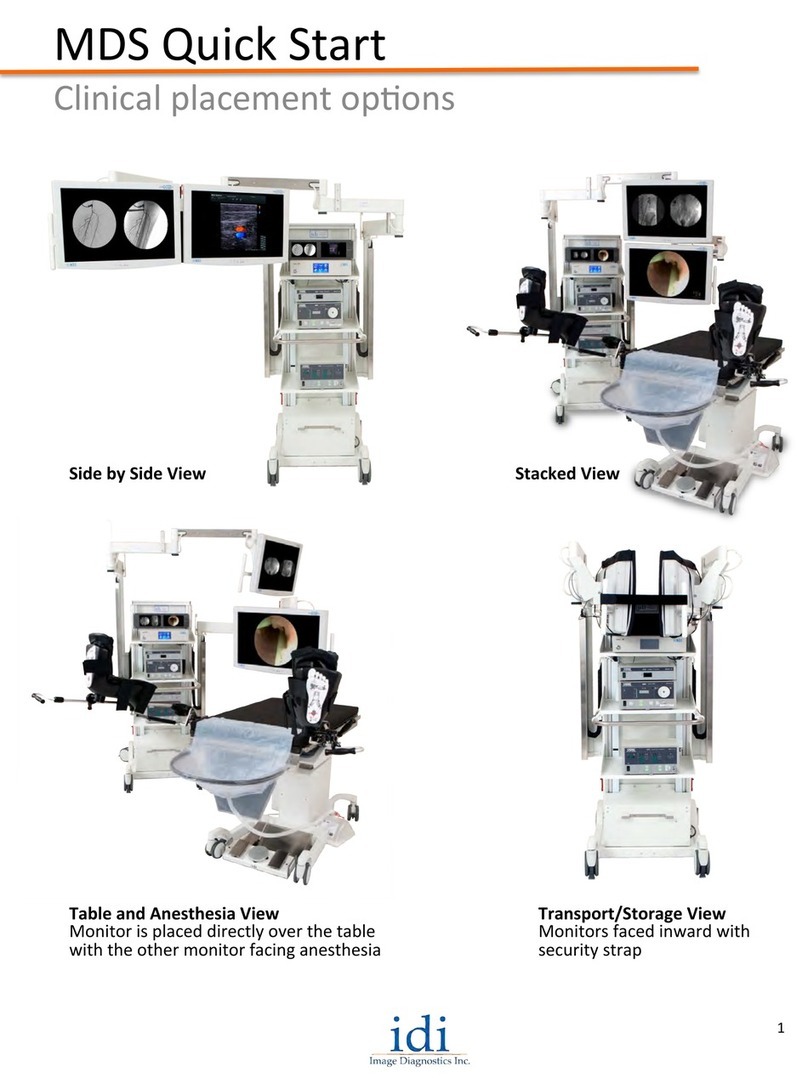
The MDS (Mobile Display System) is a mobile solution for video display and image
management. This system features flexibility with its video display positioning
combined with video signal routing and multiple image management options. The
MDS is designed to configure and control images from C-arm fluoroscopy, endoscopy,
patient monitoring, etc.
3. SAFETY INSTRUCTIONS
✓All persons using this equipment must fully understand its operation instructions,
emergency procedures, capabilities including total range of motion and be aware of
all potential safety hazards.
✓This manual should be accessible to all personnel installing, operating, or servicing
this equipment.
✓Only a qualified technician may install or service this equipment.
Failure to follow safety precautions may result in serious injury to patient or
user or damage to equipment.
Comments and questions regarding safety should be addressed to:
Customer Support
Image Diagnostics, Inc.
310 Authority Drive
Fitchburg, MA 01420 USA
Or call IDI at (978) 829-0009 or Toll Free (877) 304-5434.
The fax number for IDI is (978) 829-0027.
Review the SAFETY HAZARDS and OPERATING
INSTRUCTIONS before operating MDS

Installation & Operator Manual for MDS
L280-0960 Rev. C www.imagediagnostics.com 3
4. SAFETY HAZARDS
It is imperative that all personnel operating the MDS be familiar with the
equipment’s operation, transport and all documentation supplied by IDI. The
MDS system is intended to be used in typical clinical or research environments
in accordance with national medical standards. When transporting the MDS
from room to room, it is imperative that the device be moved while in its storage
configuration with the security strap in place and the arms folded into the unit so
that the magnetic stops are engaged. The MDS should be plugged into the
appropriate medical grade electrical outlet, not to exceed the rated amp values
as stated on the MDS serial number label.
Safety Hazard Level
Potential Consequences with Use
DANGER
Indicates an imminently hazardous situation which, if not
avoided, will result in death or serious injury.
WARNING
Indicates a potentially hazardous situation which, if not
avoided, could result in death or serious injury.
CAUTION
Indicates a potentiallyhazardous situation which, if not
avoided, may result in minor or moderate injury or
equipment damage.
WARNING!
Do not modify this equipment without authorization
of the manufacturer.
WARNING!
Do not jump any curbs or steps over 3/8” in height
with this equipment. Approach all obstacles slowly.
Operator must use a ramp to allow the casters to roll
up and over the vertical edge.
WARNING!
It is the user’s responsibility to make sure the
equipment is safe and operates properly prior to use.

Installation & Operator Manual for MDS
L280-0960 Rev. C www.imagediagnostics.com 4
CAUTION
Do NOT store liquids on the unit above any electrical
devices.
CAUTION
Confirm that the monitor arm heights are appropriate
for the clinical application, otherwise store in
transportation mode.
CAUTION
Injury may occur if the operator inadvertently runs into
the extended monitor arms. Be aware of the arm’s
location at all times during the installation and while in
use.
CAUTION
Prior to each clinical placement, confirm that there is no
vertical drift on the horizontal arms and that the swivel
and tilt mechanisms are functioning correctly.
CAUTION
If upper Locking Collars are loose, they may
inadvertently drop and prevent free vertical arm
movement.
CAUTION
Caution should be used when moving the system over
uneven or sloped surfaces.

Installation & Operator Manual for MDS
L280-0960 Rev. C www.imagediagnostics.com 5
5. EMC (Electromagnetic Compatibility) STATEMENT
Portable and Mobile RF Communications Equipment can affect Medical Electrical
Equipment including the ones used with the MDS.Use special precautions regarding EMC when
these Mobile Display Systems are installed, operated and maintained.
The use of accessories, transducers and/or cables other than those specified, with the
exception of those sold by the manufacturer as replacement parts for internal components, may
result in increased emissions or decreased immunity of the equipment or system.
WARNING: If MDS is used adjacent to or stacked with other medical electrical
equipment, the equipment and the MDS should be observed to verify normal
operation in the configuration in which it will be used.
NOTE: The emissions characteristics of this equipment make it suitable for use in
industrial areas and hospitals (CISPR 11 class A). If it is used in a residential environment (for
which CISPR 11 class B is normally required) this equipment might not offer adequate protection
to radio-frequency communication services. The user might need to take mitigation measures,
such as relocating or re-orienting the equipment.

Installation & Operator Manual for MDS
L280-0960 Rev. C www.imagediagnostics.com 6
6. INSTALLATION INSTRUCTIONS
Scope:
This section describes the process of preparing the MDS for Video Integration.
The MDS monitor arms are counter-balanced with a series of steel plates (behind
the rear cover) that are sized to accommodate the weight of a variety of medical
monitors. Each MDS system is factory balanced to the specifications based on
the weight of the Monitors supplied with the system. The Monitors are removed
for shipment and the weights are secured in place via upper and lower Locking
Collars.
Note: The upper and lower Locking Collars are used to secure the arms for shipping only.
After relocating the Collars, the Vertical Travel Lock Hooks should
ONLY be utilized during transportation of the unit.
Note: The original factory balance weight is noted on the face of the VESA Monitor
Support Bracket and the Face Balance Plates. If Monitors are upgraded to
smaller or larger sizes, it will be necessary to rebalance the Monitor Arms
with the new monitor weight. Additional plates can be ordered from IDI if
needed. Please contact customer service prior to changing Monitors. It is
recommended that two persons assist in the mounting/un-mounting of
Monitors.
WARNING!
Loosening the Shipping Locking Collars without the
monitors being installed will create a severe
imbalance and uncontrolled rapid arm movement!
CAUTION!
When mounting or removing the monitors, confirm
that the vertical travel lock is engaged and the
upper/lower collar locks are secured.
WARNING!
The mounted monitors can be considered as
suspended mass which can fall and cause injury if
they are not properly mounted.

Installation & Operator Manual for MDS
L280-0960 Rev. C www.imagediagnostics.com 7
6.1. Mount Two Main Monitors.
Tools: 5/32” Hex Key, Torqueing Phillips (Cross) Screwdriver, #222 Loctite and
Orange Torque Seal.
Procedure:
6.1.1. Using a 5/32” Hex Key, remove the MDS Back Panel by removing all the
upper and lower Socket Head Cap Screws.
6.1.2. Locate and confirm the upper and lower rail Locking Collars are secure and in
place against the top and bottom Counterweight Bracket Flanges as shown in
the photos below.
NOTE: The upper and lower Locking Collars are used to secure the Arms for shipping only,
and after they are relocated the Vertical Travel Lock Hooks should ONLY be utilized during
transportation of the unit.
6.1.3. Unpack the two main Monitors carefully and lay them face down on a
protective surface.
6.1.4. Locate and remove the four mounting screws on the back panel of the Monitor.
WARNING!
If the Locking Collars are found to be loose, secure with the Hex
Key before proceeding.

Installation & Operator Manual for MDS
L280-0960 Rev. C www.imagediagnostics.com 8
6.1.5. Apply #222 Loctite to two of the screws and partially install the upper two
screws as to allow enough of a gap below the screw heads so they can easily
slide into the top slots of the VESA mounting plates on the MDS arm while
still being able to support the weight of the Monitor. See photo below.
6.1.6. With assistance from another individual, lift the Monitor with the partially
installed upper screws and slide the screws into the upper slots of the VESA
Mounting Plates on the MDS arm.
6.1.7. Apply #222 Loctite to the two remaining screws and install them into the
bottom holes of the VESA Mounting Plates on the MDS arm. Torque all four
screws to 23lbf-in. (2.6N-m).
6.1.8. Apply orange torque seal to the heads of the four monitor mounting screws.
6.1.9. Connect the power cable and the video cable to the appropriate port input.
6.1.10. Repeat steps 6.1.2 through 6.1.9 with the second Monitor.

Installation & Operator Manual for MDS
L280-0960 Rev. C www.imagediagnostics.com 9
6.2. Release Monitor Counterbalance
Tools: 3/16” Hex Key.
Procedure:
6.2.1. Once both main Monitors are mounted and secure, the counterweight Locking
Collars are ready to be relocated from their storage positions.
6.2.2. With a 3/16” Hex Key, loosen the lower Locking Collars and lower them to the
bottom of the slide rail. Loosen and raise the upper Locking Collars to the top
of each slide rail and retighten as shown below.
NOTE: Arms will not move vertically until Vertical Travel Lock Hooks are disengaged.

Installation & Operator Manual for MDS
L280-0960 Rev. C www.imagediagnostics.com 10
6.2.3. Release the red Vertical Travel Lock Hooks shown below and each monitor
arm should lower and raise with minimal physical effort.
6.2.4. If the monitor arms drift up or down easily or drift in one direction or another,
the unit may need to be rebalanced. Contact IDI Customer Service for
procedure steps.
NOTE: There are inner and outer locking collars for each balance plate.
6.3. Shelf Adjustment
Tools: 3/16” Hex Key, a Level and an assistant.
Procedure:
6.3.1. Remove all devices off the Shelf that is to be repositioned.
6.3.2. Have an assistant hold onto the sides of the Shelf to be moved.
6.3.3. Using a 3/16” Hex Key, loosen the Button Head Socket Screws (2 on each side
of Shelf) just to the point where it can rotate freely but DO NOT remove.
6.3.4. The assistant can now slide the Shelf up or down to a desired location.
VERTICAL
TRAVEL
LOCK HOOK

Installation & Operator Manual for MDS
L280-0960 Rev. C www.imagediagnostics.com 11
6.3.5. Using a Level, measure the Shelf to ensure that it is level and then re-tighten
all four Screws.
6.3.6. Replace Devices onto the shelf and tuck power or video cords into the side
Channels of the Cart or wrap around cable hooks provided on sides of second
shelf from the bottom.
6.4. Clean Unit
Tools: Soft Cloth and one of the following Approved Cleaners:
oSodium hypochlorite (generic household bleach) in a solution of 5.25%
sodium hypochlorite diluted between 1:10 and 1:100 with water.
oAlcohol (generic).
oEnvirocide®
Procedure:
6.4.1. Unplug the MDS system prior to cleaning the unit.
6.4.2. Wipe clean the surfaces of the MDS system with a diluted mixture of mild
detergent (listed above) and water using a soft cloth.
NOTE: For cleaning Video Routers and Monitors, please consult corresponding literature for
these devices. NEVER use alcohol to clean the monitors.
6.5. Electronics Installation
Procedure:
6.5.1. All electronic devices are to be installed according to their perspective
manufacturer’s IFU (Information for use) documenation.

Installation & Operator Manual for MDS
L280-0960 Rev. C www.imagediagnostics.com 12
7.1. Moving the MDS Unit
Tools: Security Strap and an assistant.
Procedure:
7.1.1. Lower both Arms of the MDS Unit to a comfortable height to ease in the
installation of Monitor covers.
7.1.2. Fold the Arms into themselves so that the
stainless-steel Covers are facing towards the
outside as shown to the right.
7.1.3. The MDS arms are equipped with rotational stops
with built in magnets that help prevent
inadvertent arm movement. Confirm that Arms
are pushed in and Magnets are engaged.
7.1.4. Lift the arms so that the base of the monitor
clears the upper most Device placed on the Top
Shelf and rotate the face of one of the Monitors
inward and gently lower the Monitor on to the
top shelf. Repeat the process for the other
Monitor.
7.1.5. With both Monitors facing inward, place the
Security Strap over the top of each Monitor
Handle as shown to the right and secure snugly.
7. OPERATOR INSTRUCTIONS
WARNING!
Always use a minimum of two persons while
transporting the MDS unit to aid in maneuverability
and to aid with visibility.
CAUTION!
The user should confirm that the arms are folded in
as far as possible, and the magnets are engaged, in
order to prevent unintended arm swing.

Installation & Operator Manual for MDS
L280-0960 Rev. C www.imagediagnostics.com 13
7.1.6. Disengage caster motion locks on all four casters by
pushing up on caster lock levers with top of foot as
shown on the right.
7.1.7. MDS unit can now be transported by two
individuals using the handles located on the sides
and back to maneuver the unit.
7.1.8. Once the MDS unit is relocated to its final position,
all four casters should be motion locked by stepping
down on the caster lock pedal until they are fully
engaged.
7.2. Moving Monitor Positions
Procedure:
7.2.1. To move monitor position, grab the monitor handle just below the monitor.
7.2.2. Push and pull monitor to desired location within the limits of the articulating
arms they are mounted to.
7.2.3. To tilt monitor position downward, hold the top of the monitor mount and push
the monitor handle away from the operator.
7.2.4. To tilt monitor position upward, hold the top of the monitor mount and pull the
monitor handle away toward the operator.
7.2.5. To raise the monitor position, grab the monitor handle and push upward.
7.2.6. To lower monitor position, grab the monitor handle and pull downward.
CAUTION!
Vertical travel of monitor is counterbalanced, so
there should be no excessive force required to
move monitors up and down. If excessive force is
required, please check that the transport lock
brake is unlatched and if this does not resolve the
issue please contact IDI service for further
troubleshooting.

Installation & Operator Manual for MDS
L280-0960 Rev. C www.imagediagnostics.com 14
All maintenance procedures should be done by an experienced and qualified technician with
demonstrated knowledge and skills (electrical and mechanical) in the service of medical
equipment.
✓This individual must have access to this manual and the proper tools.
✓Lubrication of this device is not required.
8.1. Recommended Periodic Performance Checks
Daily
Inspect all external cables and electrical
components for wear and damage.
Damaged cables must be replaced
promptly. The MDS uses a medical
grade power cord which is not user
serviceable. Replacement must be
performed only by a qualified service
technician.
Weekly
Move the monitors through their full
range of motion to verify that they are
not worn or damaged.
8. MAINTENANCE, SERVICE & REPAIR

Installation & Operator Manual for MDS
L280-0960 Rev. C www.imagediagnostics.com 15
8.2. Service & Repair Statement
Only qualified personnel should perform repairs on this equipment. Please read this
entire document before performing any diagnostics or repairs. Some procedures listed
require this device to be energized while repairs are performed; please exercise
extreme caution while working with electrical components. Always exercise
appropriate lockout/tag out procedure while performing any diagnostics and service
on the unit.
9. TROUBLESHOOTING
Problem/Symptom
Possible Cause
Remedy
1. MDS generates
or receives electrical
interference.
1. Incompatibility.
1. Verify that the equipment is the
cause by turning the system or
individual components off and on.
2. Use only high quality cables to avoid
electrical noise.
10. DISPOSAL OF COMPONENTS
The IDI MDS base and arms are made up of mostly steel and aluminum
parts which are easily recycled. The casters are made of mostly plastic.
It is recommended that some components be disassembled before
disposal for recycling.

Installation & Operator Manual for MDS
L280-0960 Rev. C www.imagediagnostics.com 16
11. SPECIFICATIONS/PRODUCT DATA
Type of Equipment:
▪Class I (as defined by IEC 60601-1, 3rd Edition)
▪CENELEC EN 60601-1, ANSI/AAMI ES60601-1, and IEC 60601-1, 3rd Edition)
Electrical:
▪Supply Voltage:
120±5% Vac 60Hz through NEMA 5-15P hospital grade plug.
230±10% Vac 50Hz through country specific plug.
▪Output Voltage: 120 VAC 60Hz (1800VA) or 230 VAC 50Hz (1800VA).
▪Current Rating: Less than 12 Amps @ 120 Vac or 7 Amps @ 230 Vac.
▪Isolation transformer limits leakage current to 50μA.
▪Isolation transformer is certified to meet Medical Safety Standards ANSI/AAMI
ES60601-1.
Environmental:
▪Operating Temperature Range: 41F to 95F (5°C to 35°C)
▪Operating Humidity Range: 10% to 85% relative humidity, noncondensing.
▪Operating Pressure Range: 500 hPa to 1060 hPa.
▪Transport & Storage Temperature Range: 32F to 113F (0°C to 45°C).
▪Transport & Storage Humidity Range: 10% to 85% relative humidity, noncondensing.
▪Transport & Storage Pressure Range: 500 hPa to 1060 hPa.
Not suitable for oxygen rich environment.
Not suitable for flammable anesthetic mixtures.
Product Features Included With MDS:
▪Thermal protector AC input module.
▪Medical Grade output strip for Monitor & Ancillary power.
▪Individual cables for monitor power and video input.

Installation & Operator Manual for MDS
L280-0960 Rev. C www.imagediagnostics.com 17
12. WARRANTY
Warranty details for IDI Products can be obtained directly from Image Diagnostics, Inc.
Image Diagnostics, Inc.
310 Authority Drive
Fitchburg, MA 01420 USA
Or call IDI at (978) 829-0009 or Toll Free (877) 304-5434.
The fax number for IDI is (978) 829-0027.
Other manuals for MDS
1
Table of contents
Other idi Medical Equipment manuals

idi
idi Aspect 100-4T G3 User manual

idi
idi Aspect 100-4 Q-CARD User manual

idi
idi Aspect 100-4 Q-CARD User manual

idi
idi Aspect100US User manual

idi
idi Aspect ISO-Drive User manual

idi
idi MDS User manual

idi
idi Aspect100T User manual

idi
idi ilex User manual

idi
idi Aspect100UC Plus User manual

idi
idi Aspect Q-CARD 100-4T User manual

idi
idi ilex User manual

idi
idi Aspect ISR G3 User manual

idi
idi Aspect ISR G3 User manual

idi
idi 1000F Series Product manual

idi
idi Aspect 100RTL Q-CARD User manual

idi
idi Aspect 100UC Plus Q-CARD User manual

idi
idi Aspect100E User manual

idi
idi Aspect100-4 User manual

idi
idi Aspect Iso-Drive Q-CARD User manual

idi
idi Aspect 100-4 Q-CARD User manual