IKA ULTRA-TURRAX T 25 digital User manual

Operating instructions EN
T 25 digital ULTRA-TURRAX®

2
Item Designation
1Extension arm
2Hexagon socket screw
3Cross sleeve
4Disperser
5Stand
6Tensioner
7Dispersion tool
8Knurled screw
9On/Off-switch
10 Rotary knob „speed“
11 LED- Display speed
1
3
4
5
6
8
7
10
9
11
2
On Off
Filling level
min. 55 mm
Distance bottom/
disperding tool
10 mm
!
Fig. 1
!
Fig. 2
Points should be watched out for!

3
Source language: German EN
Contents
EU Declaration of conformity
Page
EU Declaration of conformity 3
Explication of warning symbols 3
Safety instructions 3
Unpacking 5
Correct use 5
Useful information 5
Drive 6
Assembly of boom and stand 6
Working with the unit 6
Maintenance and cleaning 7
Accessories 7
Permitted dispersion tools 7
Error codes 8
Warranty 8
Technical data 9
We declare under our sole responsibility that this product corresponds to the directives 2014/35/EU, 2006/42/EC, 2014/30/EU
and 2011/65/EU and conforms with the standards or standardized documents EN 61010-1, EN 61010-2-051, EN 61326-1,
EN ISO 12100 and EN 60529.
A copy of the complete EU Declaration of conformity or further declarations of conformity can be requested at [email protected].
Safety instructions
For your protection:
•Read the operating instructions in full before start-
ing up and follow the safety instructions.
• Keep the operating instructions in a place where they can
be accessed by everyone.
• Ensure that only trained staff work with the appliance.
• Follow the safety instructions, guidelines, occupational
health and safety and accident prevention regulations.
Explication of warning symbols
Indicates an (extremely) hazardous situation, which, if not avoided, will result in death,
serious injury.
Indicates a hazardous situation, which, if not avoided, can result in death, serious injury.
Indicates a potentially hazardous situation, which, if not avoided, can result in injury.
Indicates practices which, if not avoided, can result in equipment damage.
WARNING
CAUTION
NOTICE
DANGER

4
Wear your personal protective
equipment in accordance with the
hazard category of the media to be
processed. Otherwise there is a risk from:
- splashing and evaporation of liquids
- body parts, hair, clothing and jewellery getting caught.
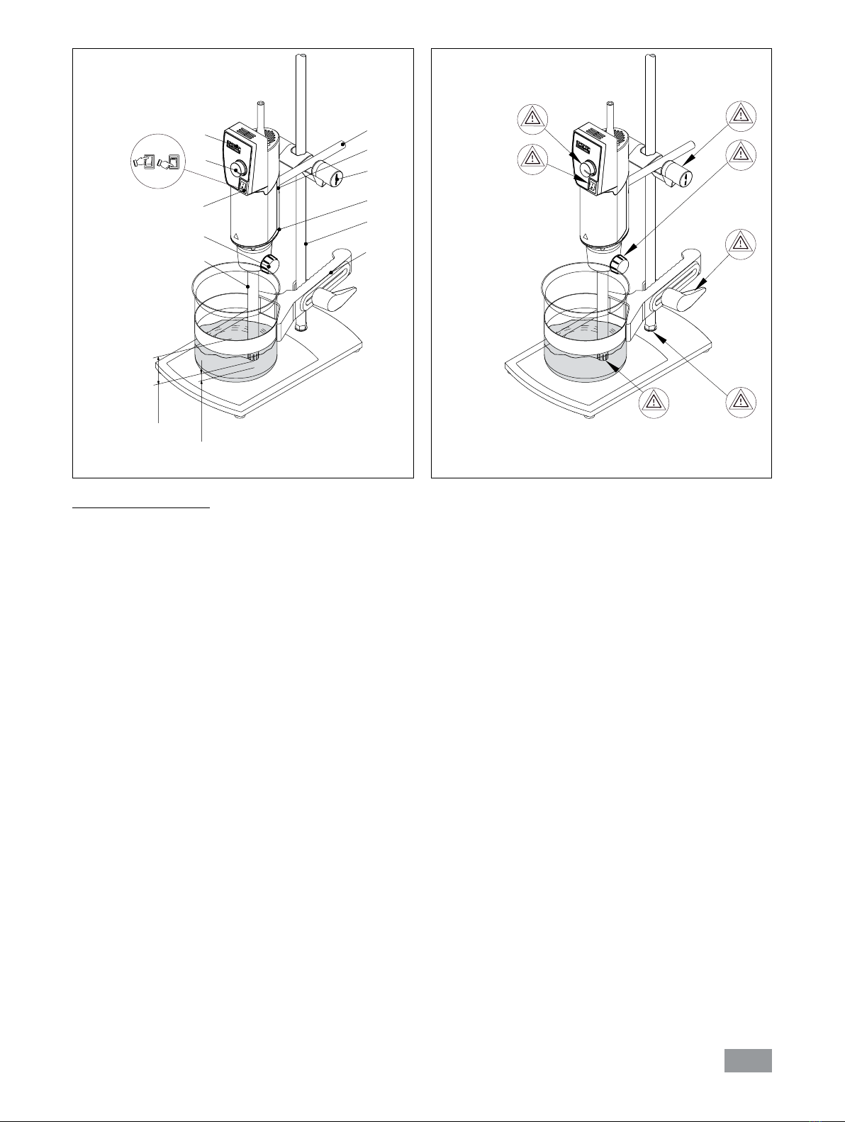
• Set up the stand in a spacious area on an even, stable,
clean, non-slip, dry and fireproof surface.
• Check the appliance and accessories beforehand for dam-
age each time you use them. Do not use damaged com-
ponents.
• The appliance is not suitable for manual operation.
• The agitation vessels used for dispersing have to be se-
cured. Consider on a good stability of the entire structure.
• Secure the agitation vessel against twisting.
• Check that the turning knobs are secure and tighten if
necessary.
• Glass vessels must always be secured with a clamp to
prevent them spinning. When working with flasks elastic
couplers must be used to prevent fracture of the glass.
• Note the operating instructions of the dispersing tool and
accessories.
• Only dispersing elements approved by IKA may be used.
• Please observe the permitted speed for the dispersing ele-
ment. Never set higher speeds.
• Do not use the appliance without a dispersing element.
• Use the dispersing tool always inside the stirring vessel.
• Never run dispersion tools dry, as the gasket and bearings
will be destroyed if the tools are not cooled by the medium.
If a dispersing element is not insert-
ed into the drive flange as far as the
mark it can become extremely hot
in operation and thus suffer damage.
• Make certain that the unit is set at the lowest speed be-
fore commissioning; otherwise, the unit will begin run-
ning at the speed last set. Gradually increase the speed.
• Reduce the speed if the medium splashes out of the vessel
because the speed is too high.
•
Before switching on the dispersing instrument make sure
that its shaft is immersed min. 45 mm in the medium to
prevent the medium from splashing out.
•
The distance between the dispersion tool and the vessel bot-
tom should not be less than 10 mm.
• Ensure that the stand does not start to move.
•
In the event of unbalance or unusual noises, switch off the
appliance immediately. Replace the dispersing element. If
there is no difference after the change of the dispersing
tool, return it to the dealer or the manufacturer along with
a description of the fault.
Do not touch rotating parts during op-
eration.
• When in operation, the dispersing element and the cou-
pling flange can become hot.
WARNING
NOTICE
DANGER
DANGER
DANGER
• Do not cover the ventilation slots on the drive in order to
ensure adequate cooling of the drive.
Beware of the risk of:
- flammable materials
- glass breakage
- sharp edges on the dispersing tool.
• Process pathogenic materials only in closed vessels under
a suitable extractor hood. Please contact IKA if you have
any questions.
Do not use the device in explosive
atmospheres, it is not EX-protected.
With substances capable of forming an explosive mixture,
appropriate safety measures must be applied, e.g. work-
ing under a fume hood.
To avoid body injury and property damage, observe the rele-
vant safety and accident prevention measures when process-
ing hazardous materials.
Only process media that will not react dangerously to the
extra energy produced through processing. This also ap-
plies to any extra energy produced in other ways, e.g.
through light irradiation.
• There may be electrostatic discharges between the medi-
um and the dispersing instrument shaft which could pose
a direct danger.
• Only process media that will not react dangerously to the
extra energy produced through processing. This also ap-
plies to any extra energy produced in other ways, e.g.
through light irradiation.
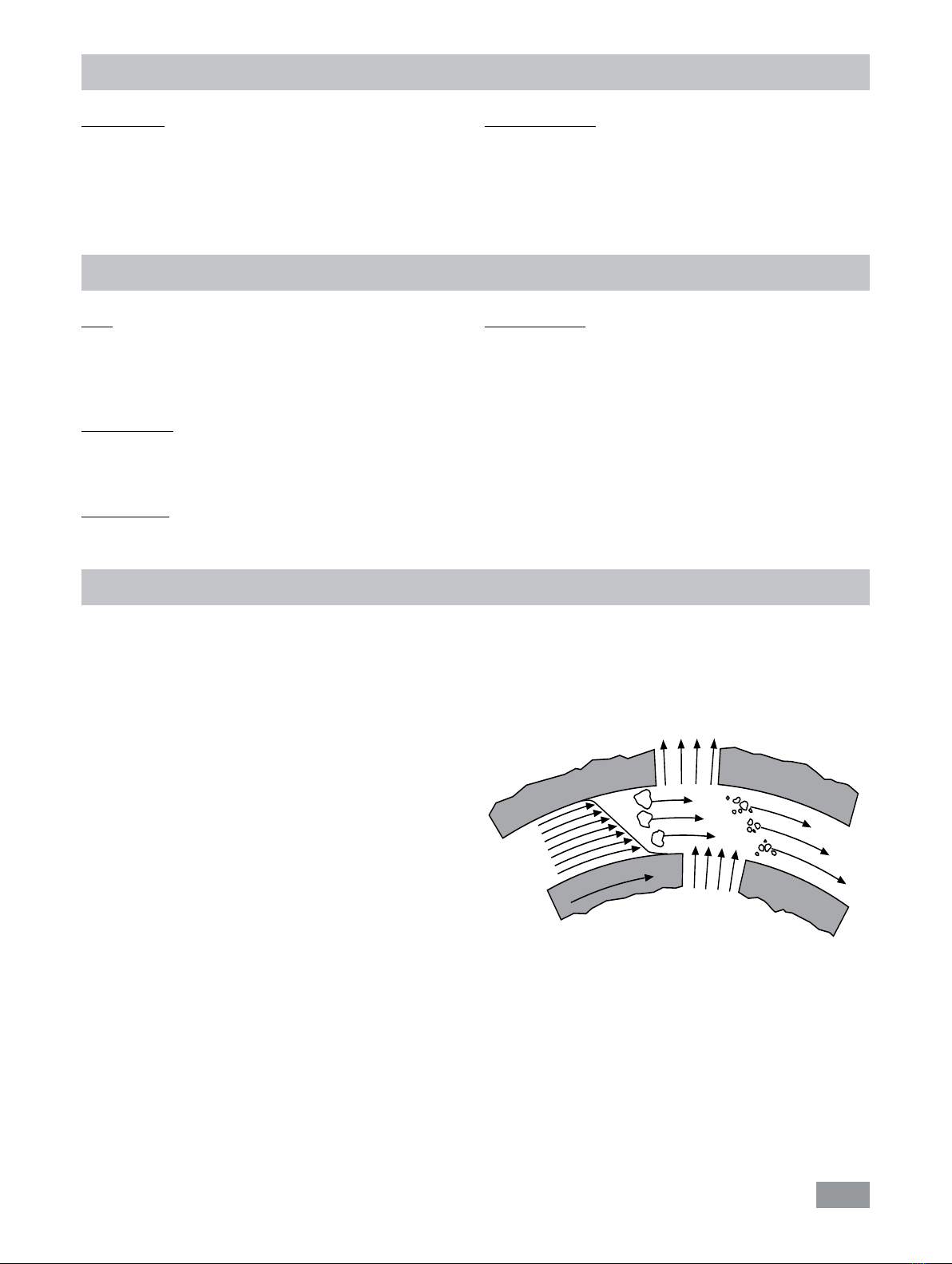
• Meter powder not too close to the flange. Powder can be
blown away by air turbulences of the drive.
•
Safe operation is only guaranteed with the accessories de-
scribed in the ”Accessories” chapter.
• Always disconnect the plug before fitting accessories.
• The appliance can only be disconnected from the mains
supply by pulling out the mains plug or the connector plug.
• The socket for the mains cord must be easily accessible.
• The appliance does not start up again automatically fol-
lowing a cut in the power supply.
• Abrasion of the dispersion equipment or the rotating ac-
cessories can get into the medium you are working on.
For protection of the equipment:
• The appliance may only be opened by experts.
• The voltage stated on the type plate must correspond to
the mains voltage.
• Removable parts must be refitted to the appliance to pre-
vent the infiltration of foreign objects, liquids etc..
• Protect the appliance and accessories from bumps and
impacts.

5
Unpacking:
- Please unpack the device carefully.
- In the case of any damage a fact report must be sent im-
mediately (post, rail or forwarder).
Delivery scope:
- T 25 digital ULTRA-TURRAX®
- Extension arm
- Hexagon socket screw
- Screwdriver DIN 911
- User guide.
Useful information
Unpacking
Dispersion is the dissolution and diffusion of a solid, liquid
or gaseous phase in a liquid that is not consolute with that
phase.
The rotor/stator principle:
Due to the high rotation speed of the rotor, the medium
to be processed is automatically drawn axially into the dis-
persion head and then forced radially through the slots in
the rotor/stator arrangement. The high accelerations acting
on the material produce extremely strong shear and thrust
forces. In addition, high turbulence occurs in the shear gap
between rotor and stator, which provides optimum mixing
of the suspension.
The dispersion effectiveness is heavily dependent on the
product of the shear gradient and the time the particles
spend in the shear zone. The optimum range for the circum-
ferential velocity of the rotor/stator arrangement is 6-24 m/s.
RO
TO
R
ST
AT
OR
Fig. 3
A processing time of a few minutes is usually sucient to
produce the desired fineness. Long processing times bring
only insignificant improvements in the obtainable fineness;
the energy expended serves merely to increase the tempera-
ture of the medium.
Use:
When used in combination with one of our recommended
dispersion tools, the drive unit is a high-speed dispersing
and emulsifying unit capable of handling free-flowing and
liquid media in batches.
Production of:
Emulsions
Dispersions
Wet crushing
Intended use:
On stand (dispersing tool points down)
Range of use:
Indoor environments similar to that a laboratory of industry
area.
The safety of the user cannot be guaranteed:
- If the device is operated with accessories that are not sup-
plied or recommended by the manufacturer
- If the device is operated improperly or contrary to the
manufacturer’s specifications
- If the device or the printed circuit board are modified by
third parties.
Intended use

6
Caution: Burns hazard! If a dispersing element is not in-
serted into the drive flange as far as the mark it can become
extremely hot in operation and thus suffer damage.
So as to avoid unintentional ingress of air into the medium
due to excessively turbulent rotation, the whole unit can be
placed a little off center in the stirring vessel.
By using the turning knob (
item
10) the speed may be in-
finitely varied to meet the requirements of the medium to be
processed.
The idle speed for the drive unit can be adjusted in the
range 3000 – 25000 rpm; the value will be shown on the
LED display.
If these conditions are met the unit is
ready for service when the mains plug
has been plugged in.
The driving unit is switched on by means of the On/Off-
switch (item 9).
The speed is set by using the differently adjusting wheel.
The motor speed can be read off the LED display. For exam-
ple, a value of 13.6 corresponds to 13600 rpm.
The drive unit opens up a wide range of possibilities for dis-
persion technology in the conventional laboratory with a
respective performance output of approximately 500 watts
at 25000 rpm.
To ensure safe operation the driving unit is fastened to the
plate stand R 1826 (
item
5) by means of a cross sleeve (
item
3).
In order to enhance the stability of the mechanical arrange-
ment, the driving unit has to be mounted as close as possi-
ble to the stand pillar.
The delivered extension arm is mounted as follows (over-
view fig. 1):
• Insert extension arm (item 1) into flange
• Screw in the cheese head screw (item 2)
•
Firmly tighten cheese head screw (
item
2) using the DIN 911
A/f 4 screwdriver
Vibrations may cause the cylinder head screw (item 2) to
loosen. Therefore, for your own safety, periodically check
that the extension arm is secure. If necessary, re-tighten the
cylinder head screw (item 2).
Drive
Assembly of boom and stand
0 mm
!
!
1
3
2
2
Fig. 4
Working with the unit
Also pay attention to the ambient conditions listed in the
“Technical data”.
Assembling the dispersion tool:
(Overview Fig. 5)
- Open the knurled screw (item 3) so that the thread does
not protrude into the hole.
- Insert the dispersing element (item 2) from the bottom into
the drive unit (item 1) as far as the stop.
The shaft will audi-
bly click into place when a small amount of force is applied
(sprung ball bearing) - depending on the type of disperser.
The dispersing element is fitted correctly if the dispersing
element is flush with the bottom edge of the drive unit.
- Attention: Now secure the dispersing element by screw-
ing the knurled screw tight (item 3).

7
Spare parts order:
When ordering spare parts, please give:
- Machine type
- Serial number, see type plate
- Item and designation of the spare part,
see www.ika.com, spare parts diagram and spare parts list
Repair:
In case of repair the device has to be cleaned and
free from any materials which may constitute a health
hazard.
For this use the "Decontamination Certificate" or down-
load the form from the IKA website www.ika.com.
If you require servicing, return the appliance in its original
packaging.
Storage packaging is not sufficient. Please also use suitable
transport packaging.
The drive unit is maintenance-free but not immune from wear.
The motor brushes and the coupling wear out over time.
Cleaning:
For cleaning disconnect the main plug.
To clean the drive use only water with a water (containing
surfactant) or use isopropyl alcohol for stubborn soiling (not
for plastic parts).
Dispersion tools: Consider place the manuals associated to
the dispersion tools.
- Do not allow moisture to get into the appliance when
cleaning.
- Wear protective gloves when cleaning the devices.
-
Please consult with IKA before using any cleaning or decon-
tamination methods, other than those recommended here.
Maintenance and cleaning
Accessories
• R 1825 Plate stand
• R 1826 Plate stand
• R 1827 Plate stand
• R 182 Cross sleeve
• RH 3 Tensioner
See more accessories on www.ika.com.
See more permitted dispersion tools on www.ika.com.
Permitted dispersion tools
Dispersing tools serie S 25...
Abbreviations:
S 25: consistent with dispersing unit T 25
N: PTFE bearing
NK: Ball bearing with PTFE bearing
KV: Ball bearing with axial face seal (suitable for vacuum
up to 1 mbar, 6 bar excess pressure)
D: Without seal
KS: Synthetic material
8G, 10G, 18G, 19G, 25G, 25F :
Stator/shaft tube diameter
G: Coarse
F: Fine
Speed range: upto 25000 rpm
For applications and further information, please see the op-
erating instructions of the dispersing tool.
Only use the dispersion tools listed in the table and
note the according operating instructions of the dis-
persion tool.
Designation Shaft material
S25N-8G Stainless steel
S25N-10G Stainless steel
S25N-18G Stainless steel
S25KV-18G Stainless steel
S25NK-19G Stainless steel
S25N-25G Stainless steel
S25KV-25G Stainless steel
S25N-25F Stainless steel
S25KV-25F Stainless steel
S25D-10G-KS Synthetic material
S25D-14G-KS Synthetic material

8
Error codes
Proceed as follows in case of error:
Switch off device using the main switch.
Carry out corrective measures.
Restart the device.
Error code Cause Effect Solution
Er. 3 Overtemperature
Device will switch automatically to
cooling mode if operated with excess
load
Motor
speed set
automatically
(not adjustable)
- Allow device to cool down.
- Allow to continue running in cooling mode.
- Switch device off. Switch on again after some time.
(Duration depends on the magnitude of the
overtempertature)
Er. 4 Speed variation
Speed variation due to blockage, faulty
electronics, overload, motor brushes worn
Device off - Switch off device
- Eliminate cause of overload or blockage (remove
dispersing element)
- Replace motor brushes
- Switch on device
- If the actions described fail to resolve the fault, contact
the IKA service department.
Send the device for repair, including a short description
of the fault.
Er. 6*Undervoltage
Mains voltage failed during operation
Plug in the mains plug if the switch
position is "ON"
Device off
Device off
- Switch device off and on.
*Before Er. 6 is displayed the software version is shown for approx. two seconds, e.g. 00.9.
If the actions described fail to resolve the fault or another error code is displayed then take one of the following steps:
- Contact the IKA service department
- Send the device for repair, including a short description of the fault.
Warranty
In accordance with IKA warranty conditions, the warranty
period is 24 months. For claims under the warranty please
contact your local dealer. You may also send the machine
direct to our factory, enclosing the delivery invoice and giv-
ing reasons for the claim. You will be liable for freight costs.
The warranty does not cover worn out parts, nor does it
apply to faults resulting from improper use, insucient care
or maintenance not carried out in accordance with the in-
structions in this operating manual.

9
Technical data
Design voltage VAC 220 ... 240 ± 10 %
100 ... 120 ± 10 %
Nominal voltage VAC 230
115
Frequence Hz 50 / 60
Power consumption W800
Power output W500
Speed range rpm 3000 ... 25000
(at nominal voltage 230V / 50Hz and 115V / 60 Hz)
Speed variation on load change %< 1
Motor speed display 3-digit LED display, displayed value x 1000 = motor speed in rpm
Display resolution rpm 200
Permissible ambient conditions 5 °C to 31 °C at 80 % relative humidity.
32 °C to 40 °C decreasing linearly to a maximum 50 % relative humidity.
Permissible on time %100
Protection to DIN EN 60529 IP 20
Contamination level 2
Protection class II
Overvoltage category II
Noise level (without dispersing tool)
dbA 75
Dimensions drive (W x D x H) mm 87 x 106 x 271
Dimensions boom (Ø x L) mm 13 x 160
Weight kg 2.5
Operation at a terrestrial altitude mmax. 2000
Subject to technical changes!

20000027553a_EN_T25 digital_032023_web
Technical specifications may be changed without prior notice.
IKAworldwide IKAworldwide /// #lookattheblue @IKAworldwide
Discover and order the fascinating products of IKA online:
www.ika.com
JAPAN
IKA Japan K.K.
Phone: +81 6 6730 6781
eMail: [email protected]
INDIA
IKA India Private Limited
Phone: +91 80 26253 900
eMail: [email protected]
UNITED KINGDOM
IKA England LTD.
Phone: +44 1865 986 162
eMail: [email protected]
MALAYSIA
IKA Works (Asia) Sdn Bhd
Phone: +60 3 6099-5666
eMail: [email protected]
CHINA
IKA Works Guangzhou
Phone: +86 20 8222 6771
eMail: [email protected]
POLAND
IKA Poland Sp. z o.o.
Phone: +48 22 201 99 79
eMail: [email protected]
USA
IKA Works, Inc.
Phone: +1 910 452-7059
eMail: [email protected]
KOREA
IKA Korea Ltd.
Phone: +82 2 2136 6800
eMail: [email protected]
BRAZIL
IKA Brazil
Phone: +55 19 3772 9600
eMail: [email protected]
IKA-Werke GmbH & Co. KG
Janke & Kunkel-Straße 10, 79219 Staufen, Germany
Phone: +49 7633 831-0, Fax: +49 7633 831-98
eMail: [email protected]
VIETNAM
IKA Vietnam Company Limited
Phone: +84 28 38202142
eMail: [email protected]
THAILAND
IKA Works (Thailand) Co. Ltd.
Phone: +66 2059 4690
eMail: [email protected]
TURKEY
IKA Turkey A.Ş.
Phone: +90 216 394 43 43
eMail: [email protected]
Table of contents
Other IKA Laboratory Equipment manuals
Popular Laboratory Equipment manuals by other brands

cytiva
cytiva ReadyToProcess Mixer 20/50 operating instructions

Markes International
Markes International Kori-xr installation manual

W&H Med
W&H Med Lisa VA131-17 Instructions for use

Gerhardt
Gerhardt Vapodest 30 instruction manual

Labconco
Labconco Protector Echo 180 Series user manual

BRIGHT
BRIGHT OTF6000 manual