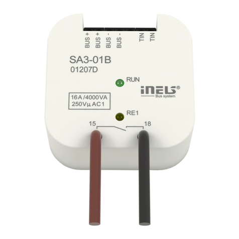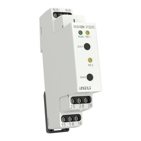
SA3-012M
Switching actuator 12-fold
EN
1/2
Characteristics /
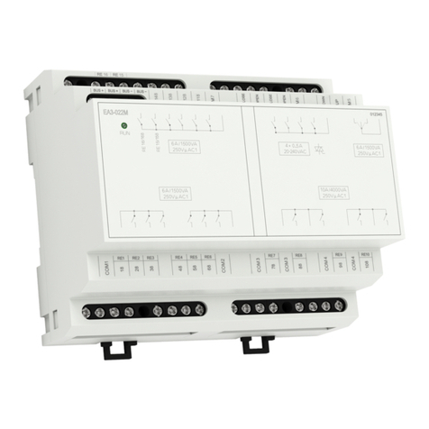
- The actuator is designed for switching to twelve various appliances and loads with potentialless
contact.
- SA3-012M is a switching actuator containing 12 independent relays with NO potentialless con-
tacts, with the fact that switches the same potential.
- Maximal loadability of contacts is 8 A/2000 VA/AC1.
- Each of the twelve output contacts are individually controllable and addressable.
- Actuator SA3-012M is powered by an AC voltage 230V. The unit SA3-012M/120V is powered by
AC voltage 120V AC.
- BUS is galvanically separated from the internal circuits of unit.
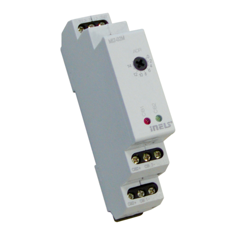
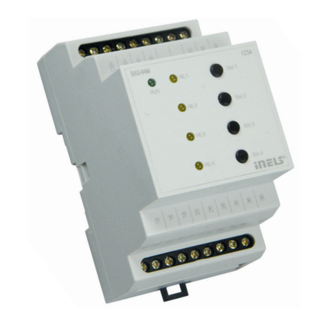
- LED on front panel signalizes state of each output.
- Contact status of each relay can be changed separately and manually by control buttons on a
front panel.
- SA3-012M is normally supplied in the option AgSnO2contact material.
- SA3-012M in design 6-MODULE is designed to be mounted into a switchboard, onto DIN rail
EN60715.
General instrucions /
CONNECTION INTO THE SYSTEM
Connect the product to the system according to the connection diagram listed with each prod-
uct. The wires of data BUS of iNELS system are connected to the terminals BUS + (standard red
wire for single-pair wiring, red and yellow for two-pair wiring) and BUS- (standard black wire for
single-pair wiring, black and white for two-pair wiring), and it is not possible to change the termi-
nals. A twisted pair of wires must be used for the data BUS with a wire diameter at least 0.8 mm.
Data communications and power supply to the units are led in a single pair of wires, and you must
observe the power cable size with regard to voltage loss on the wire and the maximum power
draw. Powering the device is provided by connection to the mains voltage AC 230 V to terminals L
and N. The product must remain connected to the mains voltage at all times.
CAPACITY AND CENTRAL UNIT
It is possible to connect to the central unit CU3-01M or CU3-02M two independent BUSes BUS
by means of terminals BUS1+, BUS1- and BUS2+, BUS2-. It is possible to connect to each BUS up to
32 units, so it is possible to connect directly to the central unit a total of 64 units. It is necessary
to comply with the requirement of a maximum load of one BUS line – maximum up to 1000mA
current. It is the sum of the rated currents of the units connected to the BUS line, other units can
be connected using the units MI3-02M, which generate further BUSes BUS. These are connected
to the CU3 unit via the system BUS EBM and you can connect a total of 8 units via EBM BUS to the
central unit MI3-02M .
COMMUNICATION BUS OF THE SYSTEM
The bus must have a cable created by a twisted pair of wires for data BUS of the system with a mini-
mum wire diameter of 0.8 mm. A shielded cable must be used in case of installation of cables of
the BUS in an environment with the possibility of electromagnetic interference (e.g. when running
along power lines, near electric machines and devices, during LV passage through a distributor,
etc.). We highly recommend using the cable JYSTY 2x2x0,8 for BUS. The BUS cable is installed in
accordance with its mechanical properties given by the producer (into a pipe/bar, under plaster,
underground, suspended, etc.) To increase the mechanical resistance of cables, we always recom-
mend installing the cable into an electrical insulation pipe of the appropriate diameter. The total
length of wires of the BUS for CU3-01M (CU3-02M), or MI3-02M, can be 1,100 m (550 m for each
BUS). The topology of the communications BUS is open with the exception of topology of the
circuit. It is necessary to use the cable FTP CAT5e or higher for the system BUS EBM – one pair of
wires is connected to the terminals EBM+ and EBM- and the second pair of wires can be curled
and connected to GND terminal (just on the one side of EBM BUS). The typology of EBM system
BUS is strictly linear and must be terminated at both ends with a nominal resistance value of 120Ω.
It is the installer‘s responsibility to follow all instructions in the manual and all installation require-
ments for the RS485 BUS.
SUPPLYING THE SYSTEM
For supplying power to system units, it is possible to use the power sources of ELKO EP titled PS3-
100/iNELS. We recommend backing up the system with backup batteries connected to the source
of PS3-100/iNELS (see sample diagram of connecting the control system).
GENERAL INFORMATION
The unit is capable of working as an independent element without a central unit only in very lim-
ited scope of its functions. For full utility of the unit, it is necessary for the unit to be connected to
the central unit of the system CU3-01M, or to a system that already contains this unit as its expan-
sion to include further system.
All unit parameters are set through the central unit CU3-01M in the software iDM3.
There are LED diodes on the unit front panel, for indication of supply voltage and communication
with the central unit series CU3. In case that the RUN diode flashes at regular intervals, so there is
standard communication between the unit and BUS. If the RUN diode lights permanently, so the
unit is supplied from BUS, but there is no communication between BUS and unit. In case that RUN
diode is OFF, so there is no supply voltage on the terminals BUS+ and BUS-.
SK Spínací dvanásťkanálový aktor
Charakteristika
- SA3-012M je spínací aktor vybavený 12 nezávislými relé so spínacími bezpotenciálovými kon-
taktmi.
- Maximálna zaťažiteľnosť kontaktov je 8 A/2000 VA/AC1.
- Každý z výstupných kontaktov je samostatne ovládateľný a adresovateľný.
- Relé sú rozdelené do troch štvoríc, kedy každá štvorica spína svoj spoločný potenciál.
- Aktor je určený pre spínanie až dvanástich najrôznejších spotrebičov a záťaží reléovým výstupom
(bezpotenciálovým kontaktom).
- Aktor SA3-012M je napájaný zo sieťového napätia 230V AC. Aktor SA3-012M/120V je napájaný zo
sieťového napätia 120V AC.
- Zbernica BUS je galvanicky oddelená od vnútorných obvodov jednotky.
- LED diódy na prednom paneli signalizujú stav každého výstupu.
- Pomocou ovládacích tlačidiel na prednom paneli možno meniť stav kontaktov jednotlivých relé
manuálne a pre každé relé samostatne.
- Spínacie aktory SA3-012M sú štandardne dodávané vo variante materiálu kontaktu AgSnO2.
- SA3-012M v prevedení 6-MODUL je určený na montáž do rozvádzača, na DIN lištu EN60715.
Všeobecné inštrukcie
PRIPOJENIE DO SYSTÉMU
Výrobky pripájajte do systému podľa schémy zapojenia uvedenej pri každom výrobku. Vodiče
dátovej inštalačnej zbernice BUS systému iNELS sa na jednotke pripájajú do svoriek BUS+ (štan-
dardne červený vodič pre jedno-párové zapojenie, pre dvoj-párové červený a žltý) a BUS-, (štan-
dardne čierny vodič pre jedno-párové zapojenie, pre dvoj-párové zapojenie čierny a biely), pričom
nie je možné svorky vzájomne zameniť. Pre dátovú zbernicu je nutné použiť krútený pár vodičov
s priemerom žíl najmenej 0.8 mm. Dátová komunikácia i napájanie jednotiek sú vedené v jednom
páre vodičov, pričom je nutné dodržať priemer vodičov pre napájacie vodiče s ohľadom na úbytok
napätia na vedení a maximálny odoberaný výkon. Napájanie prístroja je zaistené pripojením na
sieťové napätie AC 230 V na svorky L, N. Výrobok musí byť vždy pripojený k sieťovému napätiu.
KAPACITA A CENTRÁLNA JEDNOTKA
K centrálnej jednotke CU3-01M alebo CU3-02M možno pripojiť dve samostatné zbernice BUS pro-
stredníctvom svoriek BUS1+, BUS1- a BUS2+, BUS2-. Na každú zbernicu možno pripojiť až 32 jed-
notiek, celkovo možno teda priamo k centrálnej jednotke pripojiť až 64 jednotiek. Ďalej je nutné
dodržať požiadavku na maximálne zaťaženie jednej vetvy zbernice BUS prúdom maximálne 1000
mA, ktorý je daný súčtom menovitých prúdov jednotiek pripojených na túto vetvu zbernice. V
prípade potreby je možné ďalšie jednotky pripojiť pomocou externých masterov MI3-02M, ktoré
generujú ďalšie dve vetvy BUS. Tieto externé mastery sa pripájajú k jednotke CU3 cez systémovú
zbernicu EBM a celkom je možné cez EBM zbernicu k centrálnej jednotke pripojiť až 8 jednotiek
MI3-02M.
KOMUNIKAČNÁ ZBERNICA SYSTÉMU
Zbernica musí byť tvorená káblom, ktorý obsahuje krútený pár vodičov pre dátovú zbernicu systé-
mu s minimálnym priemerom vodičov 0.8 mm. Tienený kábel je nutné použiť v prípade inštalácie
káblov zbernice do prostredia s možnosťou elektromagnetických interferencií (napr. pri súbehu
so silovým vedením, v blízkosti elektrických strojov a prístrojov, pri prechode NN rozvádzačom a
pod.) Pre inštalačnú zbernicu BUS je odporúčaný kábel JYSTY 2x2x0.8. Zbernicový kábel sa inštalu-
je v súlade s jeho mechanickými vlastnosťami, ktoré udáva výrobca (do trubky/lišty, pod omietku,
do zeme, závesný a pod.) Pre zvýšenie mechanickej odolnosti káblov odporúčame vždy kábel
inštalovať do elektroinštalačnej trubky vhodného priemeru. Celková dĺžka vedenia zbernice pre
CU3-01M (CU3-02M), prípadne MI3-02M, môže byť 1100 m (550 m pre každú zbernicu). Topológia
komunikačnej zbernice BUS je voľná s výnimkou topológie kruhu. Systémová zbernica EBM musí
byť tvorená káblom FTP CAT5e a vyššie, pričom jeden pár vodičov sa pripája na svorky EBM+ a
EBM- a druhý pár sa v prípade potreby stočí a pripojí na svorku GND (len na jednej strane zbernice
EBM). Topológia systémovej zbernice EBM je prísne líniová a musí byť na oboch koncoch ukonče-
ná odporom s menovitou hodnotou 120 Ω. Všeobecne je nutné pri inštalácii systémovej zbernice
EBM dbať na všetky požiadavky na inštaláciu zbernice RS485.
NAPÁJANIE SYSTÉMU
K napájaniu jednotiek systému je možné použiť napájacie zdroje spoločnosti ELKO EP s názvom
PS3-100/iNELS. Odporúčame systém zálohovať externými akumulátormi, pripojenými ku zdroju
PS3-100/iNELS (pozri vzorovú schému zapojenia riadiaceho systému).
VŠEOBECNÉ INFORMÁCIE
Jednotka je schopná pracovať ako samostatný prvok bez centrálnej jednotky len vo veľmi obme-
dzenom rozsahu svojich funkcií. Pre plnú využiteľnosť jednotky, je nutné, aby jednotka bola napo-
jená na centrálnu jednotku systému rady CU3, alebo na systém, ktorý túto jednotku už obsahuje,
ako jeho rozšírenie o ďalšie funkcie systému.
Všetky parametre jednotky sa nastavujú cez centrálnu jednotku rady CU3 v software iDM3.
Na prednom paneli jednotky sú LED diódy, pre indikáciu napájacieho napätia a komunikáciu s
centrálnou jednotkou rady CU3. V prípade, že dióda RUN bliká v pravidelnom intervale, prebieha
štandardná komunikácia. Ak dióda RUN trvale svieti, je jednotka zo zbernice napájaná, ale jednot-
ka na zbernici nekomunikuje. V prípade, že dióda RUN nesvieti, nie je na svorkách BUS+ a BUS-
prítomné napájacie napätie.
