manuals.online logo
Brands
  1. Home
  2. •
  3. Brands
  4. •
  5. Insignia
  6. •
  7. Bathroom Fixture
  8. •
  9. Insignia GT4000 User manual

Insignia GT4000 User manual

www.insigniarange.com Last Modied: 07/10/2015
INSTALLATION MANUAL
GT4000
ATTENTION INSTALLERS:
These instrucons must be
le with the customer
30 Day Technical Support: 01908 226545
(NOTE: This service is only available to customers from the day of delivery,
please have your supplier’s details and your postcode to hand before calling)
Replacements Parts: inside of your warranty contact:
www.insigniarange.co.uk/customerService.aspx
Spares/Replacements Parts: outside of your warranty
contact 0844 800 3069
www.insigniarange.co.uk
WARRANTY REG NO: __________________________
To claim your full 5 year warranty, register your shower within 90 days of delivery at:
www.insigniarange.co.uk/warrantyreg.aspx. Standard 12 month warranty applies if outside this me period.
www.insigniarange.com Last Modied: 07/10/2015
02
Contents
Introduction
Electrical Requirements
What’s In The Boxes?
Screw Pack Contents
Plumbing Requirements
Starting The Installation
Electric Box Connections
Steam Generator Connections
Sealing and Water Testing
MK117 Control Panel Instructions
Help Book Information
Parts List
3
5
6
7
8
9
18
19
20
21
22
23
www.insigniarange.com Last Modied: 07/10/2015
03
Thank you for your recent purchase of an Insignia shower. Please read this booklet with great care to ensure you get the best out of your build and have a shower that
will last for many years to come!
Like everything, in order to obtain a first class product that will serve you well for many years, the effort and correctness put into the assembly will reflect in the quality of
your finish.
OUR BADGE RATING IN TERMS OF DIFFICULTY OF ASSEMBLY IS BASED ON CLIENT FEEDBACK
1 Badge = Very easy
2 Badges = Easy
3 Badges = Moderate
4 Badges = Harder than average
5 Badges = Professional skills required
This shower is rated 3 Badges
www.insigniarange.com Last Modied: 07/10/2015
04
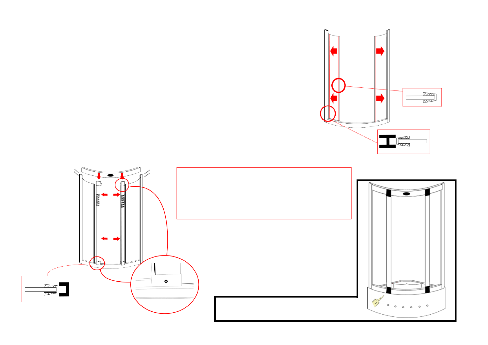
ASSEMBLY AND SIMPLE PLUMBING
THIS PRODUCT BUILD IS RATED SUITABLE FOR DIY PURPOSES PROVIDING THE CUSTOMER IS OF ABOVE AVERAGE SKILLS AND FEELS CONFIDENT IN
THEIR ABILTY. ONLY YOU THE CUSTOMER WILL KNOW THIS SO BEFORE ANY ATTEMPT IS MADE TO ASSEMBLY READ THROUGH THE FOLLOWING
PAGES IN DETAIL THEN DECIDE. IF YOU HAVE ANY DOUBT USE THE SERVICES OF A PROFESSIONAL. IN PICKING SUCH, ALLOW THEM TO DECIDE IF
THEY ARE CAPABLE OF BUILD BY FIRST SHOWING THESE INSTRUCTIONS TO THEM. ALWAYS GET THREE QUOTES.
REMEMBER THE BEST IS NOT ALWAYS THE CHEAPEST!
REMEMBER PLUMBERS PLUMB! 90% OF THIS JOB IS NOT PLUMBING!
DUE TO THE NATURE OF THIS PRODUCT WE HIGHLY ADVISE THE PURCHASE AND FITTING OF A WATER SOFTENER
ELECTRICAL CONNECTION TO HOUSE MAINS
WHEN YOUR ITEM IS ASSEMBLED ALWAYS USE THE SERVICES OF A FULLY QUALIFIED ELECTRICAL COMPANY TO COMPLETE CONNECTION FROM
SHOWER TO HOUSE SUPPLY. LAWS DEMAND IN MANY CASES YOU DO THIS AND YOUR WARRANTY IS VOID REGARDS ELECTRICAL ITEMS IF THIS IS NOT
UNDERTAKEN.
YOURS AND OTHERS SAFETY IS PARAMOUNT. NEVER ATTEMPT THIS YOURSELF.
REMEMBER:
These showers are designed to be free standing and movable from their location should you have need to replace anything. ALWAYS USE Flexible braided water inlet
pipes at least a metre long (not central heating plastic type! )
from house supply to the shower and again flexible waste pipe to join to your house waste. NEVER fix with rigid pipes, never fix the unit to the wall.
DURING BUILD, LIKE ALL SHOWERS CORRECT SEALING IS IMPERATIVE.
ATTENTION
ALWAYS FIT EASY TO GET TO TAPS ON BOTH HOT AND COLD WATER SUPPLY. AS A DISHWASHER OR WASHING MACHINE, THIS
PRODUCT MUST BE ISOLATED WHEN NOT IN USE. FLEXI SUPPLY HOSES (SUPPLIED) COUPLE HERE AS ORIGIN OF SUPPLY
www.insigniarange.com Last Modied: 07/10/2015
05
YOU WILL NEED
TOTAL ELECTRICAL REQUIREMENTS
Voltage Rating 220 -240AC
Frequency Rating 50HZ
Power Rating 3.0KW
Other than steam generator
Internal Circuit Voltage is 12V
Internal Current Rating 0.17A
Your electrical contractor should understand ALL legal requirements of connection before undertaking any work or installation.
UNDER NO CIRCUMSTANCES UNDERTAKE THIS YOURSELF!!!
Note for electrician. This product comes with 13 amp plug(s) fitted with an RCD unit. We leave it this way for you to connect this your own way due to continued additions
to current regulations. As at October 2010 we offered two methods.
1) Connect within current laws and IP directives using plug and RCD provided with steam version or supply one for non steam version
2) (Preferred) Wire into isolated fused feed connecting directly to the house consumer/service box. Remove the fitted plug and ensure the Consumer unit has capabilities to
replace RCD feature if RCD is removed.
Always use protection against electrical surge. Your shower should be treated the same as a home computer. A surge protector should eradicate the possibility of either
the transformer or computer control being burnt out. Please note earth is required and found on chassis of shower tray. A further earth is required from Steam Generator
unit. Each earth must ground through power supply line.
Requirements
Scissors Stanley Blade Silicone Gun Spirit Level Tape Measure Philips Screwdriver Electric Drill
www.insigniarange.com Last Modied: 07/10/2015
06
Whilst the next steps show you how to assemble your shower we want to make sure you have a correct build to ensure you get a trouble free shower. Therefore our advice
is to follow the instructions and perform a dry run to ensure you are confident with the build and you understand fully how the unit is assembled. When we use the word
“DRY RUN” this means you do not silicone anything, just simply construct the shower, align, drill and screw everything together. Once you are happy with the build take the
unit apart and carry out the final fix.
What’s In The Boxes?
Tray Box
1x Tray
1x Roof
2x Curved Rails
Internal Accessories, Screw Pack & 2 x extension cables
Glass Room
2x Door seals
2x Glass doors
2x fixed glass
2 x Magnetic Seals
Column
1x Complete column with control panel
2 x Front columns with pre-fitted LEDs
2 x Aluminium Uprights
Backwalls
1x Left Panel Backwall
1x Right Panel Backwall
www.insigniarange.com Last Modied: 07/10/2015
07
Insignia Screw Pack
VERY IMPORTANT
Have you got everything? If not please contact the Insignia Support Line on 01908 226545. Remember NEVER book your tradesman until everything has arrived, been
checked and is present. No replacement/missing parts can be obtained free of charge during or after the build. Any claims can only be within the timescale permitted (48
hours after delivery) and always BEFORE build.
Product Code Descripon Quanty
SP097 Door Handles 2
SP008 Door Wheels 8
ST20 20mm Screws 20
ST35 35mm Screws 10
ST14 14mm Screws 6
ST25 25mm Screws 10
SW9 Small Washers 20
DB6 Drill Piece 1
ST55 55mm Screws 9
Note: In some cases you may have more screws than needed, this is done so you have spares!
www.insigniarange.com Last Modied: 07/10/2015
08
Pressure Requirements from your house supply
We recommend a bar pressure between 2.5 and 3.4 BAR. If you have a combi boiler system no problem should be experienced. If you have a gravity feed older type
installation (hot water tank type usually less than 1 bar) you will almost certainly need a pump. We cannot advise on which type of pump is used, location or design because
all house plumbing layouts vary. This is a job for your installer/plumber. The end delivery however must fall within the scope above.
Debit Requirements
You will need the debit capabilities of at least 10 litres per minute. Again an average combi boiler will supply this but please check if you have a gravity feed system.
Important Note Do not exceed 3.4 BAR pressure under any circumstances. Warranty is void if so as damage will occur. If you have a combi supply, please use a pressure
reducing valve if required to lower the BAR pressure to the shower.
Please Remember that this product is free standing and is designed to be pulled away from the wall. The water supply and waste require flexible pipes. If you purchased the
fitting kit with this shower you will have the required fittings. The water supply pipes need to be at least 1 metre in length and must be that of a flexi braided type..
DO NOT OVERTIGHTEN IT CAN CAUSE THE CONNECTION TO POP AFTER A FEW WEEKS OF USE
Please note if a shower pump is used via gravity system we recommend a separate cold feed bypassing pump direct to generator to avoid damage to the
generator.
Further to this as you would with a washing machine or dishwasher, it is highly recommended that accessible water valve taps are installed to turn off the shower when not
In use. This will avoid any possible flooding due to a burst pipe or connection failure in the future.
www.insigniarange.com Last Modied: 07/10/2015
09
TO START
Make sure you have a clear space, remember when finished and in place you need access to check your build and
able to pull the shower out for servicing or should you have the need to replace anything!
Take the shower tray and remove all the protective wrapping and fit the waste. If you purchased the fitting kit it is
possible this may have already been fitted in the tray hole yet please note this is only for transportation reasons
therefore you will still need to ensure the correct sealing and alignment is carried out. In the side of the waste
supplied in the optional fitting kit you will notice a spigot not seen on an ordinary waste. In most cases this is blanked
yet should you have a steam version you need to gently drill this out as this item is for the steam generator drainage
and will be connected in the instructions later.
Now please level the tray by firstly placing the tray in its final location and then using a spirit level, adjust the tray feet
accordingly. Once you are happy with the levelling of the tray, you can pull it out to begin the main construction.
Step 1
Attach the uprights to the bottom curved rail using the ST55 screws
(Thinner rail without Insignia logo on)
www.insigniarange.com Last Modied: 07/10/2015
10
Step 2
Push the “U Shape” glass seal onto each side of the glass panels prior to insertion
into the frames.
The next step is to attach both front fixed glass panels. In order to do this take the
glass panel and offer it up to the upright as shown by the arrows.
Step 3
Attach both front uprights and the top rail. In order to do this insert the front uprights
over the glass seal as push on tightly as directed by the arrows in the image. The
columns are handed and can only fit one way.
Now place your completed front frame on the front of
the shower tray as per the image on the right
IMPORTANT! When fitting the top rail ensure the wires
from the column lights are held against the back of the
grey plastic clips poking out of the top. The rail is
designed to sandwich the wires between the front of the
rail and the back of the grey clips.
Now attach the top rail (wide rail with logo) and then screw
into place using the ST55 screws
Once the top rail is in place, secure the front uprights to the
top and bottom rails (from inside the cabin)
using ST14 screws
Once you are happy with the alignment, run a bead of
silicone along the bottom of the frame
www.insigniarange.com Last Modied: 07/10/2015
11
Step 4
Run a bead of silicone along the bottom of the back panels and lock the back glass
panel to the completed front frame in the position shown in the image marked “1”
Once you have met the back panel inside the front upright as per the close up image
walk the panel around to the position shown in the image marked “2”
Now repeat for the other side
12
1
Step 5
Now you have locked the two back panels in position, align the back
panels to the central column. Once you are happy with the alignment,
apply silicone to the bottom of the centre column and screw all parts to-
gether using the ST20 screws and SW9 Washers as per the image.
Note: you may have a clear seal which sandwiches
between the column and backwall, ensure this is completely flat before
screwing the panels together.
(please note, if your column has a rubber seal at the bottom, take
the rubber off and apply silicone inside the rubber and replace)
www.insigniarange.com Last Modied: 07/10/2015
12
Step 6
Align the roof with your shower walls and using the ST25 screws and SW9 Washers
fix the back walls to the roof by screwing upwards from the rear of the shower.
NOTE: You will notice you have 2 holes pre-cut in the front curve of the underside of
the roof. You need to pass the wires through for the front column lights here ready to
connect later.
if a small gap exists silicone seal later
Step 7
Fit the adjustable wheels to the top and bottom of the glass doors and ensure the wheels
are at their lowest position and hang on the inner curved rails with the wheels facing the
outside of the glass.
Once all wheels are fitted and on the rails you can adjust the wheels by turning the plastic
bolt clockwise in which in turn will pull the wheels towards the track ensuring a secure a
tight fit.
Now grease the track to ensure a smooth and long lasting operation
(not supplied)
www.insigniarange.com Last Modied: 07/10/2015
13
Shelf
Fix the chrome floating shelf brackets to your glass back panel
by using the provided screws. Now attach the chrome tubed
bars to your glass shelf as illustrated in the image. Next slide
the shelf into your shelf brackets and secure by tightening the
grub screw situated on the bottom of the bracket.
Accessory Installation
Please Note
Ensure all grey backing film on the rear of the glass panels are pierced through the existing glass holes
with a knife to provide an efficient smooth fitting and location of the accessories. We recommend using
a screwdriver on the smaller holes.
Back Backrest
The back rest is secured in to position by pushing it on to
the 4 retaining knobs.
www.insigniarange.com Last Modied: 07/10/2015
14
Hand Shower
Attach the chrome riser bar to the glass wall ensuring the water inlet is inserted
through the lower large hole and hand tightened from the rear side.
Now tighten the chrome shower holder ensuring that this will take the hand shower
itself without falling (please note over tightening will prevent the holder from sliding up
and down)
Thermostatic Probe
Locate the probe which is wired in to the main electric box and insert the probe into
the hole situated below the control panel roughly 6mm into the cabin. Next run clear
silicone around the rear side of the probe to keep it securely in position.
Ozone (o3)
Unscrew the chrome pepper pot end and drop the white box upside down into the
rear hole as shown in the image. Now from the inside of the shower re-attach the
chrome pepper pot end and tighten.
Monsoon Head
Attach the grey hose from your valve to the inner black tube using PTFE tape
(please note this only needs to be hand tight. Over tightening will snap/damage the
inner black tube)
Handle
Ensuring that the inner thread is protruding out from the handle far enough, place
the handle on the outside of the door and secure by tightening the inner chrome
knob to the protruding inner thread.
Steam Pod
Insert the pod from the inside of the shower and attach large white nut from the rear.
www.insigniarange.com Last Modied: 07/10/2015
15
Door Seals
Magnetic Seal: Push the magnetic door seal on the handle side of the glass door ensuring this is
tightly fitted.
Rear Door Seal: Place the rear door seal on the opposite side to the magnetic strip ensuring the
flap is facing the fixed glass panel
Hot Water InletCold Water Inlet
Open Outlet For
Steam Generator
Shower Valve
Connect the corresponding hoses to the rear of the valve as shown.
Device output may differ from the image. Please refer to your outer chrome faceplate in-
side your Insignia shower as a reference point.
IF YOUR DIAL DOES NOT CORROSPOND TO THE APPROPRIATE DEVICE:
Turn on your water to the shower and note which output the water exits from then turn off
the water and swap over the relevant hose.
Alternatively remove the outer chrome knob by removing the chrome cap and loosening
the grub screw (please ensure not to unscrew fully as this will drop within the chrome
knob) this is found on the opposite side to the chrome pillar. Once you have succeeded in
loosening this you can now slide your faceplate to correspond to the device.
Body JetsHand Shower
Monsoon Shower
www.insigniarange.com Last Modied: 07/10/2015
16
Connecting the Front Column lights
1. Locate the grey extension cable which has a white
connection block on one end and a spit male/
female lead the other.
2. Locate the wires from the front columns (left/right)
and screw in the 4 wires matching each colour. E.g
2 x reds together and 2 x black together and tighten
securely in to the connection block.
3. Locate the other end of the wire with the 2 connect-
ors on (1 x male and 1 x female) and plug the
female end up to the corresponding symbol found
on the wire coming from the electric box
4. With the last remaining connector ( 1 x male) con-
nect this up to the corresponding symbol which is
found on the back lights of the centre column (12
leds above the control panel).
5. Wrap some electrical tape around the connector
block on the roof to protect the circuit.
www.insigniarange.com Last Modied: 07/10/2015
17
Connecting the Tray lights
1. Locate the black supplied extension lead and con-
nect the end with the single connection to the light
on the roof of the shower as shown in the image.
2. Locate the 2 other connections on the at the oppo-
site end and connect one end to the tray lights
3. With the last remaining connector, connect this up
to the lead supplied from the electric box represent-
ing a light bulb symbol.
www.insigniarange.com Last Modied: 07/10/2015
18
Electric Box/Steam Generator Connections
Fan
Speaker
Ozone
Light
Light 2
Thermostac Probe
RJ11 Phone Connecon
Radio Aerial AUX Audio In Connecon
Phone Connecon
This feature, if ed has now been disabled. Please do
not connect as it will not work.
www.insigniarange.com Last Modied: 07/10/2015
19
The steam generator has 3 connections.
Steam Outlet: Connect the white insulated hose to the white steam pod within your shower. Make sure these are fitted in the correct position as they are
only attached for transportation reasons only.
Water Inlet: Connect a braided hose from the shower valve’s centre feed to this opening.
Drain: Connect the grey rubber hose from the steam generators drain opening to the nozzle on the shower waste (as shown in the below image)
Steam Generator Connections
www.insigniarange.com Last Modied: 07/10/2015
20
Silicone Seal where shown in red on the inside of the shower
TESTING FOR WATER LEAKS
LEAVING SHOWER 24 HOURS AFTER BUILD ALLOWING SEALENT TO CURE
With all connections tight, the waste and hoses checked, jets fully sealed, your shower still around 18 inches
from its designated final resting point and the silicone fully cured (hence leaving for 24 hours minimum)
Switch on the overhead shower NOT the massage jets, remember these will fire water out at you and are
not suitable for checking leaks as they would normally only operate when a person is in front of them. Just
use COLD water setting as hot will make cabin misty and condensate thus the inspection becomes very
difficult. Now on the OUTSIDE of the shower inspect each joint, factory seal, hose, clip and jet by walking
from one side and going around to the back and then to the other side finishing at the front. If you have a
small leak (normally caused through insufficient sealer or air bubble on assembly, dry the area thoroughly
and reseal on the OUTSIDE. Please remember where you see the water this may not be exactly where the
leak is as it could have run around to a low point. Never seal your inner fittings (accessories) inside unless
you feel it necessary and make sure it is thin and neat, remember you will see this for the life of the shower!
Again leave to cure and check. If all good now check shower functions i.e. jets for back massage,
foot massage, (if you have one) and finally hand shower, check your joints to these functions at the rear
again. Never use the shower until all checks have been made and the installer is 100% happy in the
knowledge no leaks are present.
All good?
Now push your shower FROM THE BASE NEVER GLASS OR FRAME into its final resting position.
Now you can shower in the knowledge that you have no leaks a job done well and long product life.
Happy showering!

Other Insignia Bathroom Fixture manuals

Insignia 1800 Series User manual

Insignia

Insignia 1800 Series User manual

Insignia Premium Series User manual

Insignia

Insignia Premium Series User manual

Insignia MY810L User manual

Insignia

Insignia MY810L User manual

Insignia INS8059.1L User manual

Insignia

Insignia INS8059.1L User manual

Insignia 900 User manual

Insignia

Insignia 900 User manual

Insignia Premium Series User manual

Insignia

Insignia Premium Series User manual

Insignia Platinum Series User manual

Insignia

Insignia Platinum Series User manual

Insignia MX Series User manual

Insignia

Insignia MX Series User manual

Insignia ECO Series User manual

Insignia

Insignia ECO Series User manual

Insignia Premium Series User manual

Insignia

Insignia Premium Series User manual

Insignia INS8719 User manual

Insignia

Insignia INS8719 User manual

Insignia GT9014 User manual

Insignia

Insignia GT9014 User manual

Insignia KSY1450 Series User manual

Insignia

Insignia KSY1450 Series User manual

Insignia ES001 User manual

Insignia

Insignia ES001 User manual

Insignia ES009 User manual

Insignia

Insignia ES009 User manual

Insignia INS9012 User manual

Insignia

Insignia INS9012 User manual

Insignia Monochrome Series User manual

Insignia

Insignia Monochrome Series User manual

Insignia Diamond Series User manual

Insignia

Insignia Diamond Series User manual

Insignia 1500 Series User manual

Insignia

Insignia 1500 Series User manual

Insignia Diamond Series User manual

Insignia

Insignia Diamond Series User manual

Insignia MC90CQ User manual

Insignia

Insignia MC90CQ User manual

Insignia Platinum Series User manual

Insignia

Insignia Platinum Series User manual

Insignia GT6000 User manual

Insignia

Insignia GT6000 User manual

Insignia MC115RT User manual

Insignia

Insignia MC115RT User manual

Popular Bathroom Fixture manuals by other brands

Grohe Atrio 20 138 quick start guide

Grohe

Grohe Atrio 20 138 quick start guide

Foremost TIDES NEO-ANGLE installation manual

Foremost

Foremost TIDES NEO-ANGLE installation manual

Kaldewei Centro Duo 2 01-135 installation guide

Kaldewei

Kaldewei Centro Duo 2 01-135 installation guide

American Standard RU101SS installation instructions

American Standard

American Standard RU101SS installation instructions

MERLYN Arysto GHH900HL installation guide

MERLYN

MERLYN Arysto GHH900HL installation guide

EverShower EverShowerV2 Operation manual

EverShower

EverShower EverShowerV2 Operation manual

Excellent RIKO manual

Excellent

Excellent RIKO manual

Mirabelle St. Martin MIRSM4RTGCP quick start guide

Mirabelle

Mirabelle St. Martin MIRSM4RTGCP quick start guide

Sanipex BAGNODESIGN BDP-K9560-ESG3 Instruction guide

Sanipex

Sanipex BAGNODESIGN BDP-K9560-ESG3 Instruction guide

Dolphin Blue DB3100 Installation and maintenance guide

Dolphin

Dolphin Blue DB3100 Installation and maintenance guide

Woodstock WDS1245CD Assembly instructions

Woodstock

Woodstock WDS1245CD Assembly instructions

Hans Grohe Croma 04536 0 Series Installation/User Instructions/Warranty

Hans Grohe

Hans Grohe Croma 04536 0 Series Installation/User Instructions/Warranty

DEVA DLT TSM106 Installation and Maintenance

DEVA

DEVA DLT TSM106 Installation and Maintenance

KEUCO Edition 11 51151 010002 Mounting instruction

KEUCO

KEUCO Edition 11 51151 010002 Mounting instruction

RADSON Bayo Installation & maintenance

RADSON

RADSON Bayo Installation & maintenance

Spectrum Brands Pfister Northcott 016-MG0 Quick installation guide

Spectrum Brands

Spectrum Brands Pfister Northcott 016-MG0 Quick installation guide

Sanela SLSN 19 Mounting instructions

Sanela

Sanela SLSN 19 Mounting instructions

ERLIT ER 10109V user manual

ERLIT

ERLIT ER 10109V user manual

manuals.online logo
manuals.online logoBrands
  • About & Mission
  • Contact us
  • Privacy Policy
  • Terms and Conditions

Copyright 2025 Manuals.Online. All Rights Reserved.