IPC GC 1/35 OIL User manual

Kit Filtrante per versione OIL
Filtering Kit for OIL version
Istruzioni originali
Original instructions

KIT FILTRANTE OIL
2

INDICE
Simbologia......................................................................................................................................... 5
Introduzione....................................................................................................................................... 5
Prescrizioni di sicurezza.................................................................................................................... 6
Componenti principali........................................................................................................................ 7
Uso dell’aspiratore............................................................................................................................. 8
Prima di mettere in moto l’apparecchio ......................................................................................... 8
Assieme......................................................................................................................................... 9
Collegamento del tubo di aspirazione.......................................................................................... 10
Svuotamento del contenitore........................................................................................................11
Manutenzione.................................................................................................................................. 12
Sostituzione della cartuccia ltro. ................................................................................................ 12
Operazioni consigliate dopo ogni 100/200 ore di funzionamento................................................ 12
Operazioni consigliate prima di ogni avviamento giornaliero....................................................... 13
Verica del tubo di aspirazione.................................................................................................... 13
Verica delle tenute ..................................................................................................................... 14
Verica del galleggiante............................................................................................................... 15
INDEX
Symbols............................................................................................................................................. 5
Introduction........................................................................................................................................ 5
Safety conditions ............................................................................................................................... 6
Main Components ............................................................................................................................. 7
Vacuum cleaner use.......................................................................................................................... 8
Before starting the module............................................................................................................. 8
Assembly ....................................................................................................................................... 9
Connection of the suction hose ................................................................................................... 10
Emptying the tank.........................................................................................................................11
Maintenance.................................................................................................................................... 12
Replacing of the lter cartridge.................................................................................................... 12
Suggested operations after 100/200 hours of work..................................................................... 12
Suggested operations before any daily start ............................................................................... 13
Suction hose control .................................................................................................................... 13
Seals control................................................................................................................................ 14
Floater control.............................................................................................................................. 15
KIT FILTRANTE OIL
3

KIT FILTRANTE OIL
4

SIMBOLOGIA
Manuale da conservare per futuri riferimenti.
ATTENZIONE: leggere il manuale di istruzioni
prima di usare l’apparecchio.
QUESTO DOCUMENTO È DA CONSIDERARSI
ALLEGATO AL MANUALE DI ISTRUZIONI
DELLA MACCHINA COMPLETA.
Questa simbologia verrà utilizzata per ricordare
all’operatore di prestare la massima attenzione
su operazioni che possono provocare lesioni,
no alla morte, dell’operatore stesso oppure
a persone o animali presenti nelle vicinanze.
Inoltre le operazioni richiamate da questa
simbologia potrebbero causare danneggiamenti
anche irreparabili all’aspiratore.
INTRODUZIONE
Il sistema è stato progettato per permettere di
aspirare simultaneamente sia liquidi sia detriti
solidi (tipicamente olio ed emulsioni contenenti
trucioli e sfridi metallici derivanti dalle lavorazioni
meccaniche) impedendo che questi raggiungano
il blocco motore.
SYMBOLS
It is recommended to keep this manual for future
references.
WARNING: please read carefully the instruction
manual before using.
THIS DOCUMENT IS AN ATTACHMENT OF
VACUUM CLEANER’S INSTRUCTION MANUAL.
These symbols will be used to remind the
operator to pay attention to operations that may
cause lesions, including death, to the operator or
to other people or animals nearby. Furthermore,
the operations indicated by these symbols may
cause damages, even irreparable ones, to the
suction device.
INTRODUCTION
The system has been designed to pick up liquids
and solid debris simultaneously (typically oil and
emulsions containing shavings and metal scraps
deriving from mechanical processing) preventing
them from reaching the motor head.
KIT FILTRANTE OIL
5

PRESCRIZIONI DI SICUREZZA
-Non aprire il serbatoio con l’aspiratore in
funzione.
-Prima di essere utilizzato l’apparecchio deve
essere montato correttamente in ogni sua parte.
Vericare che gli elementi ltranti previsti siano
correttamente montati ed efcienti.
-ATTENZIONE: in caso di fuga di schiuma o
liquido spegnere il motore.
-Non aspirare acqua da recipienti, lavandini,
vasche, ecc.
-Non aspirare detergenti aggressivi poiché
potrebbero danneggiare l’apparecchio
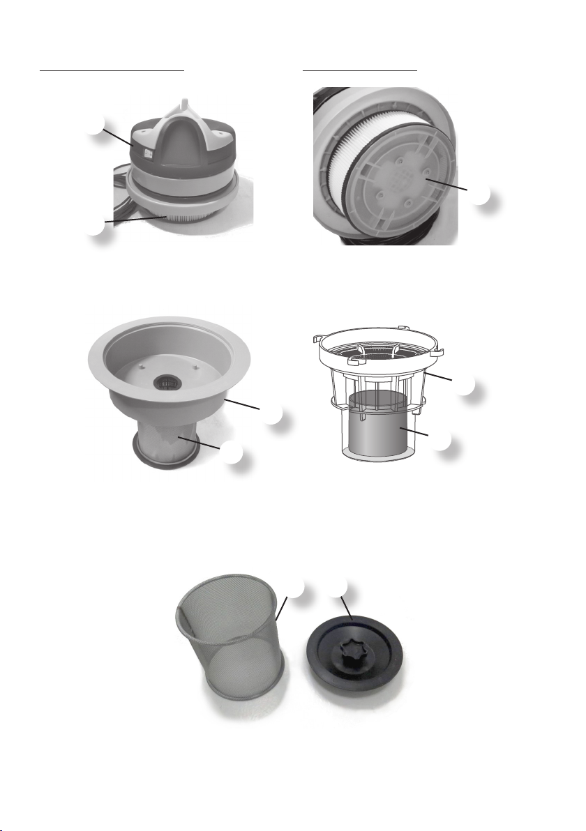
-ATTENZIONE: Il galleggiante ha la funzione di
arrestare l’aspirazione quando il fusto è pieno
di liquido o in caso di ribaltamento; procedere
regolarmente alla sua pulizia controllando anche
che non presenti danneggiamenti e sostituirlo
se necessario.
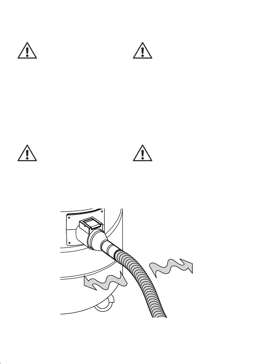
-ATTENZIONE: Quando il liquido aspirato
raggiunge il corpo antischiuma, il galleggiante
interviene per impedire che i liquidi raggiungano
il motore. In questo caso la macchina perde il
suo potere aspirante mentre il motore continua a
funzionare. Spegnere la macchina o procedere
allo svuotamento del fusto.
-ATTENZIONE: è vietata qualsiasi modica
all’apparecchio.Lamanomissionepuòprovocare
incendi, danni anche mortali all’utilizzatore oltre
al decadimento della garanzia.
-Manutenzioni e riparazioni devono essere
effettuate sempre da personale specializzato;
sostituire solo con ricambi originali.
-Il fabbricante declina ogni responsabilità per
danni causati a persone o cose in seguito
al mancato rispetto di queste istruzioni o se
l’apparecchio viene usato in modo irragionevole.
SAFETY CONDITIONS
-Do not open the tank while the vacuum cleaner
is working.
-Every part of the appliance must be correctly
assembled before using it. Verify, furthermore,
that the ltering elements have been correctly
and efciently assembled.
-WARNING: in case of foam or liquid leakage
switch off immediately.
-Do not vacuum water from containers, sinks,
basins, etc.
-Do not vacuum corrosive soaps because they
could damage the machine.
-WARNING: The oater has the function to stop
the vacuuming when the tank is full of uids
or in case of overturning; carry out routine
cleaning checking that it has no damage and
change it if it’s necessary.
-WARNING: When the sucked up liquid level
reaches the oater cage the oater intervene,
to avoid that the liquid reach the motor. In this
case the appliance lose its suction power while
the motor keeps working. Immediately turn off
the machine and empty the tank.
-WARNING: It is forbidden to do any kind of
change on the appliance. Tampering could
cause res and damages even lethal to the
user and the forfeiture of the guarantee.
-Specialized personnel must always carry out
maintenance and repairs; any damaged part
must be replaced with original spare parts.
-The manufacturer declines any responsibility
for damages caused to people or things due to
non-compliance of these instructions or if the
appliance is not properly used.
KIT FILTRANTE OIL
6

8
5
1
2
3
5
4
6
7
COMPONENTI PRINCIPALI MAIN COMPONENTS
1 - Testata motore
2 - Cartuccia ltro
3 - Disco bloccaltro (per cartuccia ltro)
4 - Supporto ciclone
5 - Filtro rete che contiene corpo antischiuma
6 - Corpo antischiuma
7 - Galleggiante
5 - Filtro rete
8 - Disco bloccaltro (per ltro rete)
1 - Motor head
2 - Filtering cartridge
3 - Locking lter plate (for cartridge lter)
4 - Cyclone module
5 - Filtering grid that include oater cage
6 - Floater cage
7 - Floater
5 - Filtering grid
8 - Locking lter plate (for ltering grid)
KIT FILTRANTE OIL
7

10
9
DATI, DESCRIZIONI E ILLUSTRAZIONI SONO
FORNITI A TITOLO INDICATIVO. LA DITTA SI
RISERVA DI MODIFICARLI SENZA PREAVVISO.
ATTENZIONE: LE MACCHINE IN QUESTA
CONFIGURAZIONE MONTANO LA CARTUCCIA
FILTRO SOTTO LA TESTATA E IL CORPO
ANTISCHIUMA SOTTO IL SUPPORTO CICLONE.
DATA, DESCRIPTIONS AND PICTURES ARE
PROVIDED ONLY AS A GUIDE. WE RESERVE
THE RIGHT TO CHANGE THESE DATA
WITHOUT NOTICE
WARNING: APPLIANCES IN THIS SETTING
HAVE THE CARTRIDGE FILTER UNDER THE
HEAD, AND THE FLOATER CAGE UNDER THE
CYCLONE MODULE
USO DELL’ASPIRATORE
Prima di mettere in moto l’apparecchio
-Vericare che tutte le parti e gli elementi ltranti
siano presenti e montati correttamente.
-Controllare che il galleggiante -7- sia integro e
libero di muoversi nella sua sede.
VACUUM CLEANER USE
Before starting the module
-Check that all the parts and the ltering
elements are in place and correctly assembled.
-Check that the oater -7- is intact and free to
move inside the oater cage -6-.
9 - Bocchettone
10 - Fusto
9 - Inlet
10 - Tank
KIT FILTRANTE OIL
8

1
2
4
7
6
5
8
10
Assieme
1 Testata
2 Cartuccia ltro
4 Supporto ciclone
7 Galleggiante
6 Corpo antischiuma
5 Filtro rete
8 Disco bloccaltro (per ltro rete)
10 Fusto
Assembly
1 Motor head
2 Filter cartridge
4 Cyclone module
7 Floater
6 Floater cage
5 Filtering grid
8 Locking lter plate (for ltering grid)
10 Tank
KIT FILTRANTE OIL
9

Collegamento del tubo di aspirazione
Si raccomanda di utilizzare il kit antiolio
(optional) che comprende tubo in
gomma antiolio antistatico e accessori
in acciaio.
Il tubo di aspirazione deve essere sempre tenuto
disteso per favorire la corsa del residuo al suo
interno: ogni rallentamento dovuto a curve o
strozzature provoca il lento intasamento del tubo
stesso.
Se dovesse intasarsi, scuoterlo con movimenti
ondulatori a partire dal bocchettone no
all’estremità per favorire il disintasamento.
ATTENZIONE: usare soltanto gli
accessori originali forniti con
l’apparecchio o quelle specicate nel
manuale di istruzioni.
L’uso di altri accessori può compromettere la
sicurezza.
Connection of the suction hose
WARNING: It is recommended to use
oilproof kit (optional) that includes a
rubber oilproof antistatic hose and
steel accessories.
The exible hose must always be kept unrolled
in order to allow the scrap to easily run inside it
and reach the tank: any slowing due to bends
or narrowing causes the obstruction of the hose
itself.
If it’s blocked, shake it with waving movements.
WARNING: we recommend to use
only accessories provided with the
equipment or those reported in the
handbook of instructions.
Using other accessories may threaten operator
safety.
KIT FILTRANTE OIL
10

Svuotamento del contenitore
Quando il livello del liquido nel fusto raggiunge
il galleggiante -7-, quest’ultimo interviene per
impedire che i liquidi raggiungano la testata
dell’aspiratore. Si ha come risultato una ridotta
capacità aspirante. E’ quindi necessario
procedere allo svuotamento del fusto.
E’ consigliabile svuotare il fusto
periodicamente, prima che il liquido
nel fusto raggiunga il galleggiante.
-Spegnere l’apparecchio;
-Svuotare il fusto;
-Controllare che il ltro rete -5- sia privo di
residui e all’occorrenza rimuoverli;
-Controllare che il galleggiante -7- sia integro e
libero di scorrere nella sua sede, all’interno del
corpo antischiuma -6-;
-Controllare anche che il tubo di aspirazione sia
vuoto nella sua lunghezza.
A questo punto l’operazione è conclusa, è
quindi necessario rimontare correttamente i
componenti (vedi esploso pagina 9).
Emptying the tank
When the oil level inside the tank reaches the
oater -7-, the oater lift, avoiding that the liquid
reaches the motor head. Therefore the suction
power is reduced. It is then necessary emptying
the container.
We suggest you to periodically empty
the tank, before the liquid level reaches
the oater.
-Turn off the appliance;
-Empty the tank;
-Check that the ltering grid -5- is free from
scraps.
-Check that the oater -7- is free of debris that
can block the oater motion to move inside of
the oater cage -6-;
-Check also that the exible hose is unclogged.
Now you can work backwards, taking care
that components are correctly assembled (see
assembly at page 9)
KIT FILTRANTE OIL
11

1
3
MANUTENZIONE
Sostituzione della cartuccia ltro.
-Sbloccare i ganci e sollevare la testata -1-;
-Girare il disco bloccaltro -3- per sbloccarlo e
rimuoverlo dalla cartuccia;
-Rimuovere la cartuccia da sostituire;
-Posizionare la cartuccia nuova in modo tale da
allinearla con le guide della testata;
-Riposizionare il disco bloccaltro.
MAINTENANCE
Replacing of the lter cartridge
-Unlock the hooks and lift the motor head -1-;
-Turn the locking lter plate -3- to unlock it and
remove it from the cartridge;
-Remove the old lter cartridge;
-Place the new lter cartridge and align it with
the guide placed on motor head;
-Ret the locking lter plate.
Operazioni consigliate dopo ogni 100/200 ore
di funzionamento
-Vericare le tenute delle guarnizioni della
testata e del fusto.
-Vericare lo stato di integrità del fusto.
-Vericare lo stato di tutti i ltri (cartuccia,
ltro rete, corpo antischiuma). Non devono
presentare fori o lacerazioni. In tal caso è
necessario sostituirli immediatamente.
-Vericare lo stato di integrità dell’etichetta di
targa che riporta tutti i dati tecnici. In caso fosse
illeggibile si prega di far richiesta al costruttore.
-Vericare lo stato di integrità delle ruote.
Suggested operations after 100/200 hours of
work
-Check the seal of the gaskets of the motor
head and the tank.
-Check the conditions of the tank.
-Check the conditions of all the lters (cartridge,
lter grid, oater cage). They must not have
holes or cuts. In this case you must replace
them.
-Check the conditions of the label reporting all
technical data. If it should it be illegible, please
contact the manufacturer company.
-Check the conditions of the wheels.
KIT FILTRANTE OIL
12

Operazioni consigliate prima di ogni
avviamento giornaliero
-Controllare visivamente l’integrità del cavo di
alimentazione dell’aspiratore.
-Controllare l’integrità e la funzionalità di tutti i
comandi elettrici presenti sull’aspiratore.
-Controllare visivamente l’integrità dell’unità
ltrante.
-Controllare lo stato di riempimento del serbatoio.
-Controllare visivamente l’integrità del tubo di
aspirazione e degli accessori.
-Vericare la tenuta alla chiusura dei ganci della
testata.
-Se l’aspiratore viene spostato, vericare che la
tensione di alimentazione presente nella presa,
corrisponda alla tensione riportata sulla targa
dati tecnici dell’aspiratore.
Verica del tubo di aspirazione
Col passare del tempo ed in condizioni di lavoro
particolarmente gravose, è possibile che il tubo
di aspirazione perda la sua originaria efcienza.
In questo caso avviene una diminuzione della
capacità di aspirazione.
Questo può avvenire per molteplici motivi legati
all’uso, per esempio:
-Schiacciamento con carrelli di trasporto
materiali
-Tipo di materiale aspirato
-Ambienti particolarmente aggressivi
-Sfregamenti continui su superci abrasive o
angoli taglienti
Si consiglia di controllare periodicamente che il
tubo si presenti completamente privo di residui
di aspirazione al suo interno e che non sia
esternamente danneggiato o tagliato.
Suggested operations before any daily start
-Check that the power cord of the vacuum
cleaner is not damaged.
-Check the efciency of all electrical controls
present on the vacuum cleaner.
-Check that the ltering unit is not damaged.
-Check the lling level of the tank.
-Check that the suction hose and other
accessories are not damaged.
-Check the seal of the gasket when you close
the hooks of the motor head.
-If the vacuum cleaner is moved, check that
the line voltage corresponds with the voltage
reported on the label of the vacuum cleaner.
Suction hose control
In time and particular hard conditions of work, it
is possible that the suction hose loses its original
efciency.
This will involve a decrease of the suction power.
This can happen for different reasons linked to
the use, for example:
-Crushing due to forklift trucks
-Nature of material sucked up
-Particularly aggressive environments or soaps
-Continuous rubbing on abrasive surfaces or
sharp corners
We suggest to periodically check that the hose
does not shows any dirt inside it and that it is not
damaged outside.
KIT FILTRANTE OIL
13

15
Verica delle tenute
Col passare del tempo ed in condizioni di lavoro
particolarmente gravose, è possibile che le
guarnizioni di tenuta perdano in parte la loro
funzionalità.
In questo caso avviene una diminuzione della
capacità di aspirazione.
Si consiglia di controllare periodicamente tutti i
ganci e le guarnizioni di:
-Tenuta del fusto;
-Tenuta del bocchettone -9-;
-Tenuta del galleggiante -7- (vedi pagina
seguente), che sia libero di muoversi nella
sua sede e posizionato correttamente, e che
l’alloggiamento sia privo di trucioli;
-Tenuta della guarnizione -15- montata sul
supporto ciclone;
-Tenuta della guarnizione della testata.
Vericare inoltre se il bordo del serbatoio è stato
danneggiato da un uso improprio (es. capovolto e
picchiato per terra).
Seals control
As time went by, in particularly hard conditions of
work, it is possible that sealing gaskets partially
lose their functionality.
This will result in a decreasing suction power.
We suggest to periodically check all the hooks
and the gaskets of:
-Tank sealing;
-Sealing of suction inlet -9-;
-Sealing of oater -7-, it must be free from
scraps or debris and must be free to move;
-Sealing of gasket -15- placed at the center of
cyclone module.
-Sealing of the gasket of the head.
Check also if the border of the tank has been
damaged due to an improper use (ex: turned
upside down and hit the ground).
KIT FILTRANTE OIL
14

B
5
6
7
Verica del galleggiante
-Sbloccare i ganci ed estrarre la testata -1-;
-Svitare il pomolo del disco bloccaltro -B- e
slare il ltro rete -5-;
-Ruotare in senso antiorario il corpo antischiuma
-6- per sganciarlo dal supporto ciclone -4-;
-Estrarre il galleggiante -7- e vericare che sia
integro e libero di scorrere nella sua sede.
ATTENZIONE: Se l’aspiratore in funzione
non aspira o aspira poco, potrebbe essere che
il galleggiante è intervenuto per impedire che il
livello del liquido raggiunga la testata motore.
In questo caso spegnere l’aspiratore e
controllare il livello nel fusto.
Se il livello del liquido è basso, controllare che
la cartuccia ltro non sia intasata e che il tubo di
aspirazione sia libero da eventuali blocchi.
WARNING: If the suction power is reduced, it
could be that the oater is blocking the airow to
avoid that the liquid reaches the motor head.
Turn off the vacuum cleaner and check the liquid
level inside the tank.
If the liquid level is low, check if the ltering
cartridge is not clogged and the suction hose is
free from scraps or debris.
Floater control
-Unlock the hooks and lift the head -1-;
-Unfasten the plate knob -B- and remove the
lter grid -5-;
-Turn the oater cage -6- counterclockwise to
unhook it from the cyclone module -4-;
-Remove the oater -7- and verify that is whole
and free to move inside of the oater cage.
KIT FILTRANTE OIL
15

IP Cleaning S.r.l.
Internet address: http://www.ipcworldwide.com
Sede Legale/Amministrativa - Registered Ofce/Administration
V.le Treviso, 63 - 30026 Summaga di Portogruaro (Venice) Italy
Tel. +39 0421 205511 Fax +39 0421 204227
Sede produttiva - Production premises
Via E.Fermi,2 – 26022 Castelverde (Cremona) Italy
Tel. +39 0372 424611
Fax Export: +39 0372.429398 Italia: +39.0372.429392
DATI, DESCRIZIONI E ILLUSTRAZIONI SONO FORNITI A TITOLO INDICATIVO. LA DITTA SI RISERVA DI MODIFICARLI SENZA PREAVVISO
DATA, DESCRIPTIONS AND PICTURES ARE PROVIDED ONLY AS A GUIDE. WE RESERVE THE RIGHT TO CHANGE THESE DATA WITHOUT NOTICE.
PLDC04341-00
Table of contents
Other IPC Vacuum Cleaner manuals

IPC
IPC PLANET OIL 3-PHASE User manual

IPC
IPC PLANET 60 Operating instructions

IPC
IPC YP 1/5 BACKPACK User manual

IPC
IPC MAXIBAG User manual

IPC
IPC SG-30 P 5510 M User manual

IPC
IPC SP13 M Operation instructions

IPC
IPC GS 3/78 OIL User manual

IPC
IPC PLANET 300 Pneumatic ATEX for Zone 22 Ex User manual

IPC
IPC Planet 50P Operating instructions

IPC
IPC NRG 1/20 CLEAN P User manual