IPC SG-30 P 5510 M User manual

Service Manual
Rev.1.0 February 2015
SG-30 P 5510 M

Pag. 2
SG
-
30
outer layout
Steam ready green lamp
Vacuum plug
Water tank refill cap
Water lack red lamp
Handle
Standard accessories kit
(
steam + vacuum
)
Standard handle (steam + vacuum)
–
length 2,5 m
Steam pressure gauge
Steam flow
adjustment
Electric controls plug
Heating element
2, power switch
Heating element
1, power switch
Main power switch
Not used
Detergent tank refill cap

Pag. 3
SG
-
30
outer layout
& handgrip
Power supply cord
Airflow exhaust silencer
Electric controls plug
Recovery tank hinges
Recovery tank with water for air filtration
Vacuum switch
Chemical injection button
Steam switch
Data plate

Pag. 4
SG
-
30
functioning principle
SG-30 is a steam generator suitable for professional continuous usage and provided with self-refill of
water to the steam boiler, vacuum system to collect the dirt moisture and chemical injection combined
with the steam stream.
Water self
-
refill
scheme

Pag. 5
The heart of SG-30 is the steam boiler that is a stainless steel pressure vessel with heating elements
inside to generate the steam.
The steam generation follows physical rules and particularly the enthalpy rule that puts in direct
relation the steam pressure and the steam temperature.
Any steam generator, to achieve a certain temperature to the steam [°C], has a correspondent
pressure [bar] as below.
SG-30's boiler pressure setting is about 5 - 5,5 bar, accordingly the maximum steam temperature
into the boiler will be 150°C, but since during the normal use, the pressure fluctuates, the average
steam temperature will be about 140°C.
Accordingly with the enthalpy rule, when the steam stream is sprayed in the atmosphere (at the lance
nozzle) the steam that is physically in gas status, condensates and become liquid (water), so at 0 bar
when the steam changes its physical status, its temperature is always of about 97 °C.
If checked with a thermometer the temperature at the nozzle, it will always be lower than 100°C
despite the steam generator boiler temperature be much higher.

Pag. 6
SG-30 inner layout & components
functionality description
Steam flow adjusting valve
Control switches
Vacuum turbine
Steam outlet line
Chemical injection line
Steam electro valve
Water tank with water level sensors (electrodes)
Chemical tank with level sensors (electrode)
Steam boiler with
thermal insulation cover
Water pump to refill the boiler
Chemical pump to ignite the chemical
Vacuum pipe

Pag. 7
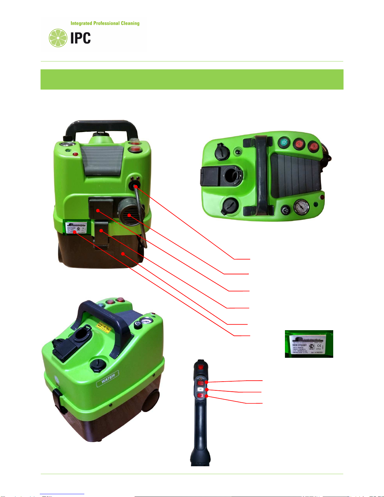
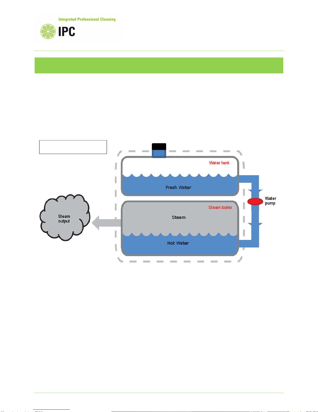
Water tank – the water tank has a capacity of 1,5 liters and is provided with electrodes that thanks to the
water conductivity, detect the water level into the tank.
The electrodes sensor is connected to the electronic board and in case the tank is empty, the water
pump that refills the boiler is deactivated and the red lamp on the machine (water lack) is on.
Water to be used for the steam generator cannot be demineralized water, since the water level detection
is done by electrodes that measure the water own conductivity.
Water pump to refill the boiler – the water pump brings the water from the water tank into the boiler,
this in order to compensate the discharge of steam and keep the boiler at its maximum efficiency of
steam production.
The water pump is powered by the electronic card and is activated when the electrodes sensor inside of
the boiler, detect a low water level.
The water pump functioning is fully automatic.
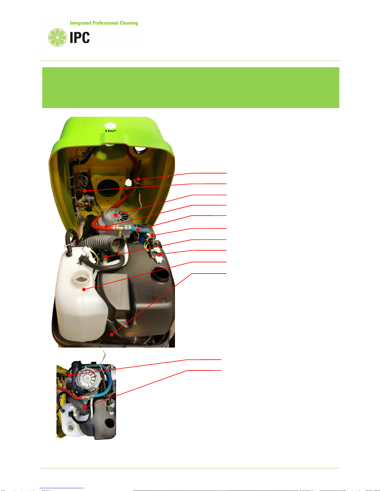
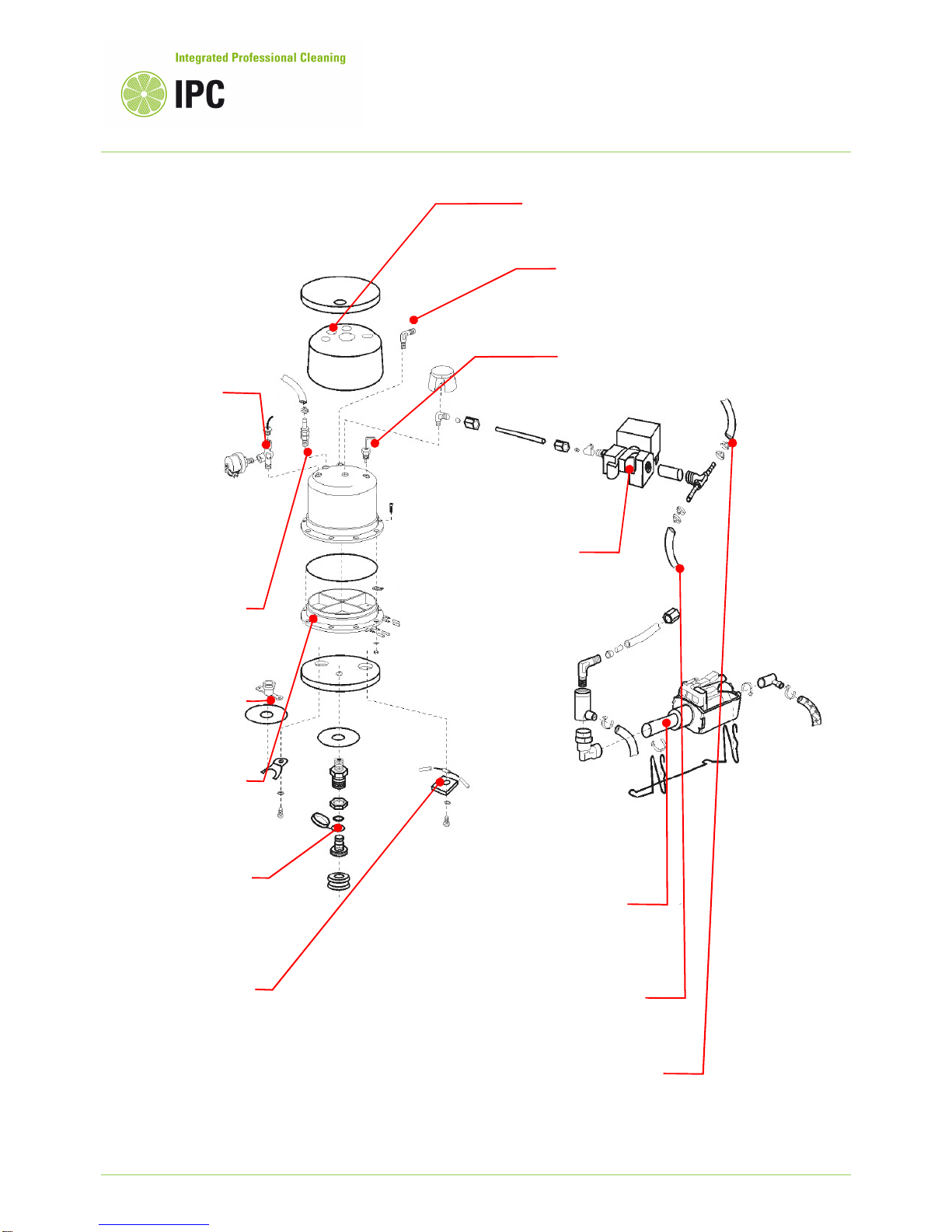
Steam Boiler – The steam boiler has a volume capacity of 1,5 liters and is provided with resistor having
a power of 2kW to generate the steam.
The resistor are two, each is 1Kw and they can be activated separately by the two switches at the top of
the machine.
Here following the boiler breakdown view and the functioning description of the boiler elements.
Electrode for the boiler water level control – This electrode is connected to the electronic board and
detects the water level into the boiler. When low water level is detected, the sensor activates, trough the
electronic card, the water feeding pump that supplies the water into the boiler so restoring the proper
level.
The level detection is possible because the tap water has inside impurities (salts and minerals) so is
weakly conductive, for this machine is not possible to feed the boiler with demineralized water.
Pressure – switch – since the pressure and the temperature of the steam are linked each other and are
proportional, by checking the pressure we can determine the steam temperature.
The pressure switch 5,5 bar, will keep the pressure and the temperature, inside of the boiler, constant,
this by activating or deactivating the heating elements through the electronic board.
Safety valve 7 bar – The safety valve will avoid overpressure conditions into the boiler, keeping safely
the pressure to a maximum of 7 bar in case of boiler malfunctioning.
Safety thermostat – The safety thermostat is a safety component that switches off the boiler in case the
temperature is over than 165°C.
Thermal-Amperometric sensor – This safety element checks the temperature and the current draw to
the heating elements.
This intervenes switching off the heating elements if for some reasons they are powered without having
water into the boiler.
Steam EV – The steam electro-valve controls the delivery of steam at the outlet and is controlled by the
switches placed on the hand grip.

Pag. 8
Thermal insulation to prevent temperature
dissipation and avoid temperature transmission
to the other machine components.
Boiler water
feeding.
Pressure control
switch 5,5 bar that
determines the
pressure and the
temperature
inside of the
boiler. The control
panel pressure
gauge visualize
the pressure read
in this point.
Safety valve 7 bar that
discharges in case of
overpressure of the
boiler, inside of the
detergent tank.
Boiler water feeding
pump, at its outlet
there is an air purge
valve to facilitate
the pump priming.
Detergent injection
line.
Steam and
detergent outlet
line, the outlet goes
to the steam
adjusting tap.
Steam EV to control
the steam delivery
on – off.
Boiler diecast
aluminum bottom that
includes the two
heating elements.
Drain tap for boiler
limestone cleaning.
Safety thermostat to
limit the max
temperature.
Thermal
-
Amperometric sensor
to prevent burning of
the heat elements in
case of working dry.
Electrode to detect the water level inside of
the boiler

Pag. 9
Service Manual
INDEX
Topics
1. The machine doesn’t produce steam Page
1a No electrical connection or differential switch intervenes 11
1b No electrical supply to the heating elements of boiler, or
over-temperature detected by the thermal sensors. 18
1c The feeding water pump not supply water into the boiler
19
1d Electronic card burnt or damaged 21
1e Pressure switch not functioning 23
1f Water level probe not properly detects the boiler water level 23
2. The machine produce steam into the boiler, but is not streamed at the lance. Page
2a Electro-valve clogged or burnt 24
2b Outlet circuit clogged by limestone 24
2c Steam stream adjusting tap clogged by limestone or completely closed 24
2d Hand grip electric controls not work 25
2e Plug that connects hose and machine is not electrically connected 25
2f Electronic card burnt or damaged. 25
2g Main switch not closing 26
3. The steam delivery at the lance is very poor or extremely wet Page
3a Steam circuit clogged by limestone 27
3b Water level sensor not working or boiler fully filled with water 27
3c Electro-valve not opening completely (partially clogged) 28
3d Steam stream adjusting tap in position closed or clogged 28
3e Steam leakages into the machine circuit or in the accessories 28
3f The steam circuit need maintenance and particularly the
limestone cleaning 28
Ip Cleaning S.p.A.
Viale Treviso, 63 – 30026 Summaga di Portogruaro – VENICE – ITALY
Tel. +39 0421 205511 (r.a.) – Fax +39 0421 204227
Internet address: www.ipcportotecnica.com

Pag. 10
4. Poor or missing detergent delivery Page
4a The detergent circuit has not been loaded before starting the boiler 29
4b The detergent tank is empty 30
4c The detergent pump is damaged or clogged or the circuit is damaged
or has leaks. 30
4d Electronic card burnt or damaged. 30
5. Vacuum turbine not working or the suction is poor Page
5a Vacuum motor/turbine burnt or damaged 31
5b Handgrip vacuum control switch not working 31
5c Plug that connects hose and machine is not electrically connected 32
5d Electronic card burnt or damaged. 32
5e Water level sensors that determine the level of water
for dust filtering into the vacuum tank, are intervened 32
5f The vacuum power is adjusted at minimum position 32
6. The steam delivery or the vacuum system are working continuously Page
and cannot stop.
6a Steam electro-valve defective or locked in position open 33
6b Switches placed on the handgrip defective or wires wired into
the hose that are damaged and in short circuit. 33
6c Electronic card burnt or damaged. 33
7. Limestone cleaning procedure Page
34

Pag. 11
1. The machine doesn’t produce steam
1) TROUBLE: Activating the “main power switch” and then one or both the switches “heating
elements”, the pressure into the boiler doesn’t increase, neither after several minutes, since for
this model the “steam ready” requires about 20’ until the heating elements generate the steam.
CAUSES: 1a No electrical connection or differential switch intervenes
1b No electrical supply to the heating elements of boiler, or
over-temperature detected by the thermal sensors.
1c The feeding water pump not supply water into the boiler
1d Electronic card burnt or damaged
1e Pressure switch not functioning
1f Water level probe not properly detects the boiler water level
REMEDIES:
1a Check the power supply voltage using a “multimeter”.
The machine power supply characteristics are indicated on the machine data plate placed on the
rear side of its chassis.
For single-phase, the allowed voltage tolerance is +/- 5%.
Heating element
2, power switch
Heating element
1, power switch
Main power switch
Data plate and machine serial number

Pag. 12
If the voltage is over or lower than the before mentioned tolerance, the machine electric
components may damaged.
Pay maximum attention while checking electric component: danger of electric shocks.
If at the power socket there is a differential switch, be sure that the switch is on and not tripped
out suddenly just after activating the machine power switches.
This machine must be plugged into a socket provided with earth connection, since several
electric elements are in touch with the water, there may be a voltage dispersion that causes that
the differential switch trips out or may be a differential switch too much sensitive.
We recommend a differential switch having a sensitivity of 30 mA at least.
If the power cord or the power plug is damaged, is necessary its replacement with a new power
cord.
If the control panel switches are defective, so apparently are closed, but electrical circuit is not
powered; in this case is necessary to open the machine and check the switches using a
multimeter.
If switches are damaged, replace them with new switches.
If the thermal – amperometric fuse is intervened few times, then may lose its capacity to self-
reset and so keeps open the power supply circuit.
In this case is necessary to open the machine and check the fuse using a multimeter; the fuse is
placed under the boiler.
To open the machine and check the before mentioned points, proceed as following described:
Unscrew and remove the circular ring that
locks the vacuum socket Slide out the vacuum socket and rotate it
clockwise in order to disconnect it from the
vacuum hose

Pag. 13
Vacuum socket removed and disconnected With the help of a pin or a screwdriver, push
into the machine, the central pin of the
plastic rivets that secure the two plastic
cover shells.
Detail of the plastic rivet without the central
pin Pull to slide out the remaining part of the
rivet that now is free to slide
In case of difficulties, pull out the rivet using
a pincer or in the worst case you can cut it.
The spare part rivets are MPVR40202
Remove the water tank cap and the bracelet
that hold the cap to the tank

Pag. 14
Remove the chemical tank cap and the
bracelet that hold the cap to the tank
Press the tanks down and pull up at the same time
the cover until the cover shells are separated

Pag. 15
Levering with a screwdriver in order to remove the pressure gauge from the cover
In order to facilitate the reassembling, secure
with a band the capillary pipe of the pressure
gauge
Disconnect the capillary pipe from the pressure
gauge
Now the top shell can be completely removed

Pag. 16
At this stage, in order to check the thermal – amperometric fuse, is necessary to disconnect and
remove completely the boiler from its frame; proceed as following described:
Check the main switch with a
multimiter.
The wires light blue color are connecter to the
fuse placed under the boiler
Remove the plastic
cap at the boiler top
Unscrew the outlet fitting and disconnect the pipe Unscrew the water inlet fitting and disconnect the
pipe

Pag. 17
If the boiler is cold, but the thermal amperometric sensor is open (off), is necessary to replace it with a
new sensor.
Unscrew the stainless steel plate that secures the sensor and replace; it in this area the temperature is
quite high, the sensor must be settled to the wiring and then protected by the silicon pipe insulators.
Disconnect the wire from the water
level sensor
Boiler disconnected Unscrew the drain cup at the
boiler bottom
Unscrew the nut that secure the
boiler to the frame Lift up the boiler to check
the fuse Check the fuse using a
multimeter

Pag. 18
1b Pay maximum attention: danger of electric shocks.
Disconnect the machine from the power supply before opening the shells, hence:
Check, using a multimeter, the conductivity of the "heating elements" switches that are the two
switches placed to the control panel that have the red button.
Check the continuity of the safety thermostat that is place as in the following picture.
The safety thermostat opens if the temperature of boiler is over 165°C and is self-resetting, but if
it intervened several times, could be damaged and needs to be replaced.
Check if the heating elements are powered, in case of voltage, but the heating element doesn't
heat, may be a failure to the element itself.
Replace the whole boiler aluminum bottom that includes the heating resistances.
Check the
continuity of the
sensor using a
multimeter
Check the voltage to the
heating resistors or their
resistance in order to
verify if are burnt or
damaged.

Pag. 19
1c If the feeding water pump not supply water into the boiler, can be a problem to the pump
itself, so is necessary to check it the pump is powered.
Check using a multimeter the voltage at the pump.
If there is no voltage to the pump, since the pump is driven by the electronic card, that activates
the pump only if the boiler water sensor detects low water and the water tank sensor detect water
into the tank, may be a problem of the sensors or to the electronic card.
Ensure that the water into the water tank is not demineralized water, since the sensors with
demineralized water lose their capacity to detect the level.
To dismount and clean the water tank sensor is enough pull in order to slide out it, then clean it
and remove any layer of dirt or limestone on it.
To dismount and clean the boiler sensor, unscrew it fitting nut and clean it by removing any layer
of limestone or dirt.
When disassembled is often necessary to replace the gasket, the sensor probe including the
gasket is part number MEPF40003.
Check the voltage to the
water pump and if the
pump is out of order,
replace it with a new
part.
Water tank sensor Boiler water level sensor

Pag. 20
If the above mentioned checks do not highlight any problem, can be a failure of the electronic
card the cause of the water pump that not functioning.
Remove the electronic card and replace it with a new card.
Cut the bands that secure the water pump Remove the water pump
Remove the insulation sponge Unscrew the screw of the electronic board
box cover
Remove the box cover and the pump support bracket
Table of contents
Other IPC Vacuum Cleaner manuals

IPC
IPC LP112 User manual

IPC
IPC PLANET 60 Operating instructions

IPC
IPC MAXIBAG User manual

IPC
IPC PLANET OIL 3-PHASE User manual

IPC
IPC NRG 1/20 CLEAN P User manual

IPC
IPC Ecospital ESD User manual

IPC
IPC SP13 M Operation instructions

IPC
IPC SP13 User manual

IPC
IPC LP112 User manual

IPC
IPC Planet 50P Operating instructions

IPC
IPC Planet 152 User manual

IPC
IPC YP 1/6 ECO B User manual

IPC
IPC LP112 User manual

IPC
IPC PLANET 300 Pneumatic ATEX for Zone 22 Ex User manual

IPC
IPC KLEEN 1/20 TC W&D P User manual

IPC
IPC YP 1/5 BACKPACK User guide

IPC
IPC CT45 B User manual

IPC
IPC YP 1/5 BACKPACK User manual

IPC
IPC Planet 152 User manual

IPC
IPC GS 3/78 OIL User manual