HD-400
HD-400
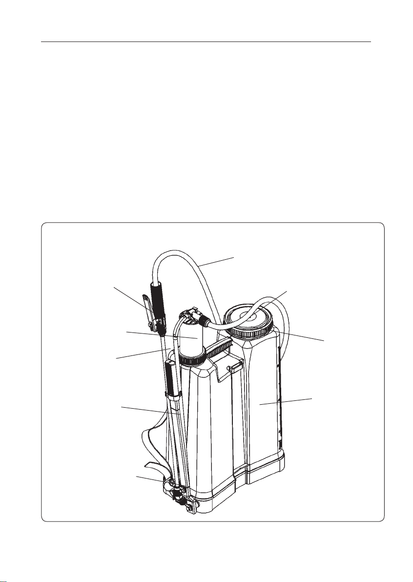
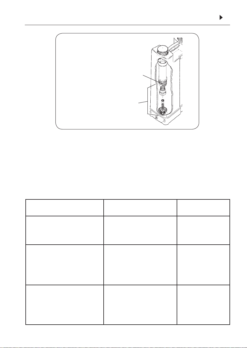
Lance / Lanza
Cover /Tapa
Filter / Filtro
Nozzle / Boquilla
Nozzle cap / Boquilla
Calibrator bottle / Calibrador
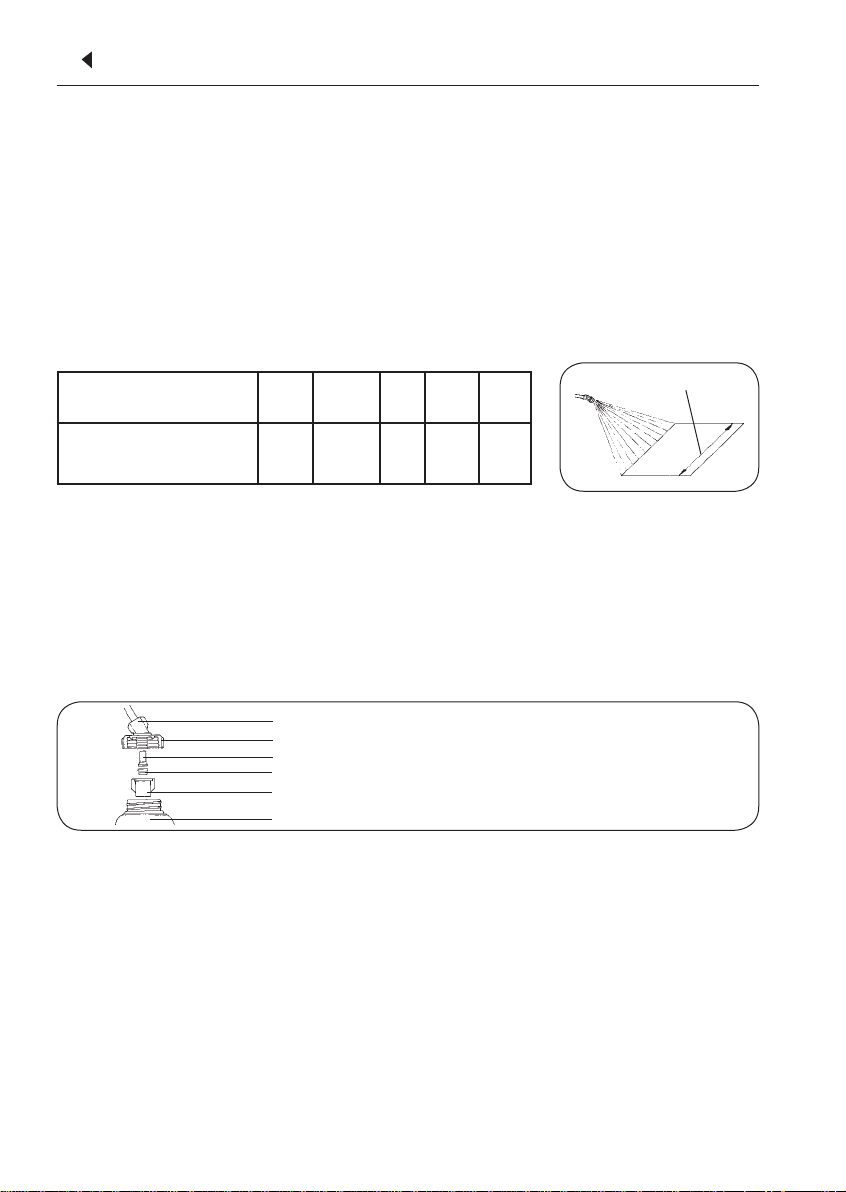
Band width / Franja
Band width (ft)
Ancho de la franja (ft) 1.6 2.2 3.2 3.9 4.9
Distance to walk (ft)
Distancia a recorrer (ft) 164 117.1 82 68.2 54.7
CALIBRATION OF MANUAL BACKPACK SPRAYER
CALIBRACIÓN DEL PULVERIZADOR
USING CALIBRATOR BOTTLE (optional) ∙ USO DEL CALIBRADOR
∙
Hold the lance at the working height and
spray to measure the application band
width. Based on the band width, calculate
the total walking distance required to spray
the desired area
269.1 sq/ft²
.
∙ Coloque la lanza en la altura de tra-
bajo y mida el ancho de la franja de
aplicación. De acuerdo con el ancho
de la franja de aplicación se debe re
-
correr una distancia que corresponda
a 269.1 sq/ft
.
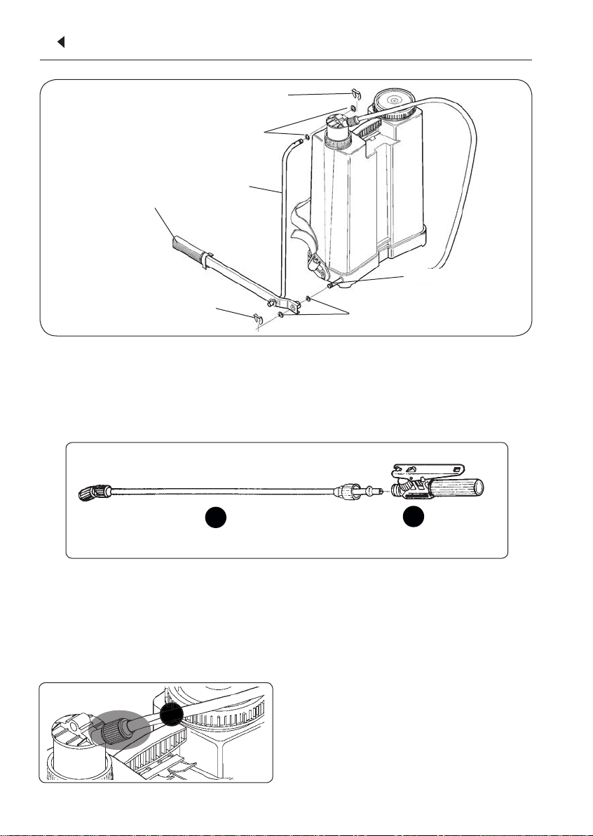
A - Remove the cap, nozzle and filter.
B - Mount the calibrator cover to the lance.
C - Reinstall the filter, nozzle and cap.
D - Screw the calibrator onto the cover.
A - Saque la tapa, la boquilla y el filtro.
B - Monte la tapa del calibrador.
C - Instale nuevamente la boquilla, el
filtro y la tapa.
D - Atornille el recipiente en la tapa.
∙ Attach the calibrator bottle to the lance as shown:
∙
Fije el calibrador a la tapa conforme sigue:
1510
∙ Hold the lance at the normal working hei-
ghtandsprayinto the bottle while walking
the distance required to spray an area cor-
respondingto269.1sq/ft².Placethebottle
on a level surface and observe the liquid
level visible through the side of the bottle.
Matchthe liquidlevelto thecorresponding
scale on the calibrator bottle. Empty the
bottle and repeat this operation to deter-
mine the average of two or more readings.
∙ Afirme la lanza en la posición normal
de trabajo y pulverice del recipiente
hasta cubrir el área correspondiente a
269.1 sq/ft²
. Mantenga el recipiente en
el nivel y haga la lectura. El nivel
del líquido indicará el volumen
en la escala correspondiente. Vacíe el
recipiente y repita la operación. Obten
drá el promedio de dos o más mediciones.
1∙ Enseguida coloque agua en el envase en
una cantidad aproximada a un cuarto de
su volumen total. Por ejemplo, para un
envase de 4 galóns, coloque 1 galón de
agua (Fig. A).
2∙Tape el envase cerrándolo bien para evitar
fugas mientras sea agitado.
3∙Agítelo bien, moviéndolo en todos los
sentidos por aproximadamente 30 se-
gundos para retirar los residuos de los
productos que permanezcan adheridos
en su interior.
4∙ Destape el envase y coloque el agua
del lavado en el tanque del pulveriza-
dor (Fig. B).
5∙ Mantenga el envase sobre la aber-
tura del tanque del pulverizador por
aproximadamente 30 segundos, hasta
vaciarlo totalmente.
6∙
Repita las operaciones de lavado más dos
veces, completando así el triple lavado.
7∙
Inutilice los envases plásticos y los metáli-
cos perforándoles el fondo con algún ins-
trumento puntiagudo. Así se evitará que
las etiquetas sean damnificadas e impidan
la identificación del tipo de producto
contenido y también que esos envases
sean usados nuevamente (Fig. C).
1∙ Next, hold the container in the upright
position and fill it with water up to 1/4
full. For example: in a 4 gallons container,
put 1 gallon of water (Fig. A).
2∙Fit the container cap and tighten it
enough to avoid leakage during the
agitation.
3∙Agitate the container strongly in all
directions (horizontal and vertical), for
approximately 30 seconds to remove the
residues that are sticked to the container
internal walls.
4∙Take the container cap off and carefully
pour the rinse water into the spray tank
(Fig. B).
5∙Continue holding the container over
the spray tank opening for approximate-
ly 30 seconds until the last drop.
6∙REPEAT this operation two more times
to complete the TRIPLE WASH.
7∙Make the plastic and metallic contain-
ers useless by piercing the container
bottom with a sharp pointed instrument.
This ensures the labels are not damaged
for identification purposes
(Fig. C).
Fig. A
Fig. B
Fig. C