3/68
1. Introduction
SAFETY GUIDELINES DEFINITIONS
This manual contains information for the proper assembly, op-
eration and care of your sprayer. Carefully read and follow the
instructions contained in this manual before using your sprayer.
This equipment was designed for spraying plants protection
products approved by regulatory authorities to be used in knap-
sack sprayers.
It is important for you to read and understand this manual. The infor-
mation it contains relates to protecting YOUR SAFETY and PREVENTING
PROBLEMS. The symbols below are used to help you recognize this in-
formation.
2. Specifications
Model HD 400/ 550
Net weight 3.7 kg/ 4.2 kg
Gross weight 4.3 kg/ 4.9 kg
Spray lance length 600 mm
Hose length 1650 mm
Chemical tank
Capacity 16 L/ 20 L
Filling opening diameter 115 mm
Material Polyethylene
Pump
Type Piston
Maximum working pressure 75 psi (5.1 bar)
Nozzle installed Blue adjustable cone
Material Polypropylene
DANGER!
Indicates an imminently hazardous situation which, if not avoid-
ed, will result in death or serious injury.
WARNING!
Indicates a potentially hazardous situation which, if not avoided,
could result in death or serious injury.
CAUTION!
Indicates a potentially hazardous situation which, if not avoided,
may result in minor or moderate injury.
Notice: Used without the safety alert symbol indicates a potentially haz-
ardous situation which, if not avoided, may result in property damage.
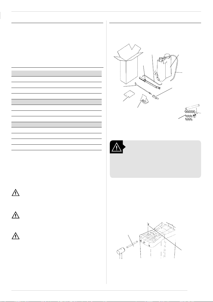
3.1. Unpacking
3. Preparing the Product For Use
Remove from the sprayer carton the following parts:
WARNING!
Be careful when taking out the sprayer out
of the carton because the lever is loose and
can cause damage or personal injury. Note
that the agitator is loose inside the tank and
must be properly assembly.
Manual
Haste Tank
Lance
Accessories
plastic bag Contents of the
plastic bag
Lever
Trigger
valve
Hose
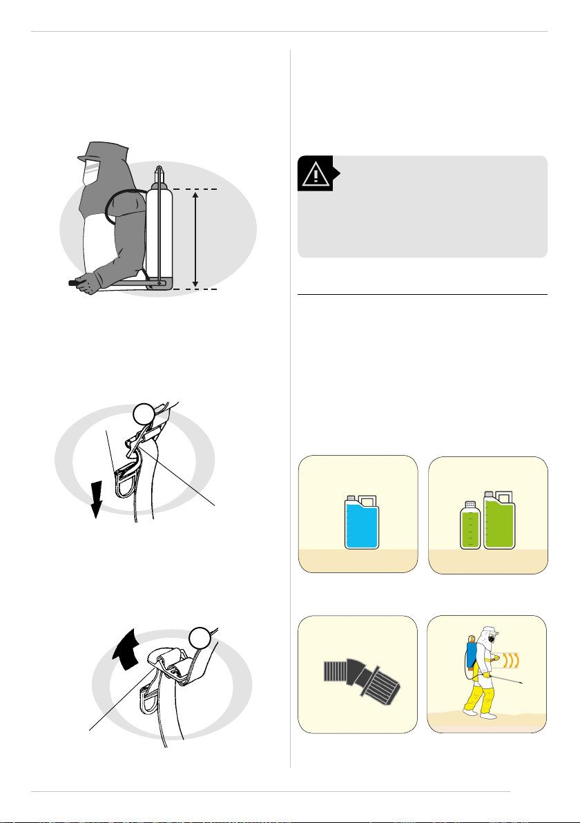
3.2. Installing the shaft
• Insert the shaft (1) in the free opening on the tank base (on
the same side of the chamber).Fit the shaft lock (2).
Shaft
(1)
Shaft
lock(2)
NOTE: Carton can be discarded in recyclable waste.
NOTE: Minimum space needed for use, maintenance and repair
is 1,5 m².
SAVE THESE INSTRUCTIONS: This manual contains important
safety instructions for the proper use and maintenance of this
product.