Jacto HP726 Owner's manual

WARNING!
This engine meets U.S. EPA PHASE 1 emission regulations for utility and lawn and garden equipment. This
engine is certified to operate on a 50:1 mixture consisting of unleaded gasoline and 2-cycle engine mixing
oil only. Please refer to this manual for all maintenance specifications and adjustments.
WARNING!
JACTO OWNER’S/OPERATORS MANUAL
HP726 HighPressure
BACKPACK ENGINE SPRAYER
Always wear the recommended
protective clothing and safety
equipment as recomended by the
chemical manufacturer when
spraying or handling chemicals
and when cleaning the sprayer. A
respirator, goggles, gloves, boots
and coveralls provide the
minimum protection.
To minimize the risk of injury to
yourself and others; Read and
follow this manual. In addition,
read and follow the chemical
manufacturer's instructions for
the products being applied.
Failure to do so could result in
serious injury!

1
Introduction
PAGE
The Jacto HP726 is designed and built
to deliver superior performance and
reliability without compromise to
quality, comfort, safety or durability.
Driven by a high-performance
Shindaiwa engine that represents the
leading edge of 2-cycle engine
technology, delivering exceptionally
high power with remarkable
efficiency.
IMPORTANT!
The information contained in these
instructions describes machines
available at the time of publication.
While every attempt has been made
to give you the very latest information
about your Jacto product, there may
be some differences between your
HP726 and what is described in this
manual. Jacto Inc. reserves the right
to make changes to products without
prior notice, and without obligation to
make alterations to previously manu-
factured machines.
Attention Statements........................... 2
Product Description ............................ 3
Specifications ....................................... 4
Basic Assembly .................................... 5
Spraying Operation ............................ 6
Mixing Fuel .......................................... 8
Starting the Engine ............................. 9
Stopping the Engine.......................... 11
Idle Speed Adjustment ...................... 11
Harness ............................................... 11
General Safety Instructions .............. 12
Maintenance ...................................... 14
Muffler ................................................ 17
Storage ................................................ 18
Troubleshooting Guide .................... 19
Emission System Warranty .............. 23
DESCRIPTION
WARNING!
The engine exhaust from this
product contains chemicals
known to the State of California
to cause cancer, birth defects or
other reproductive harm.
Contents

2
DESCRIPTION
Throughout this manual are special
statements surrounded by boxes and
preceded by special symbols.
IMPORTANT!
The operational procedures described
in this manual are intended to help
you get the most from your machine
as well as to protect you and others
from harm. These procedures are
guidelines for safe operation under
most conditions, and are not intended
to replace any safety rules and/or laws
that may be in force in your area.
If you have questions regarding
your HP726 Engine Sprayer or if you
do not understand something in this
manual, your Jacto dealer will gladly
assist you.
You may also contact Jacto, Inc. at
the address printed on the back of this
Manual.
WARNING!
A statement preceded by the word
“WARNING” contains information
that should be acted upon to
prevent serious bodily injury.
CAUTION!
A statement preceded by the word
“CAUTION” contains information
that should be acted upon to
prevent mechanical damage.
Additional attention statements that
are not preceded by the Attention
Symbol are:
IMPORTANT!
A statement preceded by the word
“IMPORTANT” is one that possesses
special significance.
READ AND FOLLOW THIS
MANUAL. FAILURE TO DO
SO COULD RESULT IN
SERIOUS INJURY.
WEAR EYE AND HEARING
PROTECTION AND A PARTICLE
RESPIRATOR AT ALL TIMES
DURING THE OPERATION
OF THIS UNIT.
DO NOT OPERATE THIS TOOL
IF YOU ARE TIRED, ILL OR
UNDER THE INFLUENCE OF
ALCOHOL, DRUGS, OR
MEDICATION.
Attention Statements

3
DESCRIPTION
Product Description
Using the accompanying illustrations
as a guide, familiarize yourself with
your machine and its various compo-
nents. Understanding your machine
helps ensure top performance, long
service life, and safer operation.
See figure 1.
WARNING!
Do not make unauthorized
modifications or alterations to any
of these units or their components.
Figure 1
Tank Lid
Wand
Storage
Clip
Pump Pressure
Control
Throttle
Control
Stop Switch
Spray Nozzles
Wand
Trigger Valve
Fuel Tank
Engine
Chemical
Tank

4
Specifications
HP726 Dry Weight ............................................................................. 9.2 kg/20.2 lbs.
Engine Model ..................................................................................... Shindaiwa S230
Engine Type ...................................................... 2-cycle, vertical-cylinder, air-cooled
Bore x Stroke ................................................................... 32 x 28 mm/1.26 x 1.10 in.
Displacement ................................................................................. 22.5 cc/1.4 cu. in.
Maximum Power Output .............................................. 0.8 kW/1.1 HP @ 7500 rpm
Fuel/Oil Ratio ............................50:1 with Shindaiwa Premium 2-cycle Engine Oil
Fuel Tank Capacity ............................................................................ 600 ml/20.3 oz.
Carburetor Type ...................................................... TK slide valve, diaphragm-type
Transmission Type ............. Automatic,centrifugal clutch through gear reduction
Ignition .......................................................... Fully electronic, transistor-controlled
Spark Plug .............................................................................................. NGK BMR6A
Air Cleaner Type ............................................. Foam element,quick-remove/install
Starting Method ................................................................................................. Recoil
Stopping Method .................................................................................. Toggle switch
Spayer Pump Type .......................................................... Horizontal duplex plunger
Three Stage Pump Pressure Range .............. 10, 20, 25 kgf/cm2/142, 284, 357 psi
Maximum Pump Pressure ........................................................ 25 kgf/cm2/357 psi
Chemical Tank Capacity ............................................................... 26 liters/7 gallons
DESCRIPTION
Prior to Assembly
The HP726 engine sprayer is shipped
in one carton. Before assembling your
HP726, make sure you have all the
components required for a complete
unit:
!Engine, pump and chemical tank
assembly
!Sprayer hose
!Trigger valve
!Spray wand
!Two head spray nozzle assembly
Super 25 and (D-3) nozzles (2 ea.)
!This manual and tool kit for routine
maintenance.
Carefully inspect all components for
damage.
IMPORTANT!
The terms “left”, “left-hand”, and “LH”;
“right”, “right-hand”, and “RH”; “front”
and “rear” refer to directions as
viewed by the operator during normal
operation.
*Specifications are subject to change without notice.

5
ASSEMBLY
2. Mount the spray hose, trigger valve,
spray wand and nozzles firmly to
the discharge outlet on the pump.
See figure 3.
3. Keep the trigger valve closed
(released) until the spraying
operation has started. See figure 4.
Figure 2
Figure 3
1. Assemble the sprayer hose, Trigger
assembly, wand and nozzles as
shown . See figure 2.
Figure 4
Trigger
Release Lever
Filling The Chemical Tank
Figure 5
1. Place the HP726 Engine spayer on a
level surface. Unscrew the chemi-
cal tank cap counter clockwise.
See figure 5.
2. Pour chemical mix through strainer
only. See figure 6.
Figure 6
WARNING!
Clean all chemical spills immedi-
ately! Dispose of any residue in
accordance with all local, state and
federal laws and regulations.
ASSEMBLY
Counter Clockwise to Remove

6
Spraying Operation
OPERATION
Before each use of the HP726,
always check the following:
!Make sure the chemical tank
lid is installed and tightened
firmly but do not over tighten.
!Make sure that the sprayer
hose connections at the pump
and the trigger valve are
secure.
! Make sure that the trigger
valve is in the closed position.
! make sure that the spray
wand and nozzles are properly
assembled and secure.
The sprayer pump pressure control
valve has four "preset" pressure
settings. As the pressure control valve
knob is rotated, a detent spring can be
felt holding the knob at each setting.
The preset pressure settings are 0 for
no pressure, (used during engine
starting), 1 for 142 psi (10 kgf/cm2)
pump pressure, position 2 for 284 psi
(20 kgf/cm2) and position 3 for 357 psi
(25 kgf/cm2). Refer to the following
chart for the proper pump control
valve settings:
The engine and pump are connected
by a centrifugal clutch. At engine idle
the clutch is disengaged and the
pump is not operating. To reduce the
risk of clutch slippage and inconsis-
tent application rates, never operate
the HP726 at low engine speeds.
IMPORTANT!
Pump Control Pump Recommended
Valve Setting Pressure Application
0 0 psi Engine start.
1 142 psi For low pressure spraying
(10 kgf/cm
2
) of herbicide.
2 284 psi For general spraying
(20 kgf/cm
2
) operations.
3 357 psi For high pressure spraying
(25 kgf/cm
2
) or extended hose length
operations.
WARNING!

7
Super Angle (dual nozzles)
Super 25 (dual nozzles)
liters per minute
Pump and Nozzle Performance Chart
8
7
6
5
4
3
2
1
071
(5)
142
(10)
213
(15)
284
(20)
357 psi
(25 kgf/cm2)
NOTE:
The pressure during spraying varies
according to nozzle discharge rate.
For most agri-chemical applications,
the spraying pressure variance will be
nominal and is dependent on nozzle
orifice size.
OPERATION
The HP726 is supplied with two sets of
spraying nozzles, Super Angle (D-3)
and Super 25. The discharge rates are
shown in the following pump/nozzle
performance chart.
Figure 7
Super 25
Super Angle (D-3)
The HP726 spayer is supplied with two
sets of spraying nozzles, Super Angle
(D-3) and Super 25. See figure 7 for
proper assembly orientation.

8
Mixing Fuel
CAUTION!
Some types of gasoline contain
alcohol as an oxygenate.
Oxygenated gasoline may
cause increased operating
temperatures. Under certain
conditions, alcohol-based
gasoline may also reduce the
lubricating qualities of some 2-
cycle mixing oils. Never use
any type of gasoline containing
more than 10% alcohol by
volume!
Generic oils and some out-
board oils may not be intended
for use in high-performance 2-
cycle engines, and should
never be used in your Shin-
daiwa engine.
IMPORTANT!
This engine is certified to operate
on a 50:1 mixture consisting of
unleaded gasoline and 2-cycle
mixing oil only. Mix only enough
fuel for your immediate needs! If
fuel must be stored longer than 30
days, it should first be treated with a
stabilizer such as StaBiI™.
!Mix fuel by combining unleaded
gasoline with Shindaiwa Premium
2-cycle Engine Oil at a ratio of
50:1 (a gallon of gasoline mixed
with 2.6 fl. oz. of 2-cycle mixing oil
or 5 liters of gasoline with 100 ml
of 2-cycle mixing oil).
!Use only fresh, clean, unleaded
gasoline with an octane rating of
87 or higher.
Filling the Fuel Tank
WARNING!
Minimize the risk of fire!
!Always allow the engine to
cool before refueling!
!Wipe all spilled fuel and move
the engine spayer at least 10
feet (3 meters) from the
fueling point and source
before restarting!
!Never smoke or light any fires
near the engine sprayer or
fuel source!
!Never place any flammable
material near the engine
muffler!
!Never operate the engine
without the muffler and spark
arrester in good working
condition.
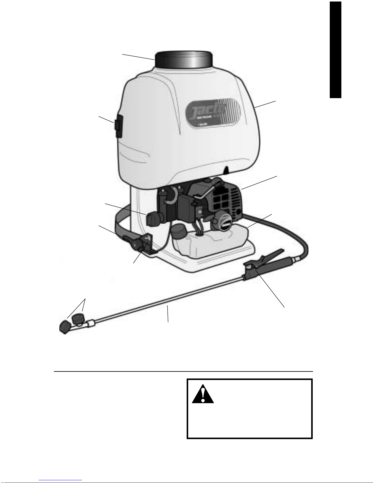
1. Place the HP726 engine sprayer on
a flat, level surface.
2. Clear any dirt or other debris from
around the fuel filler cap.
3. Remove the fuel cap, and fill the
tank with clean, fresh fuel.
4. Reinstall the fuel filler cap and
tighten firmly.
OPERATION

9
OPERATION
Figure 8
2. Always make sure that the sprayer
wand trigger is closed. (released)
See figure 8.
Figure 9
3. Rotate the sprayer pump pressure
control valve to the "START:0"
position. See figure 9.
Starting the Engine
CAUTION!
Never start the engine without
liquid in the chemical tank!
Running the engine without liquid
in the chemical tank can cause
severe sprayer pump damage.
4. Set the toggle switch to the "ON"
position. See figure 10.
5. Set the throttle lever to the idle
position. See figure 10.
Figure 11
6. Press the primer bulb on the
carburetor until fuel fills the bulb
and constant pressure is felt as the
bulb is pressed. See figure 11.
IMPORTANT!
The primer system only pushes fuel
through the carburetor. Repeatedly
pressing the primer bulb will not flood
the engine with fuel.
Pump
Pressure
Control
Valve
Figure 10
Ignition "ON"

10
Figure 12
7. Set the choke lever to the closed
position. See figure 12.
Figure 13
8. Hold the HP726 firmly with one
hand. Slowly pull the recoil starter
handle until resistance is felt, then
pull quickly to start the engine.
See figure 13.
Starting the Engine (Cont.)
CAUTION!
Do not pull the recoil starter to the
end of the rope travel. Pulling the
recoil starter to the end of the rope
travel can damage the starter.
9. When the engine starts, slowly
move the choke lever to the
"OPEN" position. If the engine
stops after the initial start, close the
choke and restart. See figure 14.
IMPORTANT!
If the engine fails to start after
several attempts with the choke in
the closed position, the engine may
be flooded with fuel. If flooding is
suspected, move the choke lever to
the open position and repeatedly pull
the recoil starter to remove excess
fuel and start the engine.
If the engine still fails to start, refer to
the troubleshooting section of this
manual.
Figure 14
Choke Closed
Choke Open
OPERATION

11
OPERATION
Idle the engine briefly, then move the
ignition toggle switch to the "OFF"
position. See figure 15.
The idle speed must be adjusted so
the clutch will fully disengage at
engine idle, causing the pump to stop
oscillating.
Check and Adjust Idle Speed
1. Start the engine and allow it to
warm up at low rpm.
2. If the pump oscillates at engine
idle, reduce idle speed by turning
the idle adjusting screw counter-
clockwise. See figure 17.
NOTE:
Standard idle speed is
3000, rpm +/– 250 rpm.
Stopping the Engine
Adjusting Engine Idle
WARNING!
The pump must NEVER oscillate
at engine idle.
WARNING!
Fuel mixture has been preset at
the factory and further adjust-
ment should be made only by
your Shindaiwa authorized
dealer.
Figure 15
Ignition "OFF"
Figure 17
Idle Speed
Screw
Harness
Figure 16
Make sure all hooks and adjusting
devices are secure.To adjust the
straps, either lift up on the buckles to
release or legthen, or grasp the loops
at the ends of the straps and pull to
shorten. Adjust the harness shoulder
straps so the sprayer rests comfortably
flat against your back. See figure 16.

12
The Properly Equipped Operator (general)
Always wear a
respirator while
spraying chemicals.
Wear close-fitting
clothing such as
long sleeve shirts
and long pants to
protect legs and
arms. Gloves
offer added
protection and are
strongly recom-
mended. Do not
wear clothing or
jewelry that could
get caught in
machinery
or underbrush.
Secure long hair
so that it is above
shoulder level.
Wear hearing protection devices and a
broad-brimmed hat or helmet.
Always wear eye
protection such as
goggles or safety
glasses.
Wear appropriate foot-
wear (non-skid boots): do
not wear open-toed shoes
or sandals. Never work
barefooted!
Keep a proper footing and do not
overreach—maintain your balance at
all times during operation.
Figure 18
Keep wand pointed in a
safe direction at all times.
NEVER spray anything
that you don't intend to
apply chemical to.
Avoid long-term
operation in very hot
or very cold weather.
Be extremely careful of slippery
terrain, especially during rainy
weather.
OPERATION
Always
wear gloves
while spraying or
handling chemicals.

13
Work Safely
High pressure sprayers operate at
very high speeds and pressure and
can cause serious damage or injury if
they are misused or abused. Never
allow a person without training or
instruction to operate this machine!
WARNING!
Use Good Judgment
ALWAYS carefully read and
follow the information provided
with the chemical before proceed-
ing.
NEVER run the engine indoors!
Make sure there is always good
ventilation. Fumes from engine
exhaust can cause serious injury
or death.
ALWAYS wear the recommended
protective clothing as directed by
the chemical manufacturer when
spraying or handling chemicals
and when cleaning the sprayer. A
respirator, goggles, gloves, boots
and coveralls provide the mini-
mum protection.
ALWAYS wash thoroughly after
spraying or handling chemicals.
Shower immediately and wash all
protective clothing and equip-
ment separately.
In case of accidental contact or
ingestion of chemicals, stop work
and see a doctor immediately.
Show the doctor the
manufacturer's label from the
chemical(s) involved.
NEVER use any hose, trigger
valve or spray wand that is
leaking or otherwise defective!
READ and follow this manual. In
addition, read and follow the
chemical manufacturer's instruc-
tions for the products being
applied. Failure to do so could
result in serious injury!
CLEAN all chemical spills
immediately! Dispose of any
residue in accordance with all
local, state and federal laws and
regulations.
OperatorSafety (Safety Precautions)
WARNING!
Never operate power
equipment of any kind if
you are tired or if you are under
the influence of alcohol, drugs, or
any other substance that could
affect your ability or judgement.
WARNING!
Minimize the Risk of Fire
NEVER smoke or light fires near
the engine sprayer.
ALWAYS stop the engine and
allow it to cool before refueling.
Avoid overfilling and wipe off any
fuel that may have spilled.
ALWAYS move the unit to a place
well away from a fuel storage area
or other readily flammable
materials before starting the
engine.
NEVER place flammable material
close to the engine muffler.
NEVER run the engine without
the spark arrester screen in place.
ALWAYS keep the unit as clean as
practical. Keep it free of loose vegeta-
tion, mud, etc. Rinse inside and
outside of machine regularly.
ALWAYS stop the machine immedi-
ately if it suddenly begins to vibrate or
shake. Inspect for broken, missing or
improperly installed parts or attach-
ments.
ALWAYS disconnect the spark plug
wire before performing any
maintenance work.
OPERATION

14
WARNING!
Using non-standard replacement
parts could invalidate your
product warranty. Non-standard
parts may not operate properly
with your unit and may cause
damage and lead to personal
injury.
Muffler
This machine must never be operated
with a faulty or missing spark arrester
or muffler. Make sure the muffler is well
secured and in good condition. A worn
or damaged muffler is a fire hazard and
may also cause hearing loss.
Spark Plug
Keep the spark plug and wire connec-
tions tight and clean.
Fasteners
Make sure nuts, bolts, and screws
(except carburetor adjusting screws)
are tight.
Maintenance
WARNING!
Before performing any mainte-
nance, repair, or cleaning work on
the machine, make sure the engine
is completely stopped. Disconnect
the spark plug wire before perform-
ing service or maintenance work.
Daily Maintenance
Prior to each work day, perform the
following:
!Remove all dirt and debris from the
engine, check the cooling fins and
air cleaner for clogging, and clean
as necessary.
!Carefully remove any accumulations
of dirt or debris from the muffler and
fuel tank. Dirt build-up in these areas
can lead to engine overheating, fire,
or premature wear.
!Check for loose or missing screws or
components. Make sure the sprayer
hose is securely fastened.
!Check the entire machine for
leaking fuel or grease.
Periodic Maintenance
ANY REPAIR ESTABLISHMENT OR
INDIVIDUAL MAY PERFORM
MAINTENANCE, REPLACEMENT,
OR REPAIR OF EMISSION CON-
TROL DEVICES AND SYSTEM.
HOWEVER, WARRANTY REPAIRS
MUST BE PERFORMED BY A
DEALER OR SERVICE CENTER
AUTHORIZED BY JACTO INC. THE
USE OF PARTS THAT ARE NOT
EQUIVALENT IN PERFORMANCE
AND DURABILITY TO AUTHO-
RIZED PARTS MAY IMPAIR THE
EFFECTIVENESS OF THE EMIS-
SION CONTROL SYSTEM AND
MAY HAVE A BEARING ON THE
OUTCOME OF THE WARRANTY
CLAIM
Checking Unit Condition
ALWAYS make sure the trigger valve,
spray wand and nozzles are properly
installed and firmly tightened before
operation.
NEVER operate the sprayer with a
damaged hose or trigger valve
assembly.
NEVER operate a machine with worn
or damaged fasteners.
NEVER operate the unit with protec-
tive devices (harness, ignition switch,
trigger valve, etc.) removed!
MAINTENANCE

15
10-Hour Maintenance
Every 10 to 15 hours of operation:
Remove and clean the spark plug.
Adjust the spark plug electrode gap to
0.024-inch (0.6 mm). If the plug must be
replaced, use a NGK BMR6A.
See figure 20.
Before removing the spark plug,
clean the area around the plug to
prevent dirt and dust from getting
into the engine’s internal parts.
Clean the spark plug and check
the gap at the electrode.
Counter-
Clockwise to
Loosen Remove and clean
the element
Every 10 hours of operation (more
frequently in dusty or dirty condi-
tions):
Remove the air cleaner element from
the carburetor and clean it thoroughly
with soap and water, let dry and
reassemble the element.
See figure 19.
CAUTION!
Do not operate the machine if the
air cleaner or element is dam-
aged, or if the element is wet or
watersoaked
10/15-Hour Maintenance
Figure 19
Figure 20
27030
0.024-inch
(0.6 mm)
CAUTION!
MAINTENANCE

16
MAINTENANCE
50-hour Maintenance
Every 50 hours of operation
(more frequently in dusty or dirty
conditions):
Use a hooked wire to extract the fuel
filter from inside the fuel tank. See
figure 22. Remove and replace the
filter element if necessary. Before
reinstalling the filter, inspect the
condition of the fuel line. If damage or
deterioration are noted, the HP726 unit
should be removed from service until
it can be inspected by a Jacto-trained
service technician.
Filter Element
Figure 22
Hooked
Wire
Figure21
Lubrication points
Remove back pad and lubricate at the
points shown with a few drops of light
weight machine oil. See figure 21.
Figure 23
Lubricate pump pressure control cam
with a small amount of lithium based
grease. See figure 23.
Lubrication
Point
Figure 24
Remove chemical tank vent from cap
and clean with warm soapy water. Let
dry thoroughly and reassemble
Replace foam element if damaged.
Replace element every two years.
See figure 24.
Tank Vent
(installed)
Foam
Element and
retainer

17
MAINTENANCE
Muffler
Hard starting or a gradual loss of
performance can be caused by carbon
deposits lodged in the muffler’s spark
arrester screen.
In such cases, performance can
usually be restored by removing the
arrester screen and giving it a thor-
ough cleaning with a stiff bristle
brush.
If carbon deposits are severe or if
no performance improvement is
noted, your HP726 should be returned
to your Jacto dealer for inspection.
WARNING!
Never operate this machine with
a damaged or missing muffler or
spark arrester! Operating with
missing or damaged exhaust
components is a fire hazard, and
could also damage your hearing.
Figure 25
Loosen the engine cover retaining
knob counter-clockwise and lift the
cover from the engine. See figure 25.
Figure 26
Remove the spark arrester retention
screw using a Phillips screwdriver.
See figure 26.
Figure 27
Remove the spark arrester from the
muffler and clean with a stiff bristled
brush. If the spark arrester is dam-
aged in any way, replace with a new
one. See figure 27.

18
CAUTION!
Gasoline stored in the carburetor
for extended periods can cause
hard starting, and could also lead
to increased service and mainte-
nance costs.
Long Term Storage
Whenever the machine will not be
used for 30 days or longer, use the
following procedures to prepare it for
storage:
!Clean external parts thoroughly
and apply a light coating of oil to all
metal surfaces.
!Drain all the fuel from the carbure-
tor and the fuel tank.
IMPORTANT!
All stored fuels should be stabilized
with a fuel stabilizer such as
STA-BIL姞.
!Remove the spark plug and pour
about 1/4 ounce of oil into the
cylinder through the spark plug
hole. Slowly pull the recoil starter 2
or 3 times so oil will evenly coat the
interior of the engine. Reinstall the
spark plug.
!Before storing the machine, repair
or replace any worn or damaged
parts.
!Remove the air cleaner element
from the carburetor and clean it
thoroughly with soap and water, let
dry and reassemble the element.
!Store the machine in a clean, dust-
free area.
Short Term Storage
To remove any remaining chemical
solution from the tank, place a suitable
container under the chemical tank
drain and remove the cap.
See figure 28.
Dispose of any unused chemicals
properly following the chemical
manufacturer instructions and any
enviromental regulations in your area.
!Drain and rinse the chemical tank
with clean water.
!Add clean water into the tank and
run the engine sprayer momen-
tarily to flush pump, hose and wand
to remove any residual chemicals
within the machine prior to storage.
!Drain any remaining water from
the tank as previously described,
then open the pump drain and
allow any residual water to drain
from the pump. This is also
recomended for long term storage
and to prevent freezing when air
temperatures are 320F (00C) or
below.
Figure 28
Tank
Drain
Cap
Pump Drain

19
TROUBLESHOOTING
HP726 Troubleshooting Guide (Engine)
ENGINE DOES NOT START
Does the engine
crank?
Faulty recoil starter.
Fluid in the crankcase.
Internal damage.
Consult with an authorized
servicing dealer.
NO
Good
compression?
Loose spark plug.
Excess wear on
cylinder, piston, rings.
Tighten and re-test.
Consult with an authorized
servicing dealer.
NO
YES
Does the tank
contain fresh
fuel of the
proper grade?
Re-fill with fresh fuel of
the correct mixture
(gasoline and Shindaiwa
Premium 2-cycle Engine
Oil gasoline, 50:1 ratio.
Fuel incorrect, stale, or
contaminated; mixture
incorrect.
NO
YES
Is fuel visible
and moving in
the return line
when priming?
Check for clogged fuel
filter and/or vent.
Clean as required;
restart.
NO
Is there spark at
the spark plug
wire terminal?
The ignition switch
is in “O” (OFF) position.
Faulty ignition ground.
Faulty transistor unit.
Move switch to "ON"
position and re-start.
NO
YES
YES
Check the
spark plug
If the plug is wet, excess
fuel may be in the
cylinder.
The plug is fouled
or improperly gapped.
The plug is damaged
internally or of the
wrong size.
Crank the engine with the
plug removed, replace the
plug, and re-start.
Clean and re-gap the plug to
0.24 inch (0.6 mm). Re-start.
Replace the plug with a
NGK BMR6A Re-start.
YES
What To Check Possible Cause Remedy
Consult with an authorized
servicing dealer.
Table of contents
Other Jacto Paint Sprayer manuals

Jacto
Jacto ARBUS 1000 User manual

Jacto
Jacto SP 312 User manual

Jacto
Jacto PJBc Series User manual

Jacto
Jacto DJB-20S User manual

Jacto
Jacto PJB User manual

Jacto
Jacto CONDOR B-12 User manual

Jacto
Jacto PJB-20/16 User manual

Jacto
Jacto ARBUS 500 User manual

Jacto
Jacto PJH User manual

Jacto
Jacto hh-5 User manual