Jacto DJB-20S User manual

Operator’s Manual - English
DJB-20S
Manual de Instruções - Português (19)
Manual del Operador - Español (34)
Code: 1249054 / Date: 12-2019 / Edition: 1
Customer attendance: Dr. Luiz
Miranda, 1650, 17580-000 –
Pompeia – SP – Brasil.
Phone: +55 14 3405 2113. Email:
assistencia.tecnicajsfs@jacto.com.br
Opening Hours: Monday to Friday
7:00am to 11:30am and 13:00pm to
17:18pm (Brazilian time zone).
Manufactured by INTERMAN Corporation Ltd.
under license of Máquinas Agrícolas Jacto S.A.
Rojana Industrial Park (Rayong)
3/3, Moo 2, Bankhai-Banbueng Rd.T. Nongbua.
A.Bankhai Rayong 21120 -Thailand
com.br
CAUTION: IT IS MANDATORY
TO READ AND THOROUGHLY
UNDERSTANDTHE OPERATOR’S
MANUAL BEFORE USINGTHE
EQUIPMENT.
Knapsack Sprayer Jacto

1. Introduction 4
2. Specifications 4
3. General Power Tool Safety Warnings 4
Work area safety / Electrical safety / Personal Safety /
Power tool use and care / Battery tool use and care / Service
4. Symbols 5
5. Important Safety Instructions for Battery Chargers 5
Charging procedure / Important charging notes
6. Important Safety Instructions for Battery Packs 6
Storage recommendations for batteries
7. Important Safety Instructions for Sprayers 7
Triple rinse of empty agrochemicals containers
8. Preparation for use 7
Unpacking / Assembling the lance to the trigger valve /
Assembling the hose to the sprayer / Installing the electric
cord in the hose / Shoulder strap adjust / Installing and
removing the battery
9. Operating Instructions 8
Choosing nozzle type / Pressure, flow rate and autonomy of
each nozzle type / Electronic panel / Jacto Smart Control
App / DJB (Doser) / Turning ON/OFF the doser function and
selecting the dose / Measuring the dose / Possible Doses /
Possible time intervals / Turning ON/OFF the panel lock /
Turning ON/OFF the agitation system / Turning ON/OFF the
sprayer function and selecting the pressure level /
Configuring the step indicator / Calibration of battery
powered knapsack sprayer / Preparing the agrochemical
solution and filling the tank / Application / EPI / Influence of
climatic conditions
10. Maintenance and Storage 14
Agitation system maintenance / Lubricating the agitation
system / Quick coupler maintenance and lubrication
11. Accessories (optional) 15
Anti-growth lance / Calibration jug / Extension 600 / Nozzle
JD-40
12. Troubleshooting 17
13. Important Return Safety Instructions 18
14. Statement of Limited Warranty 18
Warranty period / Warranty application / This warranty shall
be null & void in case of / This warranty shall exclude /
General terms
15. Parts list 49
ÍNDICE
SUMMARY
1. Introdução 19
2. Especificações Técnicas 19
3. Alertas de Segurança para Ferramenta Elétrica em Geral 19
Segurança da área de trabalho / Segurança elétrica /
Segurança pessoal / Uso e cuidado da ferramenta elétrica /
Uso e cuidado da bateria / Serviço
4. Símbolos 20
5. Instruções de Segurança Importantes para Carregadores
de Bateria 20
Procedimento de recarga / Notas importantes de
carregamento
6. Instruções de Segurança Importantes para a Bateria 21
Recomendações de armazenamento para as baterias
7. Instruções de Segurança Importantes para
Pulverizadores 22
Tríplice lavagem de embalagens vazias de defensivos
8. Preparação para o uso 23
Desembalando / Montagem da lança mangueira e registro /
Montagem da mangueira no pulverizador / Fixando o cabo
elétrico na mangueira / Ajuste da cinta / Instalando e
removendo a bateria
9. Instruções de Operação 24
Escolhendo o tipo de bico / Pressão, vazão e autonomia de
cada tipo de bico / Painel eletrônico / Jacto Smart Control
App / DJB (Dosador) / Ligar/desligar a função dosador e
selecionar a dose / Aferição da dose / Possíveis doses
/ Possíveis intervalos de tempo / Ativar/desativar o bloqueio
de painel / Ativar/desativar o sistema de agitação /
Ligar/desligar a função pulverizador e selecionar o nível de
pressão / Configuração do marcador de passos / Calibração
do pulverizador / Preparo de calda e abastecimento do
tanque / Aplicação / EPI / Influência de condições climáticas
10. Manutenção e Limpeza 29
Manutenção do sistema de agitação / Lubrificação do
sistema de agitação
11. Acessórios (opcionais) 30
Lança antibrotante / Copo calibrador / Bico JD-40
12. Identificação de Problemas 32
13. Instruções de Segurança Importantes de Devolução 33
14. Termo de Garantia Limitada 33
Prazo de garantia / Aplicação da garantia / Perda do direito
de garantia / Itens excluídos da garantia / Termos gerais
15. Lista de peças 49

1. Introducción 34
2. Especificaciones Técnicas 34
3. Alertas de Seguridad para Herramientas Eléctricas en
General 34
Seguridad en el área de trabajo / Seguridad eléctrica /
Seguridad personal / Uso y cuidados de la herramienta
eléctrica / Uso y cuidado de la batería / Servicio
4. Símbolos 35
5. Instrucciones de Seguridad Importantes para Cargadores de
Batería 35
Procedimiento de recarga / Observaciones importantes
sobre carga
6. Instrucciones de Seguridad Importantes para la Batería 36
Recomendaciones para almacenamiento de baterías
7. Instrucciones de Seguridad Importantes para
Pulverizadores 37
Triple Lavado de envases vacíos de agroquímicos
8. Preparación para el uso 38
Desempacando / Montaje de la lanza en la válvula / Montaje
de la manguera en el pulverizador / Asegurando el cable
eléctrico en la manguera / Ajuste de la correa / Instalando y
sacando la batería
9. Instrucciones de Operación 39
Eligiendo el tipo de boquilla / Presión, caudal y autonomía de
cada tipo de boquilla / Panel electrónico / Jacto Smart
Control App / DJB (Dosificador) / Encender/apagar la función
dosificador y seleccionar la dosis / Verificación de la dosis /
Posibles dosis / Posibles intervalos de tiempo /
Activar/desactivar el bloqueo del panel / Activar/desactivar
el sistema de agitación / Encender/apagar la función
pulverizador y seleccionar el nivel de presión / Configuración
del marcador de pasos / Calibración del pulverizador /
Preparación del producto y llenado del tanque / Aplicación /
EPI / Influencia de condiciones climáticas
10. Mantenimiento y Almacenamiento 44
Mantenimiento del sistema de agitación / Lubricación del
sistema de agitación / Mantenimiento y lubricación del
enganche rápido.
11. Accesorios (opcional) 45
Lanza antibrotante / Extensión 600 / Boquilla JD-40
12. Solución de problemas 47
13. Instrucciones de Seguridad Importantes para
Devolución 48
14. Términos y Condiciones de Garantía Limitada 48
Plazo de garantía / Aplicación de la garantía / Pérdida del
derecho de garantía / Ítems excluidos de la garantía /
Términos generales
15. Lista de piezas 49
TABLA DE CONTENIDO

4/52
1. Introduction
SAFETY GUIDELINES – DEFINITIONS
SAVE THESE INSTRUCTIONS: This manual contains information for the proper
assembly, operation and care of your sprayer. Carefully read and follow the instruc-
tions contained in this manual before using your sprayer.
This equipment was designed for spraying plants protection products approved
by regulatory authorities to be used in knapsack sprayers.
The product may be subject to national requirements for regular inspection by
designated bodies, as provided for in Directive 2009/128/EC of the European
Parliament and of the Council of 21 October 2009 establishing a framework for
Community action to achieve the sustainable use of pesticides.
It is important for you to read and understand this manual. The information it
contains relates to protecting YOUR SAFETY and PREVENTING PROBLEMS. The
symbols below are used to help you recognize this information.
2. Specifications
3. General Power Tool Safety Warnings
Model DJB-20S
Maximum dimensions (L x W x H) 430 x 310 x 620 mm
Net weight 5,9 kg
Gross weight 6,6 kg
Spray lance length 600 mm
Hose length 1350 mm
Chemical tank
Capacity 20 L
Residual volume None
Filling opening diameter 115 mm
Material Polyethylene
Pump
Type Diaphragm
Maximum pressure 60 psi (4,1 bar)
Open ow 2.1 L/min
Nozzle installed JD-12
Battery
Type Lithium Ion, rechargeable
Rated Voltage 14.54 V (16.4 V max.)
Capacity 84.3 Wh (5800 mAh)
Recharge time 5h
Autonomy* 5 - 14h
WARNING!
Read all safety warnings and all instructions. Failure
to follow the warnings and instructions may result in
electric shock, re and/or serious injury.
DANGER!
Indicates an imminently hazardous situation which, if not avoided, will
result in death or serious injury.
WARNING!
Indicates a potentially hazardous situation which, if not avoided, could
result in death or serious injury.
NOTE: Used without the safety alert symbol indicates a potentially hazardous
situation which, if not avoided, may result in property damage.
SAVE ALL WARNINGS AND INSTRUCTIONS FOR FUTURE REFERENCE.
The term “power tool” in the warnings refers to your mains-operated (corded)
power tool or battery-operated (cordless) power tool.
3.1. Work area safety
a. Keep work area clean and well lit. Cluttered or dark areas invite accidents.
b. Do not operate power tools in explosive atmospheres, such as in the pres-
ence of ammable liquids, gases or dust. Power tools create sparks which
may ignite the dust or fumes.
c. Keep children and bystanders away while operating a power tool. Distrac-
tions can cause you to lose control.
3.2. Electrical safety
a. Power tool plugs must match the outlet. Never modify the plug in any
way. Do not use any adapter plugs with earthed (grounded) power tools.
Unmodied plugs and matching outlets will reduce risk of electric shock.
b. Avoid body contact with earthed or grounded surfaces such as pipes, ra-
diators, ranges and refrigerators. There is an increased risk of electric shock if
your body is earthed or grounded.
c. Do not expose power tools to rain or wet conditions. Water entering a pow-
er tool will increase the risk of electric shock.
d. Do not abuse the cord. Never use the cord for carrying, pulling or un-
plugging the power tool. Keep cord away from heat, oil, sharp edges or
moving parts. Damaged or entangled cords increase the risk of electric shock.
e. When operating a power tool outdoors, use an extension cord suitable
for outdoor use. Use of a cord suitable for outdoor use reduces the risk of electric
shock.
f. If operating a power tool in a damp location is unavoidable, use a ground
fault circuit interrupter (GFCI) protected supply. Use of a GFCI reduces the
risk of electric shock.
CAUTION!
Indicates a potentially hazardous situation which, if not avoided, may
result in minor or moderate injury.
3.3. Personal Safety
a. Stay alert, watch what you are doing and use common sense when oper-
ating a power tool. Do not use a power tool while you are tired or under
the inuence of drugs, alcohol or medication.A moment of inattention while
operating power tools may result in serious personal injury.
b. Use personal protective equipment. Always wear eye protection. Protec-
tive equipment such as dust mask, non-skid safety shoes, hard hat, or hearing
protection used for appropriate conditions will reduce personal injuries.
c. Prevent unintentional starting. Ensure the switch is in the o-position be-
fore connecting to power source and/or battery pack, picking up or car-
rying the tool. Carrying power tools with your nger on the switch or energizing
power tools that have the switch on invites accidents.
d. Remove any adjusting key (wrench, screwdriver…) before turning the
power tool on. A wrench or a key left attached to a rotating part of the power
tool may result in personal injury.
e. Do not overreach. Keep proper footing and balance at all times. This en-
ables better control of the power tool in unexpected situations.
f. Dress properly. Do not wear loose clothing or jewellery. Keep your hair,
clothing and gloves away from moving parts. Loose clothes, jewellery or long
hair can be caught in moving parts.
g. If devices are provided for the connection of dust extraction and collec-
tion facilities, ensure these are connected and properly used. Use of dust
NOTE: See item“9.2. Pressure, ow rate and autonomy of each nozzle type”.

5/52
collection can reduce dust-related hazards.
4. Symbols
The label on your tool may include the following symbols. The symbols and their
denitions are as follows:
V volts n0no-load speed
A amperes ou d.c. direct current
Wwatts ou a.c alternating current
Hz hertz earthing terminal
lbf/in² (lbf/pol²) psi l litres
min minutes kg kilograms
h hours m meters
3.4. Power tool use and care
a. Do not force the power tool. Use the correct power tool for your applica-
tion. The correct power tool will do the job better and safer at the rate for which
it was designed.
b. Do not use the power tool if the switch does not turn it on and o. Any
power tool that cannot be controlled with the switch is dangerous and must be
repaired.
c. Disconnect the plug from the power source and/or the battery pack from
the power tool before making any adjustments, changing accessories, or
storing power tools. Such preventive safety measures reduce the risk of starting
the power tool accidentally.
d. Store idle power tools out of the reach of children and do not allow per-
sons unfamiliar with the power tool or these instructions to operate the
power tool. Power tools are dangerous in the hands of untrained users.
e. Maintain power tools. Check for misalignment or binding of moving
parts, breakage of parts and any other condition that may aect the pow-
er tool’s operation. If damaged, have the power tool repaired before use.
Many accidents are caused by poorly maintained power tools.
f. Keep cutting tools sharp and clean. Properly maintained cutting tools with
sharp cutting edges are less likely to bind and are easier to control.
g. Use the power tool, accessories and tool bits etc., in accordance with
these instructions, taking into account the working conditions and the
work to be performed. Use of the power tool for operations dierent from those
intended could result in a hazardous situation.
3.6. Service
a. Have your power tool serviced by a qualied repair person using only
identical replacement parts. This will ensure that the safety of the power tool
is maintained.
3.5. Battery tool use and care
a. Recharge only with the charger specied by the manufacturer. A charger
that is suitable for one type of battery pack may create a risk of re when used with
another battery pack.
b. Use power tools only with specically designated battery packs. Use of
any other battery packs may create a risk of injury and re.
c. When battery pack is not in use, keep it away from other metal objects
like paper clips, coins, keys, nails, screws, or other small metal objects
that can make a connection from one terminal to another. Shorting the
battery terminals together may cause burns or a re.
d. Under abusive conditions, liquid may be ejected from the battery, avoid
contact. If contact accidentally occurs, ush with water. If liquid contacts
eyes, additionally seek medical help. Liquid ejected from the battery may
cause irritation or burns.
e. Do not use a battery pack or appliance that is damaged or modied.
Damaged or modied batteries may exhibit unpredictable behavior re-
sulting in re, explosion or risk of injury.
f. Do not expose a battery pack or appliance to re or excessive tempera-
ture. Exposure to re or temperature above 60°C may cause explosion.
WARNING:
Shock hazard. Do not allow any liquid to get inside charger.
5. Important Safety Instructions for Battery
Chargers
SAVE THESE INSTRUCTIONS:
This manual contains important safety instructions
for battery chargers. Before using charger, read all instructions and cautionary
markings on charger, battery pack, and product using battery pack.
WARNING!
• DO NOT attempt to charge the battery pack with
any chargers other than the ones in this manual.
The charger and battery pack are specifically designed
to work together.
• Thesechargersare not intendedforanyuses other
thanchargingdesignatedJACTOlithiumrecharge-
able batteries.
Any other uses may result in risk of fire,
electric shock or electrocution.
• Do not expose charger to rain or snow.
• Pull by plug rather than cord when disconnecting
charger.
This will reduce risk of damage to electric
plug and cord.
• Make sure that cord is located so that it will not be
stepped on, tripped over, or otherwise subjected
to damage or stress.
• Donot use anextensioncordunlessit is absolutely
necessary.
Use of improper extension cord could result
in risk of fire, electric shock, or electrocution.
• An extension cord must have adequate wire size
(AWG or American Wire Gauge) for safety.
When
using more than one extension to make up the total
length, be sure each individual extension contains at
least the minimum wire size. When using an extension
cord, be sure to use one heavy enough to carry the
current that product will draw. An undersized cord will
causea dropinlinevoltage resultinginlossofpowerand
overheating. The following table shows the correct size
to use depending on cord length and nominal current
presented in the label of the charger mentioned in this
manual. If in doubt, use the next heavier gauge.
CAUTION!
• Burn hazard. To reduce the risk of injury, charge only
designated JACTO batteries. Other types of batteries
may burst causing personal injury and damage.
• Under certain conditions, with the charger plugged
in to the power supply, the charger can be shorted
by foreign material. Foreign materials of a conductive
naturesuch as,butnotlimitedto,steelwool,aluminum
foil, or any buildup of metallic particles should be kept
awayfromchargercontacts.Alwaysunplugthecharger
from the power supply when not charging battery.
Unplug charger before attempting to clean.
Extension Cord
Total Length
Up to
15.2 m
From 15.2 m
and up to 30 m
More than 30 m
Wire Size (AWG) 16 14
Not recommended
Wire Size (mm2)
1.5 2.5
Not recommended

6/52
• Do not mount charger on wall or permanently ax
chargerto anysurface.
The chargerisintended touseon
a flat, stable surface (i.e., table top, bench top).
• Do not operate charger with damaged cord or plug
-
have them replaced immediately.
• Do not operate charger if it has received a sharp
blow, been dropped, or otherwise damaged in any
way.
Take it to an authorized service center.
• Do not disassemble charger;
take it to an authorized
service center when service or repair is required. Incorrect
reassembly may result in a risk of electric shock, electro-
cution or fire.
• Disconnect the charger from the outlet before at-
temptinganycleaning.
Thiswillreducetheriskofelectric
shock. Removing the battery pack will not reduce this risk.
• NEVER attempt to connect 2 chargers together.
• The charger is designed to operate on standard
household electrical power. Do not attempt to use
it on any other voltage.
• Battery chargers contain electronic parts.
Dispose
of properly.
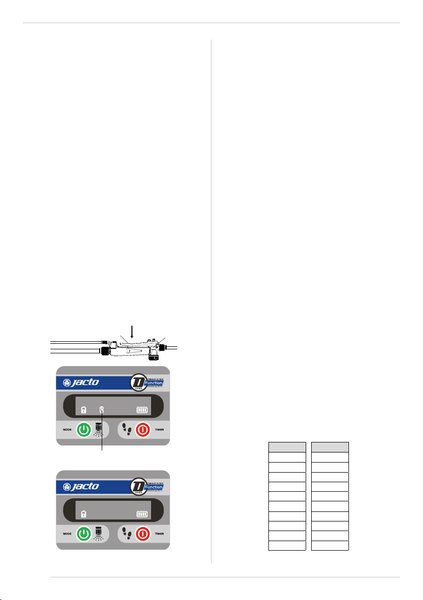
5.1. Charging procedure
JACTO charger supplied with this sprayer is designed to charge JACTO batteries of
the JB line. The JB1680 model is charged in 5 hours.
1. Remove the battery from the sprayer.
2. Plug the charger into an appropriate outlet before connecting the battery
pack. Make sure the AC cord is well attached to the charger.
3. Connect the charger plug to the battery pack connector.
4. The charge light will remain red/orange while charging.
5. When battery pack is fully charged, charge light will change its color to
green.
6. As soon as the battery is fully charged, disconnect the battery from the
charger.
7. Unplug charger cord from outlet.
Recharge discharged batteries as soon as possible or battery life may be
greatly diminished. For longest battery life, do not discharge batteries fully.
It is recommended that the batteries be recharged after each use.
5.2. Important charging notes
• DO NOT charge the battery pack in an air temperature below 0°C or above
45°C. This is important and will prevent serious damage to the battery pack.
• The charger and battery pack may become warm to the touch while charging.
This is a normal condition, and does not indicate a problem. To facilitate the
cooling of the battery pack after use, avoid placing the charger or battery pack
in a warm environment such as in a shed.
• Do not freeze or immerse charger in water or any other liquid.
WARNING:
For safe operation, read this manual and manuals
originally supplied with tool before using the charger.
Whenopeningthetoolpackageforthefirst time,thebattery
packwill not befullycharged.Beforeusingthebatterypack
andcharger,readthesafetyinstructionsbelow.Thenfollow
charging procedures outlined.
6. Important Safety Instructions for Battery Packs
READ ALL INSTRUCTIONS
• Do not incinerate the battery pack even if it is severely damaged or is
completely worn out. The battery pack can explode in a re. Toxic fumes and
materials are created when battery packs are burned.
• Do not charge or use battery in explosive atmospheres, such as in the
presence of ammable liquids, gases or dust. Inserting or removing the bat-
tery from the charger may ignite the dust or fumes.
• If battery contents come in to contact with the skin, immediately wash
area with mild soap and water. If battery liquid gets into the eye, rinse water
over the open eye for 15 minutes or until irritation ceases. If medical attention is
needed, the battery electrolyte for Li-ion batteries is composed of a mixture of liq-
uid organic carbonates and lithium salts.
• Contents of opened battery cells may cause respiratory irritation. Provide
fresh air. If symptoms persist, seek medical attention.
• Disposal of used batteries must be made at appropriate points and ap-
proved for receiving such material. If a recycling center is not available in your
area please contact CUSTOMER SERVICE: Dr. Luiz Miranda Street, 1650 CEP 17580-
000 - Pompeia - SP - Phone: +55 (14) 3405-2113 - email: assistencia.tecnicajsfs@
jacto.com.br - Opening Hours: Monday to Friday from 07h00 am to 11h30 am and
from 13h00 pm to 17h18 pm.
WARNING!
Burnhazard.
Batteryliquidmaybeflammableif exposed
to spark or flame.
• Charge the battery packs only in JACTO chargers.
• DONOT
splashorimmerseinwaterorotherliquids.
This may cause premature cell failure.
• Do not store or use the tool and battery pack in
locations where the temperature may reach or
exceed 113°F (45 ºC).
• Neverattempttoopenthebatterypackforanyreason.
If battery pack case is cracked or damaged, do not
connect to charger. Do not crush, drop or damage
batterypack.Donotuseabatterypackorchargerthat
has been dropped, run over or damaged in any way
(i.e., pierced with a nail, hit with a hammer, stepped
on). Damaged battery packs should be returned to
service center for recycling.
• Fire hazard. Do not store or carry battery so that
metal objects can contact exposed battery ter-
minals.
For example, do not place battery in aprons,
pockets,toolboxes,productkitboxes,drawers,etc.,with
loose nails, screws, keys, etc.
Transporting batteries
can possibly cause res if the battery terminals
inadvertently come in contact with conductive
materials such as keys, coins, hand tools and the
like.
Certainregulationsprohibittransportingbatteries
on airplanes (i.e., packed in suitcases and carry-on
luggage)UNLESStheyareproperly protectedfromshort
circuits.Sowhentransportingindividualbatteries,make
sure that the battery terminals are protected and well
insulated from materials that could contact them and
cause a short circuit.
NOTE: Batteries should not be
put in checked baggage.
6.1. Storage recommendations for batteries
• Store battery packs in clean, dry place and away from direct sunlight and ex-
cess heat or cold.
• Store batteries out of reach of children.
• For storage periods of more than one month, store battery with half charge.
This extends battery life.

7/52
7. Important Safety Instructions for Sprayers
DANGER!
• DO NOT spray ammable or combustible chemical
products.
This will result in serious risk of fire and
explosion.
• DO NOT spray acids or corrosive chemicals.
This will
resultinseriousriskoffire,explosionand leakage.Sprayer
parts can be permanently damaged.
WARNING!
• DO NOT use the sprayer for purposes other than
spraying agricultural defensives approved by
competent authorities.
Always consider the following recommendations:
• Check sprayer before spraying.
Ensure there is no
leakage or missing parts. Do not use sprayer if it is not
in good condition.
• Do not eat, drink or smoke while spraying.
Serious
risk of poisoning.
• Donot mixchemicalproducts,unless recommended
bymanufacturer.
Intensechemicalreactions canoccur.
• Readthe label ofchemicalproductscarefully.
Always
follow manufacturer’s recommendations.
• High pressure present at end of nozzle and inside
sprayer base.
Turn-off the sprayer completely and
release pressure before attempting to repair or replace
parts of the sprayer.
• Do not direct spray towards bystanders.
Spray
may be toxic.
• After the use of herbicides always clean the equip-
ment before using other formulations.
• Wear individual protection equipment.
Wear gloves,
safety glasses, safety mask and protective clothing.
• Cleanyourselfafterspraying.
Takeashowerwithplenty
of soap and water. Put on clean clothes.
• Theclothing used duringsprayapplicationmust be
washedseparatefromother clothesofordinaryuse.
• Keep chemical products out of reach of children
and animals.
Lock up the chemical products to prevent
untrained persons from handling them.
• In case of intoxication, see a doctor immediately.
Show him/her the chemicals manufacturer’s label.
• Dispose of chemical containers properly.
Observe
your local regulatory agency recommendations and
follow manufacturer’s disposal instructions.
• Do not pollute the environment.
• Duringthetransportin vehicles,the sprayermustbe
turned o and secured. Always keep the trigger valve
shut during transport and when not using the sprayer.
7.1. Triple rinse of empty agrochemicals containers
NOTE: Even the containers considered empty contain chemical residues. There-
fore, discarding the containers without washing out the residues is extremely dan-
gerous to man, animals and environment. In the case of metal, plastic and glass
chemical containers, each container must be rinsed three times to ensure the resi-
dues are completely removed. This manual describes how to make the triple rinse
in a correct, safe and eective way.
1. Immediately after emptying the container, you must keep it with the
opening upside down over the sprayer tank opening or over the bucket
that you are using to prepare the chemical mixture for at least 30 seconds,
until no residue is left in the container, when the drops are falling in long
intervals.
8. Preparation for use
8.1. Unpacking
Make sure the following components are in the box:
2. Hold the container in the upright position and ll it with water up to 1/4.
For example: in a 1000 ml container, put 250 ml of water.
3. Install the container cap and tight it enough to avoid leakage during the
agitation.
4. Agitate the container strongly in all ways (horizontal and vertical), for ap-
proximately 30 seconds to remove the residues that are on the container
internal walls.
5. Take the container cap o and carefully pour the rinse water into the spray
tank.
6. Keep holding the container over the spray tank opening for approximate-
ly 30 seconds to the last drop.
7. Repeat this operation twice more. This way, you complete the triple rinse.
8. Make the plastic and metallic containers useless by piercing the container
bottom with a pointed instrument.This way, their labels are not damaged
for identication purposes.
1. Sprayer tank;
2. Calibration jug;
3. Electronic trigger valve;
4. Accessory kit
5. Instruction manual;
6. Spraying lance;
7. Extensionç
8. Hose with quick coupler;
9. Charger;
10. Charger cable;
11. Battery.
1
2
3
4
5
6
7
10
11 8
9

8/52
trigger valve
Spray lance
trigger valve hose
8.2. Assembling the lance to the trigger valve
WARNING!
Do not overtighten the screw cap.
8.3. Assembling the hose to the sprayer
• Plug the connector into the quick coupler and press until it clicks.
• Fit the lance into the trigger valve and thread enough so that there is no leak-
age, as shown in the image below:
• Next, t the trigger valve in the spray lance.
8.4. Installing the electric cord in the hose
• For better and safer use of the equipment, use fasteners to secure the electric
cord to the hose.
8.5. Shoulder strap adjust
The tank is contoured for the operator comfort. The shoulder straps can be quickly
adjusted to properly position the sprayer on the operator’s back.
• Close the buckle to better adjust the strap and ensure the safety of the oper-
ator and the equipment.
• Use the buckles to adjust the strap as desired.
• Fit the fasteners separately to secure the entire cord to the hose.
Hose
Electric cord
Buckle
Buckle
Fastener
Quick coupler
To remove the battery:
1. Press both locking buttons;
2. Pull the battery out of the
battery housing.
8.6. Installing and removing the battery
To install the battery:
1. Locate the battery housing, on the bottom of the sprayer’s base, as shown
in the gure.
2. Identify the correct battery position according to the position guides. Do
not force to install the battery in the wrong position.
3. Press the battery until a“click” is heard.
9. Operating Instructions
The following steps describe how to safely use the sprayer.
9.1. Choosing nozzle type
Our sprayers are compatible with all ISO certied nozzles or hydraulic tips. Each
nozzle oers a range of options and specications for product application, so it
is extremely important to know how to choose the right nozzle for your equip-
ment. See the table below to identify which nozzle is best suited for ow rate and
droplet size
NOTE: The following nozzles are optional, so they do not accompany this sprayer.
Nozzle
type Identication (code) Pressure
(psi)
Droplet size
(vmd )
Flow
rate
(l/min)
JEF 8001 orange (1197534) 45 VF 0,40
JEF 80015 green (1197535) 45 VF 0,60
JEF 8002 yellow (1197536) 45 VF 0,80
JSF 11001 orange (1197473) 30 F 0,33
JSF 110015 green (1197475) 30 F 0,49
JSF 11002 yellow (1197476) 30 F 0,65
JHC 80015 green (1197555) 60 F 0,69
JHC 8002 yellow (1197565) 60 F 0,92
JHC 8003 blue (1197571) 60 F 1,36
JDF 02 yellow (1197483) 30 M 0,65
JDF 03 blue (1197485) 30 M 0,98
JDF 03 red (1197486) 30 M 1,31
AirMix 110015green (255091) 20 C 0,41
AirMix 11002 yellow (255109) 20 C 0,54
AirMix 110025 lilac (255177) 20 C 0,68
NOTE: To t the quick coupler more easily, apply graphite-based grease around
the connector sealing ring.

9/52
DROPLET SIZE
VF Very Thin
F Thin
M Medium
C Course
VC Very course
XC Extremely course
WARNING!
Use PPE to service and replace parts.
NOTE*: Nozzle has not reached working pressure (15 psi).
NOTE**: The values above may vary as to the wear, clogging and variation of the
nozzles, the density and viscosity of the liquid to be applied, the temperature and
relative humidity of the environment, the altitude and consequent atmospheric
pressure of the site, the height of the lance spraying, etc.
NOTE***: The minimum working nozzle pressure should always be observed, so
we do not recommend spraying at pressures below 15 psi for fan nozzles and
below 45 to 60 psi for conical nozzles depending on the model. In addition, we
do not recommend using ISO standard nozzles of brown color (05 gal/min at 3
bar pressure).
Nozzle Level Pressure (psi) Flow rate
(L/min)
Autonomy
(h)
01
(ORANGE)
Min. 30 0,38 13,0
Med. 46 0,44 8,9
Max. 61 0,50 5,6
015
(GREEN)
Min. 20 0,48 14,3
Med. 35 0,59 8,8
Max. 49 0,69 5,5
02
(YELLOW)
Min. 15 0,58 14,6
Med. 27 0,72 8,5
Max. 39 0,84 5,6
025
(PURPLE)
Min. 15 0,78 10,7
Med. 23 0,87 7,5
Max. 32 0,96 5,7
03
(BLUE)
Min. 15 0,85 9,8
Med. 20 0,95 7,2
Max. 25 1,05 5,9
04
(RED)
Min. N/A * N/A * N/A *
Med. N/A * N/A * N/A *
Max. 16 1,19 6,2
9.2. Pressure, flow rate and autonomy of each nozzle
type
VOLUME:5 ml
When operating the equipment, the following audible/visual warnings may be
issued if a fault is detected:
• Three short beeps repeated at every ve seconds and an error message on the
display = critical fault in the pump, motor or wiring. Contact Technical Support.
ON button OFF button
Display
BAT.
BAT.
PRES.
• Five short beeps repeated at every thirty seconds and an error message on
the display = low battery (only a few minutes of operation left). Recharge as
soon as possible.
• An error message on the display = battery overvoltage (user tried to connect
a battery dierent from the original one). If the battery voltage is too high,
the electronic interface will be completely shut down to prevent permanent
damage.
9.4. Jacto Smart Control App
For a complete experience, use Jacto Smart Control App. Control, calibrate and
manage your applications on your Smartphone.
Download our App from www.jacto.com/smartcontrol
9.3. Electronic panel
The electronic panel that controls Jacto DJB-S functions has two buttons and a
display. Through its interface, it is possible to see the equipment’s battery level,
choose the desired dose function, pressure and volume, as well as some features
that will be shown below.

10/52
When the “clock” icon is being displayed, it means the application is on
automatic mode
When the “clock” icon is not being displayed, it means the application is
on manual mode.
9.5. DJB (Doser)
DJB can be used both as a DOSER and as a SPRAYER. To swap functions between
DOSER and SPRAYER:
• Turn o the electrical panel;
• Once it is o, press and hold down the green button for 10 seconds.The spray-
er will be started in the sprayer mode.
OBS: As factory default, the sprayer is started in the automatic application dose
function on its rst use.
9.6. Turning ON/OFF the doser function and selecting
the dose
NOTE: Before starting to use the sprayer, retighten the hose clamps avoid contam-
inating the operator and the environment.
• Install a charged battery;
• Install JD-40 nozzle with lter in the spray lance (JD-40 nozzle can be found
in the accessory kit provided with the sprayer, and is suitable for dosing, as it
applies in a jet pattern).
• Close the agitator valve.
• Press the green button to increase the dose from 5 ml to 300 ml. Using the
calibration jug, increase or reduce the volume until reaching the required dose
for your application.
• Press the red button to increase the time interval between the doses.
• Aim the spray lance to a safe position and open the trigger valve to start
spraying;
• To apply manually, push the trigger twice. Repeat this process to return to
automatic mode.
Trigger valve lever Trigger valve
VOLUME:75 ml
VOLUME:75 ml
9.7. Measuring the dose
Use the measuring jug (provided with the sprayer) to measure the dose as follows:
• Select the doser function in the sprayer (as instructed on item 9.5. Turning ON/
OFF the doser and selecting the dose);
• Fill in the sprayer with the agrochemical solution to be applied;
• On the electrical panel, select the desired dose;
• Remove air from the hoses and the trigger valve if necessary by pushing the
trigger and releasing the liquid inside the tank and/or by turning on the agro-
chemical agitator (as instructed on item 9.11 – Turning ON/OFF the agitation
system);
• Place the sprayer and the calibration jug in a position similar to the normal
use position;
• Release the trigger valve and apply 5 doses in the calibration mug;
• Check the total volume applied and divide it by 5;
• In case the doses do not t in the calibration jug, follow the same procedure,
but apply less than 5 times. For example, 100-ml doses, apply them twice,
check the volume applied and obtain the average;
• Check if the dose is as desired.
9.8. Possible Doses
In the DOSER function, there are 20 possible doses to be selected on the panel.
Higher doses require more application time. The table below can be used as ref-
erence, but it does not rule out the need for dose calibration using JD-40 nozzle
(refer to item 9.7 Measuring the dose).
Volume (ml)
5
10
15
20
25
30
35
40
45
50
Volume (ml)
55
60
75
100
125
150
175
200
250
300
To turn o the sprayer:
• Close the trigger valve. The pump internal pressure switch will automatically
shut o the pump (sprayer will be idle). However, the electronic interface will
remain on;
• Press and hold the red button for 3 seconds until the panel turns o;
• Aim the spray lance to a safe position and open the trigger valve to release
pressure before storing equipment;
• Remova e guarde a bateria em local seguro.
NOTE: If the spray remains idle for more than 10 minutes, the electronic interface
will automatically shut down.
NOTE: For greater application precision, we recommend calibrating the dose
through Jacto Smart Control App, which allows 5 to 500 ml adjustments with 1
(one) decimal precision.
NOTE: If the sprayer is connected to the Smart Control App, doses from 5 to 500 ml
with 1-ml intervals can be selected.

11/52
VOLUME:5 ml
9.10. Turning ON/OFF the panel lock
Panel lock is a feature that allows you to lock the sprayer at a chosen dose volume,
time interval and/ or working pressure. This makes all operators follow the same
adjustment pattern for the sprayer to ensure more uniform applications. Once
locked, the operator will not be able to change the sprayer congurations even by
removing the battery, turning o and then turning on the sprayer.
To turn on the panel lock:
1. Press the green button and hold it down for 10 seconds. When the dose
lock is activated, a beep will sound and the“lock” icon will be displayed as
closed, as shown below.
NOTE: The doser can also be turned o by pushing and holding down the red
button.
To turn o the panel lock:
1. Press the green button three times and then press the red button. This
has to be done in less than three seconds. When the dose lock is turned
o, the electrical panel will sound a beep.
9.9. Possible time intervals
Liquid is dosed according to an adjustable time basis. Currently, doses can be dis-
pensed in time intervals of:
• 0.50 seconds: used for approximately 25-cm spacing between plants/targets.
Ex.: seedling nursery.
• 0.75 seconds: used for approximately 50-cm spacing between plants/targets.
Ex.: tomatoes.
• 1.00 second: used for approximately 1.0-m spacing between plants/targets.
Ex.: coee.
• 1.50 second: used for approximately 1.0-m spacing between plants/targets.
Ex.: orchards.
• 3.00 seconds: used for spacing bigger than 3.0 metros or irregular spacing be-
tween plants/targets. Ex.: bananas.
The last dose and the last time interval are automatically saved when the power
panel is turned o. So, there is no need to adjust the sprayer again when you turn
it on.
NOTE: The dose volume may vary depending on the mixture and application
form.
Increase dose volume Increase intervals between
doses
Selected dose
Trigger valve lever Trigger valve
9.11. Turning ON/OFF the agitation system
The agitation system ensures that there is no great variation between the initial
agrochemical concentration (when the tank is full) and the nal concentration
(when the tank is almost empty). This is especially important if hard-to-dilute ag-
rochemicals such as wettable powder are used. When agitation is activated, part
of the pump ow will be directed to the tank, forcing the agrochemical solution
to circulate.
Basic recommendations:
• Turn on the agitation system by moving the agitation lever from the vertical
to the horizontal position and pushing the trigger 4 times in a row. We recom-
mend to maintain the agitation active while transporting the spray from the
ller to the crop canopy. This will maintain the agrochemical concentration
uniform until application begins.
The “closed lock” icon means the panel is locked.
VOLUME:75 ml
The “open lock” icon means the panel is unlocked.
VOLUME:75 ml
Horizontal position Vertical position
Agitation lever Agitation lever
Agitation system activated
A
PRES:

12/52
9.12. Turning ON/OFF the sprayer function and selecting the
pressure level
To turn on the sprayer function, in case the sprayer is in the doser function, follow
the steps below:
NOTE: Before starting to use the sprayer, retighten the hose clamps to avoid con-
taminating the operator and the environment.
• Install a charged battery;
• Install the desired spray nozzle;
• Push the green button and hold it down for 10 seconds. The sprayer will be
started in the sprayer function.
• Aim the spray lance to a safe position and open the trigger valve to start
spraying;
• Push the green button to choose the dierent pressure levels.When the max-
imum pressure level is reached, the pressure will return to the minimum level
in case the green button is nor pushed again.
To turn the sprayer OFF:
• Close the trigger valve. The pump internal pressure switch will automatically
shut o the pump (sprayer will be idle). However, the electronic interface will
remain on.
• Push the red button and hold it down for 3 seconds until the panel is shut o;
• Aim the spray lance to a safe position and open the trigger valve to release
pressure before storing the sprayer;
• Remove the battery and store it in a safe place.
NOTE: If the sprayer remains idle for more than 10 minutes, the electronic interface
will shut o automatically.
• The agitation system will be shut o when the trigger is pushed to start spray-
ing. This ensures higher pressure at the nozzle tip;
• Turn on the agitation system periodically when spraying wettable powder
products, products that are dicult to dilute or that decant easily.
NOTE: pressure at the nozzle tip will be weaker while the agitation system is on.
WARNING!
The sprayer may not work properly if this procedure is
not performed.
PRES:
Minimum pressure
Maximum pressure
PRES:
The step indicator is a timer that can help the operator to keep an even walking
speed while spraying.When the step indicator is activated, the operator will hear a
beep indicating the correct moment to take a step forward, for example.
To set up the Walking Pace timer:
1. Press Red Button once. An audible beep will be heard and it corresponds
to a speed of 1 km/h.
2. Press Red Button again to adjust theWalking Pace to 2 km/h.
3. Press Red Button again to adjust theWalking Pace to 3 km/h.
4. Press Red Button again to adjust theWalking Pace to 4 km/h.
5. Press Red Button again to turn-o the Walking Pace function.
9.13. Configuring the step indicator
9.14. Calibration of battery powered knapsack sprayer
PROCEDURE
1. USING CALIBRATOR BOTTLE (OPTIONAL)
2. Hold the lance at the working height and spray to measure the applica-
tion band width.
3. Based on the band width, calculate the total walking distance required to
spray the desired area. Use the chart as shown next.
Band
width
Band width
(m) 0.5 0.7 1.0 1.2 1.5
Distance to
walk (m) 50.5 35.7 25.0 20.8 16.7
• Remove the cap, nozzle and lter.
• Mount the calibrator cover to the lance.
• Reinstall the lter, nozzle and cap.
• Screw the calibrator onto the cover.

13/52
1. Hold the lance at the normal working height and spray into the bottle
while walking the distance required to spray an area corresponding to
25 m².
2. Place the bottle on a level surface and observe the liquid level visible
through the side of the bottle. Match the liquid level to the corresponding
scale on the calibrator bottle.
3. Empty the bottle and repeat this operation to determine the average of
two or more readings.
NOTE: For the volume in liters per bushel (L / alk), simply multiply the value ob-
tained in liters per hectare (L / ha) by 2.42.
Lance
Cover
Filter
Nozzle
Nozzle cap
Calibrator
bottle
• Attach the calibrator bottle to the lance as shown:
Record the time it takes to
walk 25 m²
Simulate the spraying
of 25 m²
9.15. Preparing the agrochemical solution and filling
the tank
1. To dilute and premix the product, pour 5 liters of water into a separate
container;
2. Mix it until forming a homogeneous solution and pour into the sprayer
tank during lling.
WARNING!
Use the correct dose and volume of chemical according
to the product label.
9.17. EPI
The use of PPE is required while operating the sprayer as it protects the operator
from the risk of getting in contact with the products applied. The illustration be-
low shows the required items to safely use the sprayer while spraying.
Wear appropriate protective clothing
Do not contaminate water
Spray downwind and
avoid drift
Keep constant height
9.16. Application
WARNING!
Do not spray near people who are not using PPE or near
springs, lakes or rivers.
head protector
eyes protector
dust mask
long-sleeved shirt
apron
gloves
boot
long pants
WARNING!
In case of an accident remove the sprayer immediately as
shown in the illustration below.

14/52
9.18. Influence of climatic conditions
During application, some factors may determine the interruption of the spraying.
Wind currents, for example, can drag drops to a greater or lesser distance in terms
of its size or weight.The temperature and especially the relative humidity contrib-
ute to the rapid evaporation of the droplets.
The ideal conditions for spraying are:
• Relative humidity: minimum 50%;
• Wind speed: 3-10 km / h;
• Temperature below 30 C.
These limits should be considered according to technology application that
will be used, adopting the safest class droplets within the boundaries of each
situation.
10. Maintenance and Storage
To prolong the sprayer useful life, take the following precautions:
• When lling the tank, always use the strainer provided with the sprayer. This
will reduce the chance of unwanted debris that could damage the pump.
• Do not operate the sprayer without the pump suction lter. This can severely
damage the pump. Periodically clean or replace this lter as follows:
1. Empty the tank, make sure the sprayer is turned o and put it upside
down.
2. Remove the lter cover on the side of the sprayer next to the agitator.
3. Clean or replace ltering element.
Air velocity
around the nozzle
height
Description Visible signs Spraying
Up to 2km/h Calm Smoke rises vertically Recommended only with
course, very course drops
2 to 3 km/h Nearly calm The smoke is tilted
3 to 7 km/h Light breeze The leaves range. Feel the
light wind Ideal for spraying
7 to 10 km/h Light wind Leaves and thin branches in
constant motion
We recommend only the
drift reduction technique
10 to 15 km/h Moderate
wind
Moving branches. Dust and pieces
of paper are carried by the wind Improper for spraying
Factors Classes of drops according to weather conditions
Very small or small Small or medium Medium or large
Temperature below 25º C 25 to 28º C above 28º C
Relative humidity above 70% 60 to 70% below 60%
WARNING!
Use of individual protective clothing and safety equip-
ment is required.
10.1. Agitation system maintenance
To clean the agitation system, follow the steps below:
• Add at least 5 liters of water into the sprayer tank;
• Turn on the sprayer and the agitation system according to item “9.1 Turning
ON/OFF the agitation system”;
• Do not prepare the agrochemical solution in the sprayer tank;
• This sprayer is an electronic device and must be protected from harsh envi-
ronmental conditions. When not in use, do not leave it in the sun, rain or frost;
• Do not immerse the sprayer completely or partially;
ltro
• After application is complete, clean and wash the entire sprayer in an ap-
proved decontamination area.;
• Wash the sprayer before storing it. Circulate clean water in the entire tank,
pump and hoses after each application. This will help remove agrochemical
residues and prolong the useful life of the sprayer parts;
• For storage, the spray lance can be attached in the clamps on the side of the
tank;
• Filters and nozzles should be cleaned or replaced periodically.
• Let the water circulate through the system for a few minutes;
• Dispose of the water used to clean in an appropriate location.
Filter
Filter
10.1.1. Lubricating the agitation system
• With the sprayer OFF, move the agitation lever to the horizontal position as
shown in gure A.
A)
Horizontal position
Agitation lever
Agitation lever
• Do not clean the nozzles or lters with sharp objects or blow them with your
mouth.
• Make sure there is no reside left in the tank before storing it especially in harsh
winter regions.

15/52
B)
• Lubricate the darker areas indicated in the gure below.
• Move the agitation lever to the vertical position as shown in gure B.
• Lubricate the darker areas indicated in the gure below at every 100 hours
of use.
Agitation lever
11. Accessories (optional)
11.1. Anti-growth lance
11.3. Extension 600
1
Nº Code Description Qty.
1 1236093 ANTIGROWTH LANCE 1
Nº Code Description Qty.
1 1222729 EXTENSION 600 1
11.1.1. Assembly instructions
1. Connect the anti-growth lance to the trigger valve.
2. Tighten enough to avoid leakage.
11.1.2. Use
The Tobacco lance is indicated for the application of anti-growth in tobacco.
11.2.1. Use
Recommended for calibrating the application dose.
11.2. Calibration jug
Nº Code Description Qty.
1 1269524 CALIBRATION JUG 1
10.2 Quick coupler maintenance and lubrication
• Disconnect the quick coupler and remove the dirt over the connector;
• Next, apply graphite-based grease around the connector sealing ring.
• Fit in the quick coupler.
NOTE: This procedure must be followed weekly. 11.3.1. Assembly instructions
1. Disconnect the lance from the trigger valve.
2. Connect the trigger valve to the extension 600.
3. Connect the lance to the extension 600.
11.3.2. Use
Recommended for extending the length of the boom to improve the drench ap-
plication.
NOTE: It is recommended to use the nozzle JD-40 for a proper drench application.

16/52
11.4. Nozzle JD-40
Nº Code Description Qty.
1 1168545 NOZZLE FILTER 1
2 1236097 NOZZLE JD-40 1
11.4.1. Assembly instructions
1. Uninstall the nozzle cap.
2. Insert the lter.
3. Put the nozzle JD-40.
4. Reinstall the nozzle cap.
11.4.2. Use
Suitable to be used together with Extension 600 to apply agrochemicals, biolog-
ical products and liquid or water-diluted fertilizers, e.g. in the drench application.
2
1

17/52
12. Troubleshooting
In case the equipment does not work as expected, check the following table before contacting technical assistance.
Problem Status Analysis Solution
Charger does not work / Charge light does
not turn on. Charger in the socket. No power supply.
Make sure the charger is properly plugged into the electrical outlet
and that the outlet is providing electrical power, if not, replace the
outlet charger. Also, make sure the power cord is securely connect-
ed to the charger source.
Charger green light turns on, but the
battery is not charged (The light color does
not change when battery is connected)
Connected to the battery. Poor contact in the battery connection. Make sure the plug is inserted all the way into the battery con-
nector.
Battery does not hold charge or does
not charge.
New battery.
Battery not being fully charged. Charge the battery until the battery charge light turns green.
Charger is not JACTO original charger. Use JACTO original charger.
Pump is not original (excessive load). Use original pump.
Charger or charger plug/cord are
damaged. Replace the charger.
Damaged battery (wet, perforated,
broken terminals ...). Replace the battery.
Worn out battery (over
300 charge cycles). Battery life cycle is nearing its end. Replace the battery.
Electronic panel does not turn on.
Before pushing the green
button.
Electronic panel is o. Push the green button for 3 seconds to turn on the electronic
panel.
Discharged battery. Charge the battery for at least 15 minutes. After that, install it
again and test.
After pushing the green
button.
Rust or dirt on the connectors. Check the connectors between panel and battery for rust or dirt,
and clean it.
Electronic panel is damaged. Contact technical service.
Electronic panel turns on, but the pump
does not work. Pushing the trigger valve.
Connectors between the electronic panel
and the pump are disconnected or have
poor contact.
Remove the cover of the sprayer base and check the connection
between the electronic panel and the pump.
Connectors between the electronic panel
and the pump are disconnected or have
poor contact.
Remove the cover of the sprayer base and check the connection
between the electronic panel and the trigger valve.
The trigger valve cable is damaged. If the cable is broken, damaged or uncovered, replace the complete
trigger valve.
Electronic components of the trigger
valve are damaged.
If the trigger valve orange protections are damaged and electronic
components are exposed, replace the trigger valve.
Trigger valve lever has no magnet. Replace the complete trigger valve.
Panel turns on, pump turns on, but there is
not spraying/dose. Pushing the trigger valve.
Hydraulic system is obstructed. Make sure the filters are clean, the tank suction hole is not clogged
and that there no folded hoses.
Incorrect assembly of the nozzle diuser. Check the hydraulic tip diuser (pin facing towards).
Pump or hoses are leaking. Contact technical assistance.
Sphere glued.
Take a hose with running water and position it on the sprayer
suction hole with the sprayer at maximum pressure and the trigger
valve pushed. Wait a few seconds.
Agitator does not work.
With the system o.
No system activation. Push the trigger valve 4 times in a row, and check if “A” icon is
visible on the display. Lower the agitator lever.
Agitation lever is OFF. Lower the agitator lever.
With the system on. Agitation lever is ON. Agitation circuit is clogged. Clean the agitator nozzle or contact
technical assistance.
Intermittent spray operation.
Without checking the
pressure switch. Pressure switch is not adjusted. Remove the sprayer base cover and with an Allen wrench no. 2
adjust the pump pressure switch.
Pressure switch adjusted. Lower flow rate nozzle installed. Replace the hydraulic tip for one of the tips provided with the
sprayer or a hydraulic tip with greater flow rate.

18/52
13. Important Return Safety Instructions
If it is really necessary to return the sprayer for repair, always perform the following:
1. Flush chemical residue from the pump, tank and hoses (performed in an
approved containment area).
2. Circulate fresh water in the tank, pump and hoses.
3. Tag the sprayer with type of chemicals that have been sprayed.
4. Include complete description of operation problem, such as how sprayer
was used, symptoms of malfunction, how many working hours per day,
etc.
5. Remove the battery from the sprayer and keep it in clean and dry condi-
tions. Battery must accompany the sprayer when it is returned for repairs.
Since the sprayer can contain residues of toxic chemicals, these steps are neces-
sary to protect all the people who handle return shipments, and to help identify
the reason for the breakdown.
MÁQUINAS AGRÍCOLAS JACTO S.A. shall warrant the equipment described in this
manual and shall repair or replace parts and components which, under normal
operation and wear, in accordance with technical recommendations, show DE-
FECTS IN MATERIAL OR WORKMANSHIP, based on the following conditions.
14.1. Warranty period
03 (three) years from the date of sale to the original purchaser.
14.2. Warranty application
JACTO shall honor this warranty, free of charge, if any part or component shows
defect in MATERIAL OR WORKMANSHIP, after nal analysis at the factory.
14.3. This warranty shall be null & void in case of:
• Misuse of the equipment against specications in this manual, overwork or
accidents.
• Use the equipment to spray products not intended for plants protection or
not approved by regulatory authorities to be used with knapsack sprayers.
• Preventive/basic maintenance performed by unauthorized people.
• Use of parts and components not supplied by JACTO.
• Modication of the equipment or any characteristic of the original design.
14.4. This warranty shall exclude
• PParts which show wear and tear due to use: spray nozzle, lters, seals, re-
chargeable battery, hydraulic pump, electronic panel, charger and its cables,
agitator lever, belt, UNLESS THEY SHOW DEFECTS IN WORKMANSHIP, AS-
SEMBLY OR MATERIAL.
• Damages resulting from accidents.
• Transportation or freight of the equipment, parts and components in case
such warranty is not approved.
• Transportation and travel time of technicians.
14.5. General terms
• Parts replaced within the warranty period shall be property of JACTO.
• The warranty on replaced parts and components shall expire together with
the equipment warranty period.
• Eventual delays in performing services shall not give the owner right either
to indemnity or to extension of the warranty period.
• JACTO reserves the right to modify its products or to interrupt the manufac-
ture without prior notice.
• Any suggestion, questions and complaints shall be submitted to CUSTOMER
CARE SERVICE: Dr. Luiz Miranda, 1650 ZIP CODE 17580-000 – Pompeia – SP –
from 07h00 – 11h30 and 13h00 – 17h18.
14. Statement of Limited Warranty
Problem Status Analysis Solution
Spraying was normal, but stopped
suddenly.
Electronic panel shows
battery overvoltage error
message.
Battery overvoltage. Use JACTO original battery.
Battery completely discharged. Charge the battery until the battery charge light turns green.
Electronic panel shows low
battery error message.
Pump or motor damaged. Contact technical assistance.
The pump wiring is in short circuit. Contact technical assistance.
Electronic panel shows
pump, motor or wiring crit-
ical fault error message.
Pump has reached maximum pressure;
pressure switch was activated.
Press the green button until the pressure drops. Clean nozzle
and filters.
Trigger valve wiring is poorly connected,
damaged or disconnected. Check the trigger valve wiring.
Green button was pushed. Pump wiring is poorly connected,
damaged or disconnected. Check the pump wiring.
Dose/spraying variation.
Before calibration.
Sprayer is not calibrated. Calibrate sprayer (via Jacto Smart Control App) an position the
spray lance as it will be used.
Hydraulic fluid release system is clogged. Remove obstruction, clean pump, nozzle and nozzle filters.
After calibration.
Pump or hoses are leaking. Contact technical assistance.
Agitator lever is activated. Deactivate the agitator lever on the side of the sprayer.
Red button is pushed, but sprayer does not turn o.
Red button was not pushed long
enough. Push red button and hold it down for 3 seconds.
Electronic panel is damaged. Contact technical assistance.
Problem with mobile phone connectivity.
Using a mobile phone
within recommended
specifications (refer to the
App Manual).
Panel damaged. Check if, when the sprayer is turned on, “FFFF” is displayed togeth-
er with sprayer information. If necessary, replace the panel.

19/52
1. Introdução
DIRETRIZES DE SEGURANÇA - DEFINIÇÕES
É importante que você leia e compreenda este manual. As informações nele
contidas estão relacionadas à proteção de SUA SEGURANÇA e à PREVENÇÃO
DE PROBLEMAS. Os símbolos abaixo são utilizados para ajudá-lo a reconhecer
esta informação.
2. Especificações Técnicas
3. Alertas de Segurança para Ferramenta Elétrica
em Geral
Modelo DJB-20S
Dimensões máximas (L x C x A) 310 x 430 x 620 mm
Peso líquido 5,9 kg
Peso bruto 6,6 kg
Comprimento da lança 600 mm
Comprimento da mangueira 1350 mm
Sistema de agitação de defensivo Acionado através de alavan-
ca de agitação
Tanque
Capacidade 20 L
Volume Residual Nenhum
Diâmetro do bocal 115 mm
Material Polietileno
Bomba
Tipo Diafragma
Pressão de trabalho 60 psi (4,1 bar)
Vazão em aberto 2,1 l/min
Bico instalado JD 12
NOTA: A utilização sem o símbolo de alerta de segurança indica uma situação
potencialmente perigosa que, se não for evitada, pode resultar em danos à
propriedade.
ATENÇÃO!
Leia todos os alertas de segurança e todas as instruções.
O não cumprimento das instruções e advertências pode
resultar em choque elétrico, incêndio e/ou ferimentos
graves.
PERIGO!
Indica uma situação de perigo iminente que, se não for evitada, resulta-
rá em morte ou ferimentos graves.
ATENÇÃO!
Indica uma situação potencialmente perigosa que, se não for evitada,
pode resultar em morte ou ferimentos graves.
CUIDADO!
Indica uma situação potencialmente perigosa que, se não for evitada,
pode resultar em ferimentos leves ou moderados.
GUARDE TODOS OS ALERTAS E INSTRUÇÕES PARA REFERÊNCIA FUTURA.
O termo “ferramenta elétrica” nos alertas refere-se à sua ferramenta alimentada
por uma rede elétrica (com o) ou ferramenta operada a bateria (sem o).
3.1. Segurança da área de trabalho
a. Mantenha a área de trabalho limpa e bem iluminada.
Áreas desorganiza-
das ou escuras facilitam a ocorrência de acidentes.
b. Não opere ferramentas elétricas em atmosferas explosivas, tais como na
presença de líquidos, gases ou pó inamáveis. Ferramentas elétricas geram
faíscas que podem acender o pó ou gá
s.
c. Mantenha as crianças e pessoas nas proximidades distantes ao operar
uma ferramenta elétrica. Distrações podem fazer com que você perca o con-
trole.
3.2. Segurança elétrica
a. Os plugues da ferramenta elétrica devem corresponder à tomada. Nunca
modique o plugue de maneira alguma. Não utilize nenhum adaptador
de plugue com ferramentas elétricas aterradas. Plugues não modicados e
tomadas compatíveis reduzirão o risco de choque elétrico.
b. Evite contato corporal com superfícies aterradas, tais como tubulações,
radiadores, fogões e refrigeradores. Há um aumento no risco de choque elé-
GUARDE ESTAS INSTRUÇÕES: Este manual contém informações para a correta
montagem, operação e cuidados de seu pulverizador. Leia atentamente e siga as
instruções contidas neste manual antes de utilizar seu pulverizador.
Este equipamento foi projetado para pulverização de produtos para proteção
de plantas aprovados pelas autoridades reguladoras para uso em pulverizadores
costais.
O produto pode estar sujeito a requisitos nacionais para inspeção regular por ór-
gãos designados, tal como previsto na Diretiva 2009/128/CE do Parlamento Euro-
peu e do Conselho, de 21 de Outubro de 2009, que estabelece uma estrutura de
ação comunitária para a utilização sustentável de Pesticidas.
OBS*: Ver item“9.2. Pressão, vazão e autonomia de cada tipo de bico”
Manual de Instruções
Dr. Luiz Miranda, 1650, 17580-000 – Pompeia – SP – Brasil.
Telefone: 14 3405 2113. Email: assistencia.tecnicajsfs@jacto.com.br
Horário de Atendimento: Segunda a sexta das 7:00 às 11:30 e das 13:00 às 17:18.
Fabricado por INTERMAN Corporation Ltd.
Sob licença de Máquinas Agrícolas Jacto S.A.
Rojana Industrial Park (Rayong)
3/3, Moo 2, Bankhai-Banbueng Rd.T. Nongbua.
A.Bankhai Rayong 21120 - Thailand
Home page: www.jacto.com.br
Fabricação
Assistência Técnica
Código: 1249054 / Data: 12-2019 / Edição: 1 Bateria
Tipo Lítio-Íon, recarregável
Tensão nominal 14.54 V (16.4 V max.)
Capacidade 84.3 Wh (5800 mAh)
Tempo de recarga 5h
Autonomia 5 - 14h

20/52
4. Símbolos
A etiqueta em sua ferramenta elétrica pode incluir os seguintes símbolos. Os sím-
bolos e suas denições são as seguintes:
3.4. Uso e cuidado da ferramenta elétrica
a. Não force a ferramenta elétrica. Utilize a ferramenta elétrica correta para
sua aplicação. A ferramenta elétrica correta fará o trabalho de forma melhor e
mais segura, no padrão para o qual a mesma foi projetada.
b. Não use a ferramenta elétrica se o interruptor liga/desliga estiver de-
feituoso. Qualquer ferramenta que não possa ser controlada pelo interruptor é
perigosa e deve ser reparada.
c. Desconecte o plugue da fonte de energia e/ou a bateria da ferramenta
elétrica antes de fazer quaisquer ajustes, troca de acessórios ou armaze-
namento das ferramentas elétricas. Tais medidas de segurança preventivas
reduzem o risco de acionamento acidental da ferramenta de elétrica.
d. Guarde as ferramentas elétricas fora do alcance das crianças e não per-
mita que pessoas não familiarizadas com as mesmas ou com estas instru-
ções operem a ferramenta elétrica. Ferramentas elétricas são perigosas nas
mãos de usuários não treinados.
e. Conserve as ferramentas elétricas. Verique o desalinhamento e a mon-
3.5. Uso e cuidado da bateria
a. Recarregue somente com o carregador especicado pelo fabricante. Um
carregador que seja apropriado para um tipo de bateria pode gerar risco de incên-
dio quando usado com outra bateria.
b. Utilize ferramentas elétricas apenas com a bateria especica designada.
A utilização de quaisquer outras baterias pode gerar risco de ferimento e incêndio.
c. Quando a bateria não estiver em uso, mantenha-a longe de outros obje-
tos metálicos como clipes de papel, moedas, chaves, pregos, parafusos
ou outros objetos metálicos pequenos que possam fazer a conexão de
um terminal a outro. Curto-circuito nos terminais da bateria pode causar quei-
madura ou incêndio.
d. Sob condições abusivas, líquido pode ser expelido da bateria, evite o
contato. Se o contato ocorrer acidentalmente, lave com água. Caso o
líquido entre em contato com os olhos, procure também ajuda médica.
Líquido expelido da bateria pode causar irritação ou queimaduras.
e. Não utilize bateria ou aparelho que esteja danicado ou tenha sido modi-
cado. Baterias danicadas ou modicadas podem apresentar um com-
portamento imprevisível, resultando em fogo, explosão ou risco de lesão.
f. Não exponha bateria ou aparelho a fogo ou temperatura excessiva. Ex-
posição ao fogo ou temperatura acima de 60° C pode causar explosão.
3.6. Serviço
a. Conserte sua ferramenta elétrica com uma pessoa qualicada que utilize
somente peças de reposição idênticas.Isto garantirá que a segurança da fer-
ramenta elétrica seja mantida.
V volts n0velocidade sem
carga
A amperes ou d.c. corrente continua
Wwatts ou a.c corrente alternada
Hz hertz terminal terra
lbf/in² (lbf/pol²) psi l litros
min minutos kg quilogramas
h horas m metros
5. Instruções de Segurança Importantes para
Carregadores de Bateria
GUARDE ESTAS INSTRUÇÕES:
Este manual contém instruções importantes de segu-
rança para carregadores de bateria. Antes de utilizar o carregador, leia todas as
instruções a respeito do carregador, bateria e do produto que utilize a bateria.
3.3. Segurança pessoal
a. Fique alerta, preste atenção no que você está fazendo e use o bom senso
ao operar uma ferramenta elétrica. Não utilize uma ferramenta elétrica
se estiver cansado ou sob a inuência de drogas, álcool ou medicamen-
tos. Um momento de desatenção durante a operação de uma ferramenta elétrica
pode resultar em ferimentos pessoais graves.
b. Use equipamentos de proteção individual. Use sempre óculos de prote-
ção. Equipamentos de proteção como máscara contra poeira, sapatos de segu-
rança antiderrapantes, capacete ou protetor auricular, utilizados em condições
apropriadas reduzirão os ferimentos pessoais.
c. Evite ligamento acidental. Certique-se que o interruptor da ferramenta
está na posição de desligado antes de conectá-la à fonte de energia e/
ou bateria, pegá-la ou transportá-la. Transportar ferramentas elétricas com
o dedo na chave liga/desliga ou carregar ferramentas elétricas com o interruptor
ligado facilita a ocorrência de acidentes.
d. Remova qualquer chave de ajuste (chave inglesa, de fenda...) antes de
ligar a ferramenta elétrica. Uma chave inglesa ou chave de ajuste conectada
a uma peça rotativa da ferramenta elétrica pode resultar em ferimentos pessoais.
e. Não exagere. Mantenha o bom posicionamento e equilíbrio em todos os
momentos. Isso permite melhor controle da ferramenta elétrica em situações
inesperadas.
f. Use vestuário adequado. Não use roupas folgadas ou joias. Mantenha
seu cabelo, vestuário e luvas afastados de peças móveis. Roupas largas,
joias ou cabelos longos podem prender- se nas partes móveis.
g. Caso sejam fornecidos dispositivos de extração e coleta de poeira, certi-
que-se de que os mesmos estejam conectados e sejam usados. A coleta de
poeira pode reduzir riscos relacionados ao mesmo.
trico se seu corpo estiver ligado à terra.
c. Não exponha ferramentas elétricas à chuva ou alta umidade. A entrada de
água em uma ferramenta elétrica aumentará o risco de choque elétrico
.
d. Não abuse dos cabos elétricos. Nunca utilize o cabo para carregar, puxar
ou desconectar a ferramenta elétrica. Mantenha o cabo afastado de calor,
óleo, extremidades aadas ou partes móveis. Cabos danicados ou emara-
nhados aumentam o risco de choque elétrico.
e. Ao operar a ferramenta elétrica ao ar livre, utilize um cabo de extensão
apropriado para uso ao ar livre. O uso de um cabo apropriado para o uso ao ar
livre reduz o risco de choque elétrico.
f. Caso seja inevitável o manuseio de uma ferramenta elétrica em locais
úmidos, utilize rede elétrica protegida por fusíveis e disjuntores apro-
priados. O uso de dispositivos disjuntores reduz o risco de choque elétrico.
tagem das peças móveis, quebra de peças e qualquer outra condição que
possa afetar a operação da ferramenta elétrica. Caso esteja danicada,
repare-a antes da utilização. Muitos acidentes são causados por má manuten-
ção das ferramentas elétricas.
f. Mantenha as ferramentas de corte aadas e limpas. Ferramentas de corte
devidamente conservadas, com lâminas aadas, estão menos propensas a travar
e são mais fáceis de controlar.
g. Use a ferramenta elétrica, acessórios e brocas etc., em conformidade com
estas instruções, tendo em conta as condições de trabalho e o trabalho a
ser realizado. A utilização de ferramenta elétrica para operações diferentes das
quais o mesmo se destina podem resultar em uma situação perigosa.
Table of contents
Languages:
Other Jacto Paint Sprayer manuals
Popular Paint Sprayer manuals by other brands

VITO
VITO PRO POWER VIMPA850 instruction manual

Micron Sprayers
Micron Sprayers Micronair AU8000 Operator's handbook and parts catalogue

C.A. Technologies
C.A. Technologies Lynx L200C quick start guide

Chapin
Chapin 2553E manual

Mesto
Mesto RS 120 Instructions for use

WAGNER
WAGNER W 180 P Translation of the original operating instructions