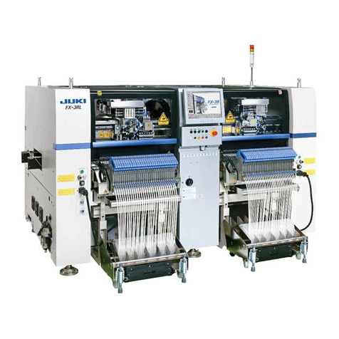
JUKI TR6SNR Operating manual

Matrix Tray Changer
TR6SNR/6SNX/6SNV
MAINTENANCE GUIDE
CUSTOMER SUPPORT DEPARTMENT

Important
(1) No part of this document may be copied or reproduced without the prior
permission of JUKI Corporation. (Including software and program)
(2) The contents of this document are subject to change without notice.
(3) This manual is prepared with extreme care. However, if you have any question
or find any error or omission in writing, contact our dealer or JUKI Corporation.
(4) JUKI Corporation shall disclaim all the responsibility for any trouble resulting
from the user's abnormal operation regardless of Item (3).

Maintenance Guide
Table of Contents
1
.
How to Set Up the System ................................................................. 1-1
1-1. Removing metal fixtures for transport...................................................................1-1
1-2. Confirmation of voltage specification....................................................................1-2
1-3. Mounting a shuttle unit .........................................................................................1-2
1-3. Mounting a shuttle unit .........................................................................................1-3
1-4. Leveling................................................................................................................1-4
1-5. Securing shuttle unit and mounter........................................................................1-5
1-6. Checking assembly position .................................................................................1-6
1-7. Connecting the FG cable (EN specifications only) ...............................................1-7
1-8. Mounting tray stacker ...........................................................................................1-8
2
.
Name of Covers and Detaching Covers ........................................... 2-1
2-1. Detaching covers..................................................................................................2-1
3
.
Replacement and Adjustment of Components
in Electrical Equipment Section ........................................................ 3-1
3-1. Layout diagram of electrical equipment section (standard) ..................................3-1
3-2. Layout diagram of electrical equipment section (CE-spec machine) ....................3-3
3-3. Replacement of circuit protector...........................................................................3-4
3-4. Replacement of AC servo driver...........................................................................3-5
3-5. Replacement of stepping motor driver..................................................................3-6
3-6. Replacement of power lamp.................................................................................3-7
3-7. Replacement of fan motor ....................................................................................3-8
3-8. Replacement of teaching spot..............................................................................3-9
3-9. Replacement of main PCB (TR6SNR) ...............................................................3-10
3-10. Replacement of main PCB (TR6SNX/6SNV) .....................................................3-15
3-11. Replacement of tray LED PCB
(option: run-out components indication switch).................................................3-18
3-12. Connector inserting positions of the main PCB (TR6SNR) ................................3-19
3-13. Connector inserting positions of the main PCB (TR6SNX/6SNV) ......................3-20
3-14. Connector inserting positions of the SCN PCB ..................................................3-21
4
.
Replacement and Adjustment of Sensors........................................ 4-1
4-1. Layout diagram of Z unit sensors .........................................................................4-1
4-2. Replacement and adjustment of Z-axis origin, minus limit sensor........................4-2
4-3. Replacement and adjustment of ZM plus limit detection sensor ..........................4-3
4-4. Replacement and adjustment of stacker set sensor.............................................4-4

Maintenance Guide
4-5. Replacement and adjustment of stacker lock sensor ...........................................4-5
4-6. Replacement and adjustment of shutter sensor ...................................................4-6
4-7. Layout diagram of Y unit sensor...........................................................................4-7
4-8. Replacement and adjustment of Y-axis origin,
minus limit and plus limit sensor .........................................................................4-8
4-9. Replacement and adjustment of chuck detection sensor .....................................4-9
4-10. Replacement and adjustment of tray pulled-out detection (+) switch .................4-10
4-11. Layout diagram or X unit sensor.........................................................................4-11
4-12. Replacement and adjustment of X-axis origin,
minus limit and plus limit sensor .......................................................................4-12
4-13. Replacement and adjustment of head ascent/descent sensor ...........................4-13
4-14. Layout diagram or shuttle unit sensor ................................................................4-14
4-15. Replacement and adjustment of shuttle origin,
minus limit and plus limit sensor .......................................................................4-15
4-16. Replacement and adjustment of pad size sensor and BGA sensor ...................4-16
4-17. Replacement and adjustment of cover lock sensor............................................4-17
4-18. Replacement and adjustment of cover interlock switch (standard).....................4-18
4-19. Replacement and adjustment of cover OPEN switch ASM (CE machine) .........4-19
4-20. Layout diagram of door sensors .........................................................................4-20
4-21. Replacement and adjustment of door lock detection sensor
and door open sensor.......................................................................................4-21
4-22. Replacement and adjustment of door sensors (CE machine) ............................4-22
4-23. Replacement and adjustment of transfer sensor ................................................4-23
4-24. Replacement and adjustment of wrong tray insertion sensor.............................4-24
4-25. Replacement and adjustment of inspection transfer stop sensor
(transfer inspection specification: optional).......................................................4-25
4-26. Replacement and adjustment of automatic width adjustment origin sensor
(automatic transfer width adjustment: optional) ................................................4-26
4-27. Replacement and Adjustment of the IS unit antenna (IS: Option) ......................4-27
5
.
Replacement and Adjustment of Motors.......................................... 5-1
5-1. Layout diagram of motors.....................................................................................5-1
5-2. Replacement of Z-axis motor ...............................................................................5-2
5-3. Replacement of X-axis motor ...............................................................................5-3
5-4. Replacement of Y-axis motor ...............................................................................5-4
5-5. Replacement of shuttle motor ..............................................................................5-5
5-6. Replacement of conveyor motor...........................................................................5-6
5-7. Replacement of automatic width adjustment motor
(optional: automatic width adjustment) ...............................................................5-7
Maintenance Guide
6
.
Replacement and Adjustment of Belts............................................. 6-1
6-1. Replacement and adjustment of X-axis belt (TR6SNR/TR6SNX) ........................6-1
6-2. Replacement and adjustment of Y-axis belt .........................................................6-2
6-3. Replacement and adjustment of shuttle belt (TR6SNR).......................................6-3
6-4. Replacement and adjustment of shuttle belt (TR6SER/TR6SNV)........................6-4
6-5. Replacement and adjustment of shuttle belt (TR6SNX) .......................................6-5
6-6. Replacement and adjustment of shuttle belt (TR6SXLX) .....................................6-6
6-7. Replacement and adjustment of transfer drive belt ..............................................6-7
6-8. Replacement and adjustment of transfer rail broadening/narrowing belt..............6-8
6-9. Replacement and adjustment of transfer belt.......................................................6-9
7
.
Replacement of Pneumatic Component........................................... 7-1
7-1. Layout diagram of pneumatic components in Y unit section ................................7-1
7-2. Replacement of tray chuck cylinder......................................................................7-2
7-3. Replacement of solenoid valves for shutter, tray chuck and shuttle .....................7-3
7-4. Replacement of solenoid valves for shutter and tray chuck speed reduction
(slow 2 mode: optional) ......................................................................................7-4
7-5. Layout diagram of pneumatic component in X unit section ..................................7-5
7-6. Replacement of head cylinder ..............................................................................7-6
7-7. Replacement of X-axis vacuum pad.....................................................................7-7
7-8. Replacement of X-axis solenoid valve..................................................................7-8
7-9. Replacement of X-axis ejector .............................................................................7-9
7-10. Replacement of shuttle ejector ...........................................................................7-10
7-11. Replacement of ejector filter element .................................................................7-11
7-12. Replacement of solenoid valves for decreasing head UP/DOWN speed
(slow 2 mode: option) .......................................................................................7-12
7-13. Layout diagram of pneumatic components in shuttle unit section ......................7-13
7-14. Replacement of BGA cylinder ............................................................................7-14
7-14-1. Adjustment of BGA cylinder speed controller ............................................................ 7-15
7-14-2. Adjustment of BGA cylinder speed controller (adjustment of exhaust air)................. 7-16
7-15. Replacement of shuttle movable pad packing....................................................7-17
7-16. Replacement of shuttle vacuum pad ..................................................................7-18
8
.
Air Piping Diagram ............................................................................. 8-1
8-1. List of air components ..........................................................................................8-1
8-2. Diagram of air piping (standard) ...........................................................................8-2
8-3. Air piping diagram (optional: slow 2 mode) ..........................................................8-3

Maintenance Guide
9
.
Test Mode............................................................................................ 9-1
9-1. Starting and finishing test mode ...........................................................................9-2
9-2. Initialization ..........................................................................................................9-3
9-3. Sensor check .......................................................................................................9-3
9-4. Head valve ...........................................................................................................9-4
9-5. Shuttle valve.........................................................................................................9-5
9-6. Head.....................................................................................................................9-5
9-7. BGA holder...........................................................................................................9-6
9-8. Y holder................................................................................................................9-7
9-9. Shutter..................................................................................................................9-8
9-10. Concentric nozzle.................................................................................................9-9
9-11. Z unit JOG............................................................................................................9-9
9-12. Speed selection..................................................................................................9-10
9-13. Teaching ............................................................................................................9-10
9-14. Inputting component count .................................................................................9-11
9-15. Complex movement ...........................................................................................9-13
9-16.X unit ..................................................................................................................9-14
9-17. Y unit ..................................................................................................................9-15
9-18. Z unit ..................................................................................................................9-16
9-19. Shuttle unit .........................................................................................................9-17
9-20. XY adjustment ....................................................................................................9-18
9-21. Conveyor adjustment (automatic width adjustment: optional) ............................9-21
9-22. Conveyor (automatic width adjustment: optional)...............................................9-22

Maintenance Guide
1-1
1
.
How to Set Up the System
1-1. Removing metal fixtures for transport
Remove the stopper that secures the X-axis carriage using the M4 hexagon socket head bolt
.
Then remove FIX BR that secures the head section using the M3 hexagon socket head bolt .
Note: It may happen that the head section is lowered if FIX BR is removed with no air
present inside. Be extremely aware of the risk that the head section should be
broken if you move the X-axis carriage by hand in the above situation.

Maintenance Guide
1-2
1-2. Confirmation of voltage specification
Confirm that your voltage meets the spec.
Check the rating nameplate attached to the lower right portion on the back of the equipment.
The value, on which a circle is put (for the label nameplate) or marking is put (for the aluminum
nameplate) in the “Volts” field, shows the set voltage specifications.
If your supplied voltage does not meet this condition, the voltage has to be changed.
Detach the E cover F , and a terminal block for changing the voltage will be exposed.
The voltage specification can be altered by changing the cable assembly of .
200
220
240
380
400
415
N.C
0
Volts 200 220 240 380 400 415
200に丸が付いている
場合は200V仕様
A circle on the
value of 200
means that 200V
is selected in the
specification.
According to the voltage specifications,
marking is put with a punch.

Maintenance Guide
1-3
1-3. Mounting a shuttle unit
Put the U-groove section of S base into the S base joint SH to the depth.
Mount the shuttle using four shuttle mounting screws .
Put the air tube and connector into the marker position as shown in the diagram.
S BASE U溝
CN0 05
CN0 39
CN0 40
CN0 42
BGAR
BGAL
PADR
PADL
VACL
VACR
S base U-groove

Maintenance Guide
1-4
1-4. Leveling
Place level vials on the conveyor rails and make level adjustment.
Secure accuracy of ±2 divisions or less on the level vial scale (use level vials having 1 Div = 0.05
mm/M).
Level vial

Maintenance Guide
1-5
1-5. Securing shuttle unit and mounter
After the height levels of the mounter and MTC, and the front and rear positions have been
adjusted, secure the shuttle unit, which enters the mounter, using the shuttle support parts shown
below.
Models needing this work: TR6SNX, and TR6SXLS
(This work is not necessary for TR6SNV.)
For the L specifications, remove the tie-up
bands from the cable fixing base inside the
GX-10, detach the fixing base, and then secure
it together with the S_BASE_PL again. (At
this time, replace the bolts that secure the
fixing base with the hexagon socket head cap
bolts (M4 ×10) supplied with the MTC.) After
the fixing base has been secured, secure the
cables with the tie-up bands.
For the L specifications, secure
to the screw holes in the upper
side. For the XL specifications,
secure to the screw holes in the
lower side.
(Note) Before detaching the MTC from the mounter main unit, be sure to
detach the shuttle support shown above.
Hexagon socket
head cap bolt
M4 ×10
S_BASE_BR
S_BASE_PL
Hexagon socket
head cap bolt
M4 ×10
Hexagon socket
head cap bolt
M4 ×6

Maintenance Guide
1-6
1-6. Checking assembly position
Once the system becomes ready for powering ON, confirm that the picking pad of shuttle and the
picking pad of X head are positioned on the same axis.
Boot the system in test mode, and after initialization, confirmation can be made by means of “H.P
Offset” of “19.XYZ ADJ” (see Section 10-19).
If the picking pad is displaced, adjustment is required.
< Displacement in Y-direction >
Loosen the mounting screws of S joint base A and S joint base B , and adjust the position.
< Displacement in X-direction >
Use “H.P Offset” in “19. XYZ ADJ” of test mode for adjustment.
Move X head with the arrow key, lower the head with the HEAD key, and make confirmation.
If the value of “H.P Offset” has been changed, then change the value of “Tray Ref” as well.
If displacement has been made in the a-direction using “H.P Offset”, displace “Tray Ref” in
a’-direction by the same degree.
If displacement has been made in b-direction using “H.P Offset”, displace “Tray Ref” in
b’-direction by the same degree.
If adjustment cannot be made by means of “H.P Offset”, use S dog PL for adjustment because
the stop position of shuttle can be changed if S dog PL is moved.
X方向
Y方向
a
b
a’
b’
トレイ基準位置
X-direction
Y-direction
Tray reference position

Maintenance Guide
1-7
1-7. Connecting the FG cable (EN specifications only)
For the machine with the EN specifications, connect the FG cable attached to the power cable to
the position shown in the Fig.
Power cable
insertion port
<MTC side>
Secure the FG cable to the M4
tap near the power cable
insertion port with the screw
supplied with the MTC.
FG cable
securing position
M4 tap
<Mounter side>
Remove the screw (1 location)
from the power cable insertion
port and tighten it together with
the FG cable.
Power cable
insertion port
FG cable securing position
M3 tap
Tighten the screw together
with the FG cable.

Maintenance Guide
1-8
1-8. Mounting tray stacker
Open the door and release the lock lever
.
Place the tray stacker on the stacker base and push it all the way in along the stacker
guide .
Push the parts A and B of the tray stacker to make sure that the tray stacker has been
put all the way in, and then lock the lock lever .
Close the door.
∗Note: When mounting the tray stacker with the air not supplied, check beforehand
that the shutter hook is closed in the direction indicated by .
If the tray stacker is forcibly mounted in the open status, this may cause the
shutter hook to break.
A
B

Maintenance Guide
2-1
2. Name ofCovers and Detaching Covers
2-1. Detaching covers
Top cover (40048880) Eleven screws (remove together with )
XF cover 6S (40048887) Six screws
X side cover (40048888) Seven screws
X cover (40048881) Six screws (remove after detaching )
(two screws are located inside X door.)
S cover EX (40049321) Three screws (mounted only for TR6SER)
S cover XL (40094981)Three screws (mounted only for TR6SXLX)
S_cover_10V (40118288) Three screws (mounted only for TR6SNV)
Y cover 6S (40048889) Four screws (two screws are located inside X cover.)
Valve cover (40048805) Two screws
C cover A6S (40049020) Ten screws (remove after detaching )
C cover B6S (40049021) Seven screws
E cover F (40048890) Six screws, 40098346 six retaining washers
X DOOR

Maintenance Guide
2-2
11
Side cover L (40048879) Twelve screws (remove after detaching )
12
Door 6S (40048891) Four screws
13
E cover L (40048879) Five screws
14
E cover R (40048892) Six screws
15
Side cover R (40048878) Eleven screws
DOOR COVER

Maintenance Guide
3-1
3
.
Replacement and Adjustment of Components in Electrical Equipment
Section
3-1. Layout diagram of electrical equipment section (standard)
No.
Part No.
Part name
Remarks
1
40040687
Z servo DRV ASM
2
40045704
Regenerative resistance
3
40045711
Stepping motor driver
X-axis
4
40045711
Stepping motor driver
Y-axis
5
40045711
Stepping motor driver
Shuttle
6
40045714
Noise filter
7
HB001420000
Power relay
8
HB001400000
Power relay
9
40045025
Surge absorber ASM

Maintenance Guide
3-2
No.
Part No.
Part name
Remarks
10
HX005500000
Switching power supply
11
40045016
AC fan motor ASM
12
40046217 note1
Main PCB A (6S) ASM
Spare part No.: 40095256 note3
For TR6SNR
40137757 note2
Main PCB A ASM (6S)
40095247 Main PCB ASM (6S)
Spare part No.: 40095246
For TR6SNX/6SNV
13
40042575
Slow mode CTRL PCB ASM
Slow 2 mode: optional
14
40042153
AWC PCB ASM
Automatic width adjustment: optional
note1. 40046217 is a part No. mounted in the ROM.
note2. 40137757 is a part No. not mounted in the ROM (Software is already written.)
note3. 40137756 can be used in common for TR6DNR/6SNR/5SNR.
Since software is already written in 40137756, ROM installation is not required.

Maintenance Guide
3-3
3-2. Layout diagram of electrical equipment section (CE-spec machine)
No.
Part No.
Part name
Remarks
1
HB001430000
Safety relay unit
2
HB001390000
Relay
3
E9641040000
Relay MY2, 24V DC

Maintenance Guide
3-4
3-3. Replacement of circuit protector
Remove the screw at “A” position, and the circuit protector can be pulled out toward you together
with the bracket.
Replace with the part of the same rating in the table below.
Name
Rating
Part No.
Description
CP1
3A
HA005240000
Main power supply
CP2
10A
HA00524000C
Servo driver
CP4
5A
HA00524000A
X-axis pulse driver
CP5
5A
HA00524000A
Y-axis pulse driver
CP6
5A
HA00524000A
Shuttle axis pulse driver
CP7
3A
HA005240000
Transfer motor
CP1
CP7CP6
CP5
CP4
CP2
This manual suits for next models
2
Table of contents
Other JUKI Industrial Equipment manuals

JUKI
JUKI EF08HD User manual

JUKI
JUKI KE-3010 Operating manual

JUKI
JUKI L-1A User manual

JUKI
JUKI LBH-1790AB User manual

JUKI
JUKI LK-1900B series Instruction Manual

JUKI
JUKI KE-1070 Operating manual

JUKI
JUKI PS-900-13090 User manual

JUKI
JUKI PS-800SB-8045 User manual

JUKI
JUKI AW-3S User manual

JUKI
JUKI KE-750 User manual