JUKI KE-2000 Series User manual

KE
KEKE
KE‑
‑‑
‑2010/2020/2030/2040
2010/2020/2030/20402010/2020/2030/2040
2010/2020/2030/2040
INST
INSTINST
INSTALLATION
ALLATIONALLATION
ALLATIONGUIDE
GUIDEGUIDE
GUIDE
JUKICORPORATION
JUKICORPORATIONJUKICORPORATION
JUKICORPORATION
ELECTRONICASSEMBLY&
ELECTRONICASSEMBLY&ELECTRONICASSEMBLY&
ELECTRONICASSEMBLY&
TESTSYSTEMSDIVISION
TESTSYSTEMSDIVISIONTESTSYSTEMSDIVISION
TESTSYSTEMSDIVISION
SMTTRAININGCENTER
SMTTRAININGCENTERSMTTRAININGCENTER
SMTTRAININGCENTER

(1)It is strictly prohibited to copy or reproduce part or all of the contents of this document
without our written approv07al (including software and programs).
(2)The contents of this document are subject to change without notice.
(3)This document has been prepared with our full commitment to perfection for users.
Should any ambiguity, error, missing and other defect be found, however, please contact
the dealer or the company.
(4)Note that we are not responsible for any result of improper operation or handling by the
customer regardless of the item (3) above.
(5)Windows is a registered trademark of Microsoft Corporation, US.
Other company names and product names contained in this document are registered
trademarks or brands of those companies.
Precautions

KE2000 Installation Manual
CONTENTS
1.Basic configuration and name of each part..........................................................................................1
1-1.KE-2010/2020/2040...........................................................................................................................1
1-2. KE-2030................................................................................................................................................2
2. Installing the main unit.............................................................................................................................3
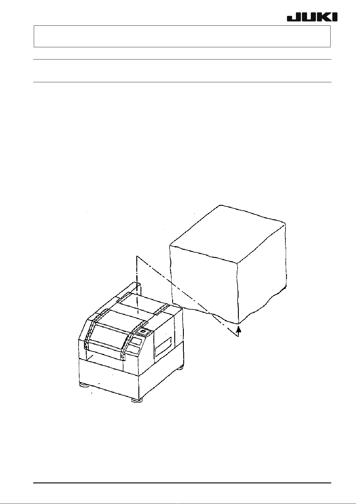
3. Detaching the packing materials from the machine................................................................................4
3-1. Overall machine cover .........................................................................................................................4
3-2. Safety cover..........................................................................................................................................5
3-3. Transport cover(only CE Machine) .................................................................................................. 6
3-4. Pneumatic units....................................................................................................................................6
3-5. Feeder relay cable 8 (For machines with fixed bank specification only)............................................. 7
3-6. Replacement table trolley ....................................................................................................................8
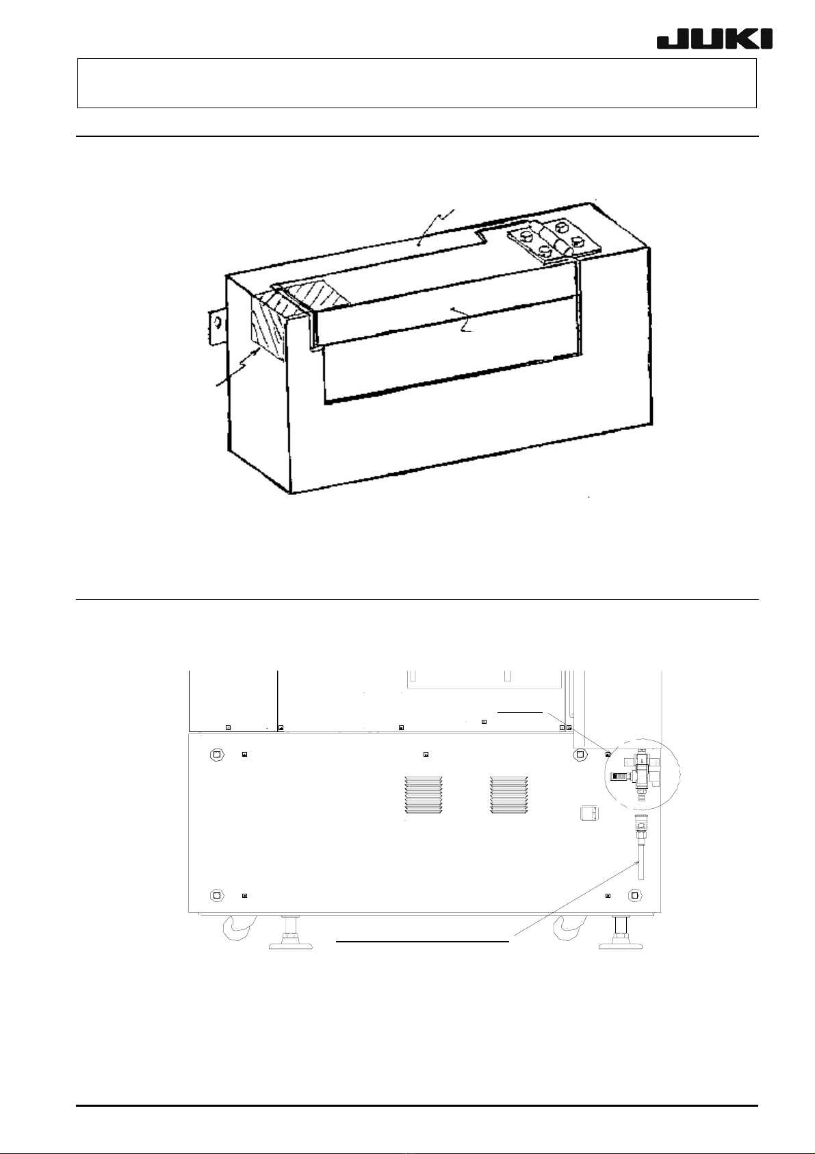
4. Adjusting the transport height and leveling the machine ......................................................................10
4-1. KE-2010/2020/2040 ...........................................................................................................................10
4-2. KE-2030..............................................................................................................................................13
5. X-Y unit...................................................................................................................................................15
5-1. Detaching the X-axis frame fixing parts (For model 2030 only)........................................................15
5-2. Detaching the head fixing parts .........................................................................................................16
6. Head unit................................................................................................................................................17
6-1. Detaching the packing materials........................................................................................................17
6-2. Detaching the head unit fixing parts ..................................................................................................18
7. Board transport unit ...............................................................................................................................20
7-1. Detaching the packing materials from the transport rail....................................................................20
7-2. Detaching the packing materials from the BU table..........................................................................20
7-3. Center station on the Y-axis drive side (For model 2030 only).......................................................21
7-4. Unpacking the supply parts................................................................................................................22
8. ATC unit..................................................................................................................................................23
9. CAL block...............................................................................................................................................23
10. Connecting the compressed air tube................................................................................................. 24
11. Connecting the power cord................................................................................................................ 26
11-1. 2010/2020/2040 ............................................................................................................................... 26
11-2. 2010/2020/2040 ............................................................................................................................... 28
11-2. 2010/2020/2040 ............................................................................................................................... 28
12. Mounting the accessories ..................................................................................................................30
12-1. Signal light........................................................................................................................................ 30
12-2. Vision monitor...................................................................................................................................30
12-3. Keyboard bracket.............................................................................................................................30

KE2000 Installation Manual
12-3. Keyboard bracket.............................................................................................................................31
12-4. HOD (Handheld operating device)...................................................................................................31
12-5. Hand knob........................................................................................................................................31
12-5. Hand knob........................................................................................................................................32
12-6. Feed relay cable...............................................................................................................................32
12-7. Chip box ...........................................................................................................................................33
13. Interface with external equipment......................................................................................................34
13-1. KE-2020/2040 ..................................................................................................................................34
13-2. KE-2010/2030 ..................................................................................................................................35
14. Connecting the matrix tray changer (MTC)........................................................................................39
14-1. Interface panel.................................................................................................................................. 39
14-2. TR-4SN.............................................................................................................................................40
14-3. TR-6SN and TR-6DN.....................................................................................................................40
14-3. TR-6SN and TR-6DN....................................................................................................................... 41
14-4. TR-5SN and TR-5DN....................................................................................................................... 42
15. Checking the machine before turning on the power..........................................................................43
16. Adjusting the height of the overall feeder exchange trolley(optional)............................................44
16-1. Caster plate mounting position ........................................................................................................44
16-2. Adding the trolley spacers (For height adjustment).........................................................................44
16-2. Adding the trolley spacers (For height adjustment).........................................................................45
16-3. Adjusting the bank stopper mounting position.................................................................................45
16-4. Adjusting the bank valve position ....................................................................................................46

KE2000 Installation Manual
1
1.
Basic configuration and name of each part
1-1. KE-2010/2020/2040
1-1-1. Standard Machine
Fig.1-1-1-1
Front view Fig.1-1-1-2
Right side view
1-1-2. CE Machine
Fig.1-1-2-1 Front view Fig.1-1-2-2
Right side view
(1)Vision monitor (5) Track ball
(2)LCD panel (6) Signal light
(3)HOD (Handheld Operating Device)unit(7)Mainswitch
(4)Keyboard (8) No-fuse circuit breaker

KE2000 Installation Manual
2
1-2. KE-2030
1-2-1. Standard Machine
Fig.1-2-1-1
Front view Fig.1-2-1-2
Right side view
1-2-2. CE Machine
Fig.1-2-2-1
Front view Fig.1-2-2-2
Right side view
(1) Vision monitor (5) Track ball
(2) LCD panel (6) Signal light
(3)HOD (Handheld OperatingDevice) unit (7)Mainswitch
(4) Keyboard (8) No-fuse circuit breaker

KE2000 Installation Manual
3
2. Installing the main unit
<Procedure>
1. Screw-in the adjusters to place the casters on the floor (ground) firmly before
transporting or moving the main unit.
2. Before moving the main unit using a forklift, be sure to put the fork under the main
unit from its front, and lift it up and move it after checking that the fork protrudes
sufficiently from the rear of the main unit.
<CAUTION>
1. When moving the main unit using a forklift, pay special attention to the load
center mark. (This caution also applies when using a pallet truck.)
2. Do not move the main unit using a forklift with the vision monitor and signal light
mounted. (This caution also applies when using a pallet truck.)
Signal light
Vision monitor
Load center mark
Caster
Adjuster

KE2000 Installation Manual
4
3. Detaching the packing materials from the machine
3-1. Overall machine cover
Detach the vinyl cover from the machine main unit. (This packing applies to only the
machines shipped to the domestic market.)
1) KE-2010, 2020, 2040
Dimensions of vinyl cover:1800 (W) x 1700 (D) x 1500 (H)
t 0.05 (Thickness)
2) KE-2030
Dimensions of vinyl cover:2600 (W) x 1500 (D) x 1500 (H)
t 0.05 (Thickness)
Note)The dimensions of both vinyl covers are determined based on the outside
dimensions of the machine applicable to the extra board size.
Fig 3-1-1

KE2000 Installation Manual
5
3-2. Safety cover
Peel off the filament tapes stuck on the safety cover.
Fig 3-2-1
Filament tapes Safety cover R
Safety cover F
Main unit

KE2000 Installation Manual
6
3-3. Transport cover (only CE Machine)
Peel off the filament tapes stuck on the transport cover.
Fig 3-3-1
3-4. Pneumatic units
Detach the air caps from the finger valve and drain bottle.
Fig 3-4-1 Left side view of KE-2030
Trans
p
ort cover
Filament ta
p
es
Trans
p
ort cover lid
Air ca
p
For factor
y
p
i
p
in
g
(
air tube
)

KE2000 Installation Manual
7
3-5. Feeder relay cable 8 (For machines with fixed bank specification only)
Peel off the filament tapes fixing the feeder relay tube and air tube.
Fig 3-5-1
※The front and rear of the connector bracket are secured to the cover FB and RBC,
respectively.
Filament ta
p
e
A
ir tube
Connector bracket
Lower portion
of main unit
Feeder rela
y
tube

KE2000 Installation Manual
8
3-6. Replacement table trolley
3-6-1. Overall replacement table trolley
Detach the air cap cover from the replacement table trolley.
Fig 3-6-1-1
3-6-2. Feeder relay cable
Peel off the filament tapes fixing the feeder relay tube and air tube.
Fig 3-6-2-1
Air cab Feeder bank
Overall Feede
r
Exchange trolley
Air tube
Connector rela
y
cable
Connector bracket
Trolley frame
(Overall Feede
r
Exchange
Filament

KE2000 Installation Manual
9
3-6-3. Trolley frame
Detach the P.P. band fixing the feeder bank and trolley frame.
Fig 3-6-3-1
Feeder bank
Overall Feede
r
Exchange
trolley (Floo
r
Trolley frame
P.P. band

KE2000 Installation Manual
10
4. Adjusting the transport height and leveling the machine
4-1. KE-2010/2020/2040
<Procedure>
1. Detach the cover FB, cover RBC, cover RBR, and cover RBL (Fig 4-1-1).
Detach the air cap put at the end of the rail (Fig 4-1-2,Fig 4-1-3).
※For only the model KE-2030, the rail is separated into four pieces, IN buffer, IN center
station, OUT center station, and OUT buffer.
Fig 4-1-1
Fig 4-1-2
Fig 4-1-3
Cover FB
Cover RBR
Cover RBC
Cover RBL

KE2000 Installation Manual
11
2. Loosen three hexagon
socket head bolts of each
adjuster.
(Make sure that the adjust
foot moves freely.)
3. When the adjusters are
raised from adjuster (1), (3),
(2), (4), (1), and so on in
that order, this ensures
relatively smooth raising of
the machine level.
4. Level the machine in the
back and forth direction.
Put a level vial in the state
shown by dotted lines and
move the vertically adjusters
(1)・(2)、(3)・(4) in that order
so that the scale on the level
vial shows the set value stated in the level setting table (supplied with the machine) ±1.
The transport height is adjusted to 900 mm for domestic models and 950 mm for
overseas models.
5.Next, level the machine in the
horizontal direction. Put a level
vial in the state shown by
continuous lines and vertically
move the adjusters (1)・(4)、(2)・
(3) in that order so that the scale
on the level vial shows the set
value stated in the level setting
table (supplied with the machine)
±1.
6.Repeat above steps 4 and 5 to
level the machine so that the level
on the base bar B enters the
standard range.
(The scale of the level vial to be used
for this adjustment is 0.05/div.)
Fig 4-1-4
Viewed from the bottom
Viewed from the top
Fig 4-1-5
Base bar B
Base bar R
Base bar FLevel vial

KE2000 Installation Manual
12
7. Lock the adjust nuts. With the adjust nuts locked, check again that the scale on the
level vial shows the set value ±1.
8. Tighten three hexagon socket head bolts of each adjuster.
<CAUTION>
If the unit may move due to the vibration during operation, attach the M8 X 30
hexagonal hole bolts B (3) and the M8 nuts C (3) packed with the unit. Tighten the
bolt B by hand. After the tip of the bolt touches the floor, turn it clockwise by 15
degrees with a wrench, then fix it by the nut C. In closing, make sure that the unit is
level. It is not recommended to place a rubber sheet on the floor.
Fig 4-1-6
Adjust nuts
Adjust foot
Hexa
g
on socket head bolt

KE2000 Installation Manual
13
4-2. KE-2030
<Procedure>
1. Detach the cover FBR, cover FBL, cover RBR30, cover RBCR30, cover RBCL30, and
cover RBL30.
2. Loosen three bolts A(see the fig 4-2-5) fixing the adjust bolt and adjust foot of each
adjuster. (Make sure that the adjust foot moves freely.)
Fig 4-2-1
Cover FBR Cover FBL
Cover FBR30 Cover RBCL30
Cover RBCR30 Cover FBL30
Fig 4-2-2
Viewed from the bottom
marks indicate the ad
j
uster
p
ositions.

KE2000 Installation Manual
14
3. Adjust the adjusters (1), (3), (4), and (6) to level the machine in the back and forth, and
horizontal directions(see the fig 4-2-2). At this time, a level vial is placed on the
hatching on the top of the base frame(see the fig 4-2-3). (A level vial is placed on the
transport base unit only for EXTRA machines.)
4. Place the adjusters (2) and (5) on the floor and level the machine so that the scale on
the level vial shows the set value stated in the setting table ±1. The tra-nsport height
is adjusted to 900 mm for domestic models and 950 mm for overseas models.
5. Lock the adjust nuts. Level the machine so that the scale on the level vial shows the
set value stated in the setting table ±1.
6. Tighten three bolts A fixing the adjust bolt and adjust foot of each adjuster.
<CAUTION>
If the unit may move due to the
vibration during operation, attach the
M8 X 30 hexagonal hole bolts B (3)
and the M8 nuts C (3) packed with the
unit. Tighten the bolt B by hand. After
the tip of the bolt touches the floor,
turn it clockwise by 15 degrees with a
wrench, then fix it by the nut C. In
closing, make sure that the unit is
level. It is not recommended to place
a rubber sheet on the floor.
Fi
g
4-2-3
Fig 4-2-4
Viewed from the top
Transport base unit(EXTRA)
Transport base
unit(EXTRA)
A
d
j
ust foot
A
d
j
ust nuts
Hexa
g
on socket head bolt

KE2000 Installation Manual
15
5. X-Y unit
5-1. Detaching the X-axis frame fixing parts (For model 2030 only)
Detach the stopper rubber fixing the X-axis frame and set-up caution tag.
set-up caution tag
WARNING
WARNINGWARNING
WARNING
To prevent the body from injury which can be caused by
accidental activation of the machine , cut off the power to
the machine before starting to work.
Fig 5-1-1

KE2000 Installation Manual
16
5-2. Detaching the head fixing parts
Detach the stopper rubber fixing the head and set-up caution tag.
set-up caution tag
WARNING
WARNINGWARNING
WARNING
To prevent the body from injury which can be caused by
accidental activation of the machine , cut off the power to
the machine before starting to work.
※Caution for packing
<Fix the stopper rubber>
●KE-2010/2020/2040⇒Move the L-Head completely to the left of the X-axis frame.
●KE-2030 ⇒Move the L-Head completely to the left of the X-axis frame and R-Head
completely to the right of the X-axis frame.
Fig 5-2-1
This manual suits for next models
4
Table of contents
Other JUKI Industrial Equipment manuals

JUKI
JUKI PS-800SB-8045 User manual

JUKI
JUKI LK-1900B series Instruction Manual

JUKI
JUKI KE-750 User manual

JUKI
JUKI 72005824 User manual

JUKI
JUKI KE-2050 Operating manual

JUKI
JUKI L-1A User manual

JUKI
JUKI AF05 User manual

JUKI
JUKI AMS-221F User manual

JUKI
JUKI FX-3R Operating manual

JUKI
JUKI KE-3010 Operating manual
Popular Industrial Equipment manuals by other brands

Siemens
Siemens SIRIUS 3RT2.1 Series Original operating instructions

PMC
PMC PHX-2 Service manual

WBM
WBM XPC500 Grapple Parts, Service and Installation

Greenheck
Greenheck OPA Installation, operation and maintenance manual

Balluff
Balluff BOS R254K-UUI-LH12-S4 installation guide

Unitary products group
Unitary products group DGAD installation manual