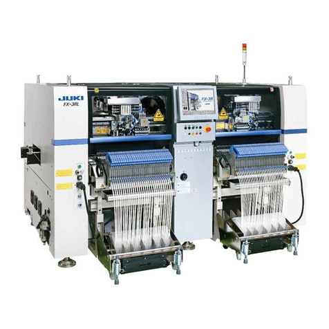
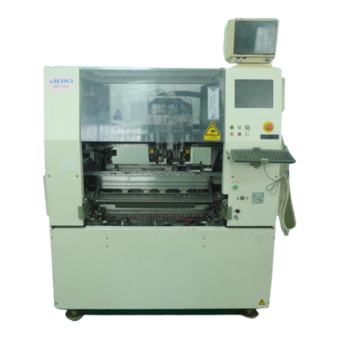
JUKI RS-1 User manual

Fast Smart Modular Mounter
RS-1/RS-1XL/RS-1R
PACKING GUIDE

Important
(1) No part of this document may be copied or reproduced without the prior
permission of JUKI Corporation. (Including software and program)
(2) The contents of this document are subject to change without notice.
(3) This manual is prepared with extreme care. However, if you have any question
or find any error or omission in writing, contact our dealer or JUKI Corporation.
(4) JUKI Corporation shall disclaim all the responsibility for any trouble resulting
from the user's abnormal operation regardless of Item (3).
(5) Microsoft, Windows are registered trademarks or trademarks of Microsoft
Corporation in the United States and /or other countries.
The company names and product names mentioned in this document are
generally registered trademarks or trademarks of the respective companies.

Packing Guide
Table of Contents
Chapter 1 Head Unit ··············································································· 1-1
1-1 Securing the Head Unit Fixing Parts ··························································· 1-1
1-1-1 Securing the LNC Z-Axis Fixing Parts ················································· 1-1
1-1-2 Securing the ZA-Axis ······································································ 1-2
1-2 Attaching the Packing Materials ································································· 1-3
1-3 Securing the Head Unit Fixing Parts (Head Rev. A and Later)··························· 1-4
1-3-1 Securing the LNC Z-Axis Fixing Parts ················································· 1-4
1-3-2 Securing the ZA-Axis ······································································ 1-5
1-4 Attaching the Packing Material (Head Rev. A and Later) ·································· 1-5
Chapter 2 X-Y Unit·················································································· 2-1
2-1 Securing the X-Axis Frame······································································· 2-1
2-2 Securing the Head·················································································· 2-2
Chapter 3 Board Transport Unit ······························································· 3-1
3-1 Packing the Accessory Units ····································································· 3-1
3-2 Packing Procedure ················································································· 3-2
3-2-1 Center Part··················································································· 3-2
3-2-2 Left and Right End Parts·································································· 3-2
Chapter 4 Base Bridge Section································································ 4-1
4-1 ATC Unit······························································································· 4-1
4-2 General View of Base Bridge (ATC and VCS Light Units) ································ 4-2
Chapter 5 Signal Light ············································································ 5-1
Chapter 6 Safety Cover ··········································································· 6-1
Chapter 7 Pneumatic Units······································································ 7-1
Chapter 8 Electric Fixed Bank ································································· 8-1
8-1 Detaching the Packing Parts ····································································· 8-1
8-2 Packing Procedures················································································ 8-1
Chapter 9 LCD Monitor ··········································································· 9-1
Chapter 10 Overall Machine Cover ························································· 10-1
Chapter 11 Packing the Accessory Units ················································ 11-1
11-1 Outer Carton Case ··············································································· 11-1
11-2 Check List for Units and Components to Be Put in the Carton Box ·················· 11-2
Chapter 12 Transport Extension (Option)················································ 12-1
Chapter 13 Other Optional Units ···························································· 13-1
Chapter 14 Feeder Exchange Trolley······················································ 14-1
Chapter 15 Tape Set Unit (Machine Rev. D and Later) ······························ 15-1
Chapter 16 Touch Pen (RS-1R Only)······················································· 16-1
Packing Guide
1-1
DANGER
To prevent the body from injury which can be caused by
accidental activation of the machine, cut off the power to the
machine before starting to work.
Chapter 1 Head Unit
1-1 Securing the Head Unit Fixing Parts
1-1-1 Securing the LNC Z-Axis Fixing Parts
1) Affix the limit damper to the ZM stopper as shown in the Fig. below.
* Affix the ZM rubber after degreasing the ZM stopper.
2) Make sure that the Z-axis is located at its uppermost position. Attach the stopper to
the tap of the Z-motor (portion shown in the Fig. below) and secure it so that the
limit damper is in contact with the belt.
(Secure the CAUTION tag at one location of the metal fixture on the right.)
3) Make sure that the Z slide bracket is secured firmly in the vertical direction.
Mounting position of LNC Z-axis fixing parts
Securing of LNC head Z-axis fixing parts
40046528 ZM stopper
40046644 ZM rubber (*)
ZM stopper
SL6030892TN
M3
×
8 SEMS cap bolt

Packing Guide
1-2
1-1-2 Securing the ZA-Axis
1) Fix it with 40182877 ZA_FIXED_BRACKET as shown.
There are 4 screws. SL6051092TN.
2) Attach the Caution tag to the bracket.

Packing Guide
1-3
1-2 Attaching the Packing Materials
Cover the lower portion of the head with the rust preventive paper sheet (Oji Paper Co., Ltd.
KS-VC1 Ferror-bright u-35ss-1 (for plastic)) and put desiccating agent around a part between
the OCC camera unit and light unit.
Caution tag (Yellow)
40087186
Desiccating
agent
Rust preventive
paper

Packing Guide
1-4
1-3 Securing the Head Unit Fixing Parts (Head Rev. A and Later)
1-3-1 Securing the LNC Z-Axis Fixing Parts
1) Assemble the COVER_CUSHION (40049671) to the ZM_STOPPER (40210361) using
SM4030601SC.
* For the ZM stopper, assemble the rubbers to different surfaces. Therefore, two rubbers are
used for one machine.
2) Face the rubber toward the front and slightly insert the stopper in the direction shown in the Fig.
When the stopper is in contact with the motor, move the Z-axis up and down to check that it
does not move, and then secure it temporarily using SL6030892TN (4 pcs.).
* Do not push excessively. Doing so may cause component breakage.
3) Check that the Z-axis does not move in the vertical direction and that it is secured, and then
tighten SL6030892TN (4 pcs.) firmly. After that, attach the caution tag to each of the left and
right.
40210361 ZM_STOPPER ×2 pcs.
40049671 COVER_CUSHION ×8 pcs.
SM4030601SC ×8 pcs.
SL6030892TN ×4
pcs.

Packing Guide
1-5
1-3-2 Securing the ZA-Axis
It should be performed as in 1-1-2.
1-4 Attaching the Packing Material (Head Rev. A and Later)
It should be performed as in 1-1-2.
Front view
Caution tag (yellow)
Part No. 40087186 should
be used.
Caution tag (yellow)
Part No. 40087186 should
be used.

Packing Guide
2-1
Chapter 2 X-Y Unit
2-1 Securing the X-Axis Frame
1) Put the X_FRAME_END assembly tightly in contact with the Y-stopper assembly and
secure the Y_FIX_BR_3020 to the X_FRAME_END assembly and Y_MOTOR_FRAME
with the screws, and then secure them to the X-axis frame.
After securing, check to make sure that the Y stopper assembly and the X-axis frame end
assembly are in intimate contact with each other.
2) Attach the set-up caution tag (yellow, part No.: 40087186) to the Y_FIX_BR_V2
※左右のXフレームエンドともに、実施して下さい。
Y_FIX_BR_V2 (40106051)
X_FRAME_END ASM
Caution tag
Caution tag
BASE_FRAME ASM
BASE_FRAME ASM
SCREW (SL6061292TN) (8)
Y_STOPPER ASM
Y_STOPPER ASM

Packing Guide
2-2
2-2 Securing the Head
1) Attach the set-up caution tag (yellow, part No.: 40087186) to the screw mounting
oval hole part of the X_FIX_BR.
2) Move the head to the leftmost position when viewed from the rear and push it against the
X-stopper rubber.
3) Keep this status and secure the HEAD_TOP_BASE and X-axis frame with the
X_FIX_BR.
Adhere the stopper rubber to the X_FIX_BR and secure the components while pushing
the stopper rubber against the HEAD_TOP_BASE.
Degrease the adhesion surface of the rubber with alcohol.
X STOPPER PLATE (L132E821000) SCREW (SL6061292TN) (2)
X STOPPER PLATE,
surface of the stopper
rubber

Packing Guide
3-1
Chapter 3 Board Transport Unit
3-1 Packing the Accessory Units
Put the parts used for packaging in the cardboard box 40077701 together with the other supplied
parts.
(See the packing instructions for accessories.)
Remove the following two units from the transport unit and pack them.
<Accessory units>
Number of accessory support pins
•40128431 Support pin assembly:12 pcs. (20 pcs. for XL)
Fig. 3-1-1 Support pin assembly

Packing Guide
3-2
3-2 Packing Procedure
3-2-1 Center Part
1) When the width of the transport rail is set to the minimum board width (30 mm),
put a polyethylene pad at the center part and fix it.
2) Set the width of the transport rail to the minimum level (30 mm) and attach a filament tape
to the rail plate above the screw shaft (two locations).
3-2-2 Left and Right End Parts
1) Put a polyethylene pad in the part projected from the main unit.
2) Cover the left and right end parts with an air cap sheet and secure them with a filament tape
CAUTION
•
Pay special attention so that no load is applied to the rail
plate (black portion).
•
If the rail plate is bent, the machine cannot be operated.
Rail plate R
Filament tape
Rail plate F
* Care should be taken so that the air
cap roll is not in contact with any
sensors.
Filament tape
Put a polyethylene pad and fix it.
(Polyethylene pad PP45)
Fix the support table firmly with filament tapes so
that any vertical play is not produced.

Packing Guide
4-1
Chapter 4 Base Bridge Section
4-1 ATC Unit
1) Secure the slide plate with a bundled wire band.
2) Attach the caution tag (yellow, 40087186).
Fig. 4-1-1 ATC unit

Packing Guide
4-2
4-2 General View of Base Bridge (ATC and VCS Light Units)
1) Cover the entire base bridge with rust preventive paper and secure the rust preventive paper
with filament tapes.
2) Cover the whole with rust preventive paper and fix with filament tape
Air cap
Rust preventive paper

Packing Guide
5-1
Chapter 5 Signal Light
1) Push the slide at the root of the signal light to lay it down toward the rear of the machine.
2) Wind the packing material on the light portion and secure it to the main unit with a filament
tape.
Slide.
Rear side
Wind the packing material on the light portion and
secure it to the main unit with a filament tape.

Packing Guide
6-1
Chapter 6 Safety Cover
As shown in the Fig. below, fix the safety covers with a filament tape so that they are not
opened.
Front
Rear

Packing Guide
6-2
* Be sure to pack the side covers of the open/close section with air caps and filament tapes so
that they can be protected from the safety cover.
* Paste the filament tape on the contact surface of safety cover stopper rubber and the
main body cover, and pack the safety cover.
Finally wrap with the wrapping material and fix the safety cover so that it does not move.
Front
Rear
Front
Rear

Packing Guide
7-1
Chapter 7 Pneumatic Units
1) Protect the finger valve with an air cap sheet.
(Put the finger valve and screws in the carton box when packing the steel portions.)
2) Detach the air combination from the main unit, wrap it with an air cap sheet, and put it in the
carton case. (Styrofoam packing)
For the domestic transportation, wrap the main unit with the air combination installed.
Cover the top end of the air tube with a vinyl bag.
3) Store the drain set assembly in the carton box as packing accessories.
40093785 ASM_DRAIN_TANK
Part No. Part name Q’ty Remarks
40016815
DRAIN TANK
1
Packing accessory
40016814
DRAIN TANK STAY
1
Packing accessory
40093721
DT_STAY_BR
1
Assembled into the
main unit
SL6040892TN
SCREW M4 L=8
4
2 pcs.: Packing, 2
pcs.: Main unit
* Packing accessories are listed in "11-2 Check List for Units and Components to Be Put in
the Carton Box".
For the overseas transportation, detach the air
combination from the main unit
Cover the top end of the air tube with a vinyl
bag.

Packing Guide
8-1
Chapter 8 Electric Fixed Bank
This work is performed only for the electric fixed bank specifications.
8-1 Detaching the Packing Parts
Detach the units and parts assembled to the machine main unit. Each assembly screw is packed
with the relevant part.
8-2 Packing Procedures
①Please fix the tape holder of the fixed bank specification with filament tape while covering with
the air cap while assembling it to the main body.
Reel holder assembly
Trash box
Fig. 8-1-1

Packing Guide
8-2
②In case of “fixed bank specification”, pack the reel holder as shown below.
○Reel holder assembly
Roll the air cap onto the reel holder and fix it with filament tape.
Refer to chapter 14 feeder exchange trolley reel holder
packaging method
○Trash box
Pack the 39 separation plates with air cap and
paste them with filament tape to the trash box.
Fig. 8-2-1
With the trash box set in the reel holder assembly, pack it in the packing box
(40080703: CARTON_CASE_LL_PRINTING_DRAWING). (Add air cushion for
clearance.)
Other manuals for RS-1
1
This manual suits for next models
2
Table of contents
Other JUKI Industrial Equipment manuals

JUKI
JUKI 72005824 User manual

JUKI
JUKI KE-2000 Series User manual

JUKI
JUKI FX-3R Operating manual

JUKI
JUKI AMS-221F User manual

JUKI
JUKI TR6SNR Operating manual

JUKI
JUKI M92 Manual

JUKI
JUKI LBH-1790AB User manual

JUKI
JUKI TL-2020 PE User manual

JUKI
JUKI ACF-164-1903 Quick start guide

JUKI
JUKI MEB-3200C User manual
Popular Industrial Equipment manuals by other brands

HEIDENHAIN
HEIDENHAIN ERN 1323 Mounting instructions

ABB
ABB GridShield 3P Installation, operation and maintenance manual

PennBarry
PennBarry Domex Operation & maintenance manual

Pfannenberg
Pfannenberg PWS 7032-24V Series operating manual

Skov
Skov DOL 100 Technical user guide

Siemens
Siemens 5SV8101-6KK operating instructions