JUKI KE-2070 User manual

High-Speed Flexible Mounter
KE-2070/KE-2080
MS PARAMETER
JUKICORPORATION
SMTCENTER CUSTOMERSERVICEDEPT.
ELECTRONICASSEMBLY& TESTSYSTEMSDIV.

(1) This manual or software may not be copied or reproduced (duplicated), in whole or part,
without the express prior written consent of JUKI Corp.
(2) This manual is subject to change without notice.
(3) This manual is written as carefully as possible. However, if you have a question,
or find a mistake or missing information, contact our dealers or JUKI Corp.
(4) JUKI Corp. is not responsible for any defects or malfunction due to your abnormal
operation.
(5) Windows is a registered trademark of Microsoft Corporation, US.
Other company names and product names contained in this document are registered
trademarks or brands of those companies.
Im
p
ortant

KE-2070/2080 MS Parameter
CAUTION
Never operate this machinewith voltage specifications other than those specified.
Before turning ON the power, make sure that the machine is in the safe status.
Before turning ON the power, make sure that no work personnel exist inside the
machine.
Before turning ON the power, make sure that no objects (such as adjustment
tools) hindering any operationinside the machine aremounted or placed.
Before supplying the air, always turn OFF the power completely.
CAUTION
To prevent any personal injury, do not put your hand inside the machine, or your
face or head close to the machine during HOD operation.
i Rev. 1.00

KE-2070/2080 MS Parameter
[1] Overview..................................................................................................1-1
1-1. Definition ..................................................................................................................1-1
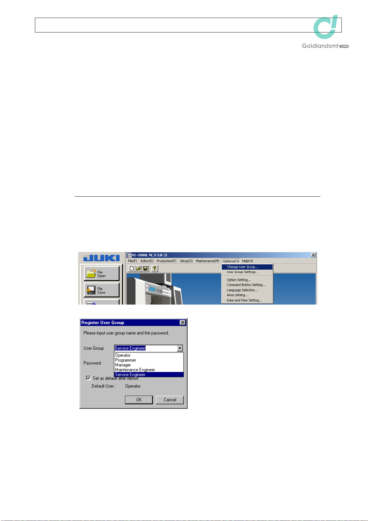
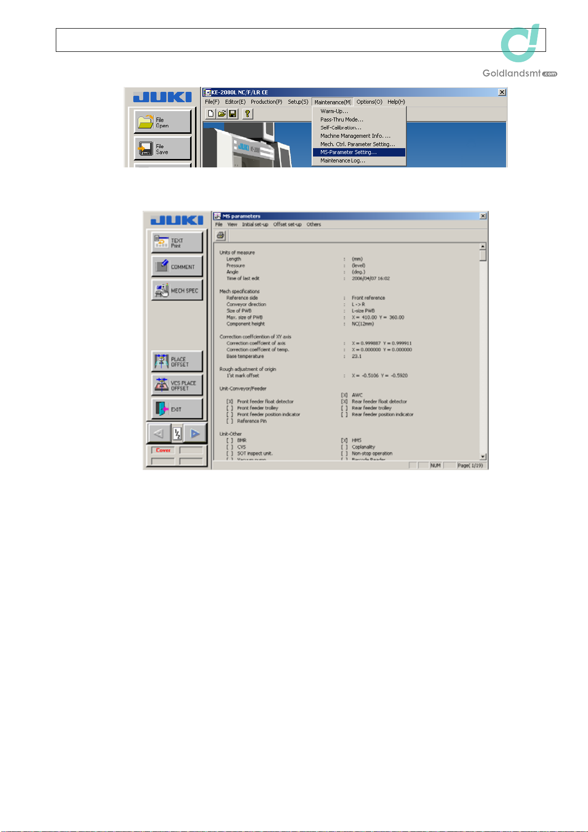
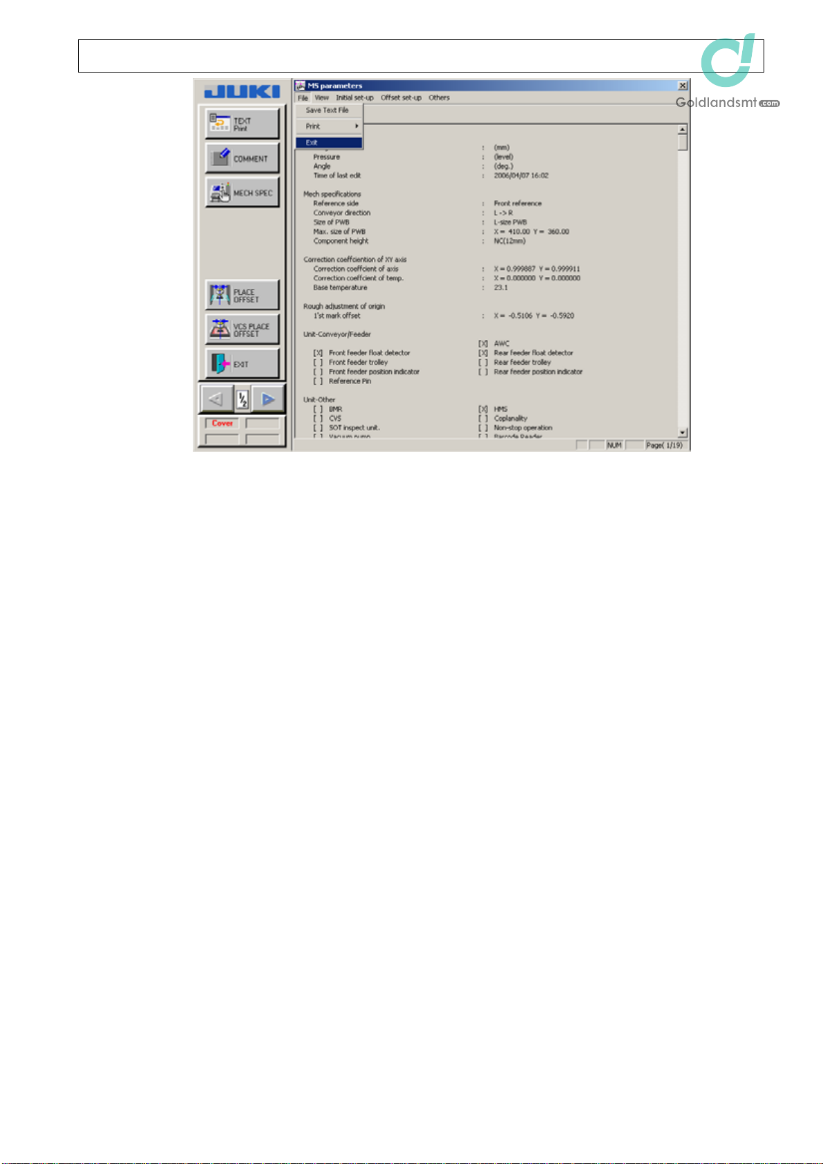
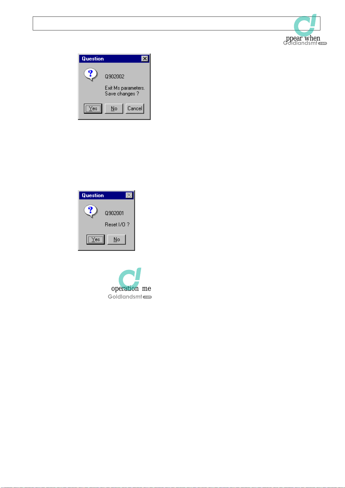
1-2. Starting up and exiting the MS parameter ................................................................1-1
1-3. Configuration............................................................................................................1-4
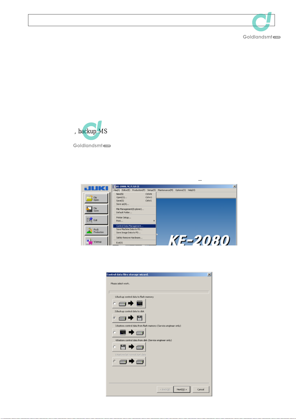
1-4. MS parameter storage locations...............................................................................1-5
1-5. Basic operation.......................................................................................................1-14
[2] Control menu ...........................................................................................2-1
2-1. Start up.....................................................................................................................2-1
2-2. Menu contents..........................................................................................................2-1
2-3. XY move...................................................................................................................2-2
2-4. Z move .....................................................................................................................2-3
2-5. Conveyor control ......................................................................................................2-4
2-6. Light map .................................................................................................................2-4
2-7. Light setting..............................................................................................................2-5
2-8. Nozzle up cylinder ....................................................................................................2-5
[3] Initial set-up..............................................................................................3-1
3-1. Machine specifications .............................................................................................3-1
3-2 Square adjustment ...................................................................................................3-2
3-3. Origin rough adjustment ...........................................................................................3-5
3-4. XY axis correction coefficient ...................................................................................3-6
3-5. Options.....................................................................................................................3-7
3-6. Action specifications.................................................................................................3-9
3-7. X axis curve correction ...........................................................................................3-14
3-8. Comment................................................................................................................3-15
[4] Offset set-up ............................................................................................4-1
4-1. Laser/Sensor Offset .................................................................................................4-1
4-2. OCC offset................................................................................................................4-8
4-3. CAL block offset .....................................................................................................4-17
4-4. Head offset .............................................................................................................4-19
4-5. VCS offset ..............................................................................................................4-26
4-6. Coplanarity offset ...................................................................................................4-42
4-7. ATC offset...............................................................................................................4-45
4-8. CVS offset ..............................................................................................................4-49
4-9. Conveyor offset ......................................................................................................4-51
4-10. Pick-up reference position offset ............................................................................4-54
4-11. General placement offset .......................................................................................4-56
4-12. θ-axis offset ............................................................................................................4-60
4-13. PLCC offset ............................................................................................................4-61
4-14. SOT inspect unit offset ...........................................................................................4-62
4-15. VAC-CAL offset ......................................................................................................4-64
ii Rev. 1.00

KE-2070/2080 MS Parameter
4-16. Head parking position.............................................................................................4-65
4-17. Bank correction ......................................................................................................4-66
4-18. Vacuum calibration .................................................................................................4-67
[5] Upgrade ...................................................................................................5-1
5-1. VCS..........................................................................................................................5-1
5-2. I/O ............................................................................................................................5-2
5-3. B/F............................................................................................................................5-3
5-4. LNC60 ......................................................................................................................5-4
5-5. Servo Amp................................................................................................................5-5
[6] Delete software ........................................................................................6-1
6-1. I/O ............................................................................................................................6-1
6-2. B/F............................................................................................................................6-2
6-3. JVS...........................................................................................................................6-3
[7] Others ......................................................................................................7-1
7-1. CAL piece holder......................................................................................................7-1
7-2. Editing the BOC mark position .................................................................................7-1
7-3 FCS jig component pick position ..............................................................................7-2
iii Rev. 1.00

KE-2070/2080 MS Parameter
[1] Overview
1-1. Definition
MS parameters record the assembling status of the machine and are used as references for
operation.
Basically, the MS parameters are classified into three groups, "Initial set-up" that records
whether or not optional units are used and the action (motion) specifications, "Offset set-up"
that records errors to the design values during assembly, and "Upgrade" that upgrades the
operation software after replacement of the control board and records it.
Example of "Offset set-up"
Example: Head assembling position (in case of left end (L1) head of KE2070)
Assembling position (51.8877) = Design value (51.5) + MS parameter (0.3877)
1-2. Starting up and exiting the MS parameter
cChange the user group to "Service Engineer".
1-1 Rev. 1.00

KE-2070/2080 MS Parameter
dSelect [MS-Parameter Setting] from the [Maintenance] menu.
eThe MS parameter initial screen will appear.
fTo exit the MS parameter, click the [X] mark at the upper right corner of the MS
parameter initial screen.
Or, select [Exit] from the [File] menu or click the [Exit] command button at the
lower left portion of the screen.
1-2 Rev. 1.00

KE-2070/2080 MS Parameter
1-3 Rev. 1.00

KE-2070/2080 MS Parameter
gIf you have changed any MS parameter, the following message will appear when
exiting the MS parameter.
To save the MS parameter values, click [Yes]. To keep the previous values before
running the MS parameter, click [No]. To continue the MS parameter, click
[Cancel].
hSubsequently, the message prompting you to reset I/O will appear. Normally, click
[Yes] unless an interference with other unit is predicted as the head is moved
smoothly.
1-3. Configuration
The MS parameter operation menu is classified into three groups, Initial set-up, Offset
set-up, and Others.
• Initial set-up: This setup is used when installing the machine. For details, see Chapter 3.
• Offset set-up: This setup is used when replacing a mechanical part. For details, see
Chapter 4.
• Others: This setup is used to copy the operation program to each board when
replacing the BASE-FEEDER board, I/O CPU board, or IPX-3 board.
For details, see Chapter 5.
If you press the right mouse button or F9 key, the Control menu will appear. For details, see
Chapter 2.
1-4 Rev. 1.00

KE-2070/2080 MS Parameter
1-4. MS parameter storage locations
The MS parameter is saved in the "D:¥Juki¥Data" folder.
The following shows the file names and functions (Sample for KE-2070).
CTL2070S.DAT Mechanical control parameters
DSN2070S.DAT Design dimensions, such as nozzle length and height
MPD2070S.DAT Design coordinate values related to mechanical units of the machine
MSP2070S.DAT MS parameters
OPT2070S.DAT Information on optional units and optional operations
POS2070S.DAT Assembly dimensions related to mechanical units of the machine
SUP2070S.DAT Machine setup information
Additionally, backup MS parameters are saved into FLASH ROM on the BASE-FEEDER
board.
To save the MS parameters, follow the steps below to create a backup file on a floppy disk.
1-4-1 Saving the control data into a backup file
cSelect [Control Data Management...] from the [File [F]] menu.
dThe Control data files storage wizard will appear. In this window, check on [2.
Backup control data to disk] and click [Next].
1-5 Rev. 1.00

KE-2070/2080 MS Parameter
eSelect the save destination, and then click [Next].
fCheck the contents to be saved and
the save destination, and then click
[Next].
gSelect [Action].
1-6 Rev. 1.00

KE-2070/2080 MS Parameter
hThe progress status is displayed. When the backup is completed, the following
screen will appear. Select [Finish].
iThe following file has been created.
1-7 Rev. 1.00

KE-2070/2080 MS Parameter
1-4-2 Restoring the control data from a backup file
To restore a backup file, follow the steps below.
cSelect [Control Data Management...] from the [File [F]] menu.
dThe Control data files storage wizard will appear. In this window, check on [4.
Restore control data from disk] and click [Next (N)].
eCheck that the restore source is set at
[Floppy disk [F]] and click [Next].
1-8 Rev. 1.00

KE-2070/2080 MS Parameter
fSelect a desired file in [Restoring origin], check that the device set in [Restoration
end] is correct, and then click [Next].
gSelect [Action].
hThe progress status is displayed.
When the backup file is restored
completely, the following screen
will appear. Select [Finish].
1-9 Rev. 1.00

KE-2070/2080 MS Parameter
1-4-3 Saving the control data into a flash memory
cSelect [Control Data Management...] from the [File [F]] menu.
dThe Control data files storage wizard will appear. In this window, check on [1.
Backup control data to flash memory] and click [Next].
eCheck the contents to be saved and
the save destination, and then click
[Next].
1-10 Rev. 1.00

KE-2070/2080 MS Parameter
fSelect [Action].
gThe progress status is displayed. When the backup is completed, the following
screen will appear. Select [Finish].
1-11 Rev. 1.00

KE-2070/2080 MS Parameter
1-4-4 Restoring the control data from a flash memory
To restore a backup file, follow the steps below.
cSelect [Control Data Management...] from the [File [F]] menu.
dThe Control data files storage wizard will appear. In this window, check on [3.
Restore control data from flash memory] and click [Next (N)].
1-12
eSelect a desired file in [Restoring
origin], check that the device set in
[Restoration end] is correct, and
then click [Next (N)].
Rev. 1.00

KE-2070/2080 MS Parameter
fSelect [Action].
gThe progress status is displayed. When the backup is completed, the following
screen will appear. Select [Finish].
1-13 Rev. 1.00

KE-2070/2080 MS Parameter
1-5. Basic operation
1-5-1. Updating the data
When obtaining each data, the newly set (changed) data will become valid when selecting
[OK] to complete the data setup.
The offset coordinate values become valid after the home position return has been
completed.
Therefore, when only data is changed, this change is not valid. Pay special attention to this
point.
Additionally, if you select [Cancel], the changes you have made become invalid.
1-5-2. Limitations
• The [ORIGIN] switch is invalid on the data change screen. Before starting the home
position return, close the change screen to return to the initial screen.
• The [STOP] switch is invalid on the data change screen. You must wait until the
machine is stopped or stop the machine with the EMERGENCY STOP switch.
1-14 Rev. 1.00

KE-2070/2080 MS Parameter
[2] Control menu
2-1. Start up
If you press the right mouse button or F9 key, the pop-up menu will appear. (See Figs. 2-1
and 2-2.) Select a desired menu to execute it. You cannot select a menu corresponding to
the units set as not mounted in [Options (O)] of [Initial set-up (I)].
2-2. Menu contents
(KE2070, 2080)
∗Note 1
(All
h
ea
d
s
)
(All heads)
(1
s
t
mar
k
o
f
CAL
bl
oc
k
i
s recogn
i
ze
d
.
)
∗Note 1
∗
N
o
t
e
1
∗Note 1
∗
N
o
t
e
1
(OCC reference)
(OCC reference)
(OCC reference)
(OCC reference)
(OCC reference)
(OCC reference)
(OCC reference)
∗Note 1 Not displayed on KE-2070.
Figure 2-1
2-1 Rev. 1.00
Other manuals for KE-2070
1
This manual suits for next models
2
Table of contents
Other JUKI Industrial Equipment manuals

JUKI
JUKI KE-1070 Operating manual

JUKI
JUKI FX-1 Operating manual

JUKI
JUKI LBH-1790AB User manual

JUKI
JUKI PS-800SB-8045 User manual

JUKI
JUKI AW-3S User manual

JUKI
JUKI JX-100 User manual

JUKI
JUKI EF08HD User manual

JUKI
JUKI ACF-164-1903 Quick start guide

JUKI
JUKI KE-750 User manual

JUKI
JUKI JaNets JT Simple User manual

JUKI
JUKI FX-3R Operating manual

JUKI
JUKI TR6SNR Operating manual

JUKI
JUKI PS-900-13090 User manual

JUKI
JUKI AMS-221F User manual

JUKI
JUKI L-1A User manual

JUKI
JUKI 72005824 User manual

JUKI
JUKI KE-2050 Operating manual

JUKI
JUKI LK-1900B series Instruction Manual

JUKI
JUKI KE-2070 User manual

JUKI
JUKI KE-3010 Operating manual