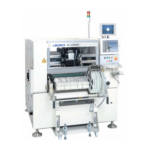
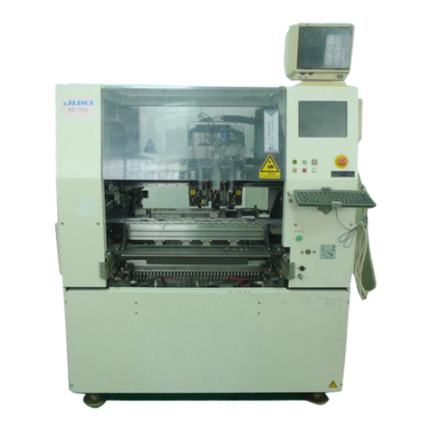
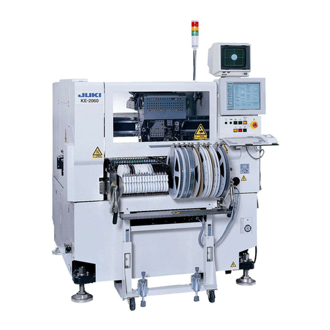
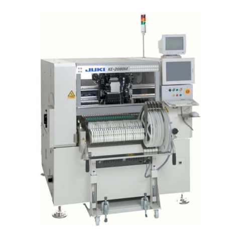
JUKI KE-3010 Operating manual

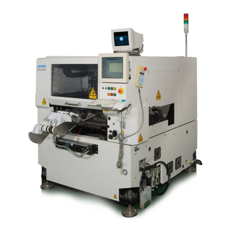
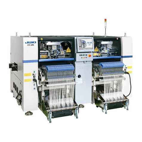
High-Speed Chip Shooter
KE-3010
High-Speed Flexible Mounter
KE-3020V/3020VR
MAINTENANCE GUIDE
JUKI CORPORATION
CUSTOMER SUPPORT DEPARTMENT
ELECTRONIC ASSEMBLY SYSTEMS BUSINESS UNIT

Important
(1) No part of this document may be copied or reproduced without the prior
permission of JUKI Corporation. (Including software and program)
(2) The contents of this document are subject to change without notice.
(3) This manual is prepared with extreme care. However, if you have any question
or find any error or omission in writing, contact our dealer or JUKI Corporation.
(4) JUKI Corporation shall disclaim all the responsibility for any trouble resulting
from the user's abnormal operation regardless of Item (3).
(5) Windows is a registered trademark of Microsoft Corporation USA.
The company names and product names mentioned in this document are
generally registered trademarks or trademarks of the respective companies.

Rev. 2.0
Maintenance Guide
Table of Contents
[1] X-Y UNIT...............................................................................................................1-1
1-1. Replacing the Servomotor...................................................................................1-1
1-1-1. Replacing the X-Motor .............................................................................1-1
1-1-2. Replacing the YL-Motor ...........................................................................1-3
1-1-3. Replacing the YR-Motor...........................................................................1-5
1-2. Replacing the Magnescale ..................................................................................1-7
1-2-1. X-Axis Magnescale Affixing Position........................................................1-9
1-2-2. Y-Axis Magnescale Affixing Position......................................................1-11
1-2-3. Adjusting the Clearance of the Magnescale...........................................1-13
1-2-4. Clearance between the Sensor Head and Y-Axis LM Guide
(Y-axis_XL Board Specifications Only) ..................................................1-16
1-3. Replacing the Limit Sensor and Origin Near Sensor .........................................1-17
1-3-1. Replacing the X-Axis Limit Sensor and
the X-Axis Home Proximity Sensor........................................................1-17
1-3-2. Replacing the Y-Axis Limit Sensor and
the Y-Axis Home Proximity Sensor........................................................1-21
1-3-3. Checking the Limit Sensor Operation ....................................................1-25
1-3-4. Checking the X- and Y-NEAR SENSOR Operation ...............................1-27
1-4. Replacing the Home Position Sensor................................................................1-29
1-4-1. X-Axis ....................................................................................................1-29
1-4-2. Y-Axis ....................................................................................................1-29
1-5. Replacing the Cableveyor .................................................................................1-30
1-5-1. Replacing the X-Axis Cableveyor ..........................................................1-30
1-5-2. Replacing the Y-Axis Cableveyor ..........................................................1-32
1-6. Replacing the Cables in the X/Y Veyor-Cable...................................................1-34
1-6-1. Removing the X Cable ...........................................................................1-34
1-6-2. Checking the Cable Marking (X) ............................................................1-36
1-6-3. Assembling the Cable ............................................................................1-37
1-6-4. Removing the Y Veyor-Cable ................................................................1-40
1-6-5. Placing Marks on the Y Veyor-Cable .....................................................1-40
1-6-6. Assembling the Cable ............................................................................1-41
1-6-7. Wiring around the Head .........................................................................1-48
1-7. Replacing the Cableveyor Link..........................................................................1-51
1-7-1. X Cableveyor Structure and Part Names ...............................................1-51
1-7-2. Detaching the Arm and Lock Stay .........................................................1-51
1-7-3. Separating the Link................................................................................1-52

Rev. 2.0
Maintenance Guide
1-7-4. Connecting the Cableveyor....................................................................1-52
1-7-5. Mounting the Arm and Lock Stay...........................................................1-53
1-7-6. Y Cableveyor Structure and Part Names...............................................1-54
1-7-7. Detaching the Arm and Lock Stay .........................................................1-54
1-7-8. Separating the Link................................................................................1-55
1-7-9. Connecting the Cableveyor....................................................................1-56
1-7-10. Mounting the Arm and Lock Stay...........................................................1-56
1-8. Replacing the X Ball Screw...............................................................................1-58
1-8-1. Preparations for X Ball Screw Replacement..........................................1-58
1-8-2. Removing the X Ball Screw ...................................................................1-60
1-8-3. Mounting the X Ball Screw.....................................................................1-63
1-8-4. Adjusting the X Ball Screw.....................................................................1-66
1-9. Replacing the Y Ball Screw...............................................................................1-70
1-9-1. Preparations for Y Ball Screw Replacement..........................................1-70
1-9-2. Removing the Y Ball Screw ...................................................................1-78
1-9-3. Mounting the Y Ball Screw.....................................................................1-83
1-9-4. Adjusting the Y Ball Screw.....................................................................1-88
[2] HEAD UNIT ..........................................................................................................2-1
2-1. Replacing and Adjusting the Head......................................................................2-1
2-1-1. LNC60 Head............................................................................................2-1
2-1-2. IC Head (KE-3020V)................................................................................2-4
2-1-3. IC Head (KE-3020VR) .............................................................................2-5
2-2. Replacing the Motor............................................................................................2-6
2-2-1. Replacing the Z-Motor (LNC60 Head) .....................................................2-6
2-2-2. Replacing the θ-Motor..............................................................................2-7
2-2-3. Replacing the Z-Motor (IC Head).............................................................2-8
2-2-4. Replacing the θ-Motor (IC Head).............................................................2-9
2-3. Replacing the T-Sensor.....................................................................................2-10
2-4. Replacing the Laser Sensor..............................................................................2-11
2-4-1. Replacing the Laser Sensor (LNC60)....................................................2-11
2-4-2. Replacing the Point Sensor (KE-3020V)................................................2-12
2-4-3. Replacing the FMLA (KE-3020VR)........................................................2-14
2-5. Replacing the Head Up Cylinder.......................................................................2-16
2-6. Replacing the Belts ...........................................................................................2-17
2-6-1. Replacing the Timing Belt Z...................................................................2-17
2-6-2. Replacing the Timing Belt θ...................................................................2-17
2-6-3. IC Head..................................................................................................2-18
2-7. Replacing the Z-Slide Shaft...............................................................................2-20
Rev. 2.0
Maintenance Guide
2-8. Readjustment After Replacement of Head Unit.................................................2-21
[3] PARTS AROUND THE HEAD ..............................................................................3-1
3-1. Replacing the Solenoid Valve Components ........................................................3-1
3-1-1. Replacing the Solenoid Valves ................................................................3-1
3-1-2. Replacing the Filter..................................................................................3-2
3-1-3. Replacing the Filter for Release to Atmosphere ......................................3-2
3-2. Replacing the Bad Mark Sensor (Optional) .........................................................3-3
3-2-1. Sensor Assembly.....................................................................................3-3
3-2-2. Adjusting the Sensor Height ....................................................................3-4
3-2-3. Amplifier...................................................................................................3-5
3-2-4. Assembling the Fiber Unit to the Amplifier ...............................................3-5
3-2-5. Setting the Switches on the Bad Mark Sensor Assembly ........................3-6
3-3. Replacing the HMS .............................................................................................3-6
3-3-1. Replacing the HMS Head ........................................................................3-6
3-3-2. Adjusting the HMS Height........................................................................3-7
3-4. Replacing the Head Board ..................................................................................3-8
3-4-1. Replacing the Head Main Board ..............................................................3-8
3-4-2. Replacing the Servo Amplifier Board .......................................................3-9
[4] OCC ASSEMBLY..................................................................................................4-1
4-1. Replacing the OCC Assembly.............................................................................4-1
4-2. Replacing the CCD Camera and Lens ................................................................4-2
4-3. Replacing the OCC Coaxial/Angle Light Board Assemblies................................4-3
4-4. Replacing the Lens Filter/Light Diffuser...............................................................4-4
4-5. Adjusting the Focus.............................................................................................4-6
4-6. Adjusting the OCC Light Quantity........................................................................4-7
4-7. Readjustment After Replacement of OCC Unit ...................................................4-7
[5] BOARD TRANSPORT UNIT ................................................................................5-1
5-1. Replacing the Transport Belt...............................................................................5-1
5-2. Replacing the Transport Pulley ...........................................................................5-2
5-2-1. Transport Pulley A Assembly: E21117150A0 ..........................................5-2
5-2-2. Transport Pulley B Assembly: E20897210A0 ..........................................5-2
5-3. Replacing the IN and OUT Motors ......................................................................5-3
5-4. Replacing the CENTER Motor ............................................................................5-4
5-5. Replacing the Timing Belt ...................................................................................5-5
5-5-1. Replacing the Timing Belt for Adjustment of the Transport Width............5-5
5-5-2. Replacing the Timing Belt for the Transport Motor ..................................5-7
5-6. Replacing the LEFT and RIGHT Sensors ...........................................................5-8

Rev. 2.0
Maintenance Guide
5-6-1. Replacing the LEFT and RIGHT Sensors
(M and L Board Specifications)................................................................5-8
5-6-2. Replacing the LEFT and RIGHT Sensors (XL Board Specifications).....5-10
5-7. Replacing the WAIT/STOP/C-OUT Sensors .....................................................5-12
5-7-1. Replacing the WAIT Sensor (M and L Board Specifications).................5-12
5-7-2. Replacing the WAIT Sensor (M and L Board Specifications).................5-13
5-7-3. Replacing the WAIT, STOP and C-OUT Sensors
(XL Board Specifications) ......................................................................5-15
5-8. Replacing the Stopper Cylinder.........................................................................5-20
5-9. Replacing the Support Table Home Position Sensor
(BU Home Position Sensor) ..............................................................................5-21
5-10. Replacing the T-PIN Sensor (Optional) .............................................................5-22
5-11. Replacing the Pusher Y Cylinder (Outer Shape Reference) .............................5-23
5-12. Replacing the Pressure Reducing Valve ...........................................................5-24
5-13. Replacing the Centering Pin (Option)................................................................5-25
5-14. Replacing the Support Table Motor (BU Motor) ................................................5-26
5-14-1. Adjusting the Gap between Torque Supporter and Support Motor ........5-27
5-14-2. Adjusting the Tension of the Support Table Driving Timing Belt ............5-28
5-14-3. Placing the Support Table Surface Horizontally.....................................5-29
5-15. Replacing the Support Table Encoder...............................................................5-30
5-16. Replacing the Backup Stopper (for EN Type Only) ...........................................5-31
5-17. Solenoid Valve ..................................................................................................5-32
[6] CAL BLOCK.........................................................................................................6-1
6-1. Replacing the CAL Block Board Assembly..........................................................6-1
6-2. Replacing the Ejector ..........................................................................................6-2
6-3. Replacing the Load Cell ......................................................................................6-3
[7] ATC.......................................................................................................................7-1
7-1. Replacing the Air Cylinder...................................................................................7-1
7-2. Replacing the ATC OPEN and CLOSE Sensors .................................................7-4
7-3. Adjusting the Speed Controller............................................................................7-4
[8] VCS.......................................................................................................................8-1
8-1. Replacing the CCD Camera Lens
(Replace the CCD Camera and Lens as S-VCS Camera Assembly.).................8-1
8-2. Replacing the Standard S-VCS →Optional S-VCS Switching Cylinder..............8-3
8-3. Replacing the Light Boards .................................................................................8-4
8-3-1. Transmission Light Board, Coaxial Light Board .......................................8-4
8-3-2. Downward Light Board, Side Light Board ................................................8-5

Rev. 2.0
Maintenance Guide
[9] FEEDER BANK AND REPLACEMENT TABLE (OPTIONAL).............................9-1
9-1. Common Parts and Units for Mechanical Feeder and Electric Feeder................9-1
9-1-1. Replacing the Mechanical Valve (Optional Replacement Table) .............9-3
9-1-2. Replacing the Bank-up Cylinder (Optional Replacement Table)..............9-5
9-1-3. Adjusting the Speed Controller of the Bank-Up Cylinder
(Optional Replacement Table) .................................................................9-7
9-1-4. Replacing the Bank-Up Detection Sensor
(Optional Replacement Table) .................................................................9-8
9-1-5. Replacing the Selector Switch (Optional Replacement Table).................9-9
9-1-6. Replacing the Cylinder for Drive Cylinder Unit Up/Down
(Specifications Common to Optional Electric and
Mechanical Replacement Tables)..........................................................9-10
9-1-7. Replacing the Cylinder Sensor for Drive Cylinder Unit Up/Down
(Specifications Common to Optional Electric and
Mechanical Replacement Tables)..........................................................9-11
9-1-8. Replacing the Electric Bank Support Cylinder
(Optional Replacement Table) ...............................................................9-12
9-2. Bank and Replacement Table for Mechanical Feeder.......................................9-14
9-2-1. Replacing the Drive Cylinder
(Mechanical Fixed Bank and Mechanical Replacement Table) .............9-15
9-2-2. Replacing the Drive Cylinder
(Specifications Common to Optional Electric and
Mechanical Replacement Tables)..........................................................9-17
9-2-3. Adjusting the Speed Controller of the Drive Cylinder.............................9-19
9-2-4. Replacing the Feeder Bank Board (Optional) ........................................9-19
9-2-5. Replacing the Bank PCB .......................................................................9-20
9-3. Bank and Replacement Table for Electric Feeder.............................................9-21
9-3-1. Replacing the Bank PCB .......................................................................9-23
9-3-2. Replacing the Connector Cable .............................................................9-24
9-3-3. Replacing the Connector for Off-Line Setup ..........................................9-25
9-4. Trash Box..........................................................................................................9-26
[10] PNEUMATIC UNITS ...........................................................................................10-1
10-1. Replacing the Digital Pressure Switch...............................................................10-1
10-1-1. Adjusting the Digital Pressure Switch (Positive Pressure) .....................10-2
10-1-2. Adjusting the Digital Pressure Switch (Negative Pressure)....................10-4
10-2. Replacing the Filter Element .............................................................................10-6
10-3. Replacement of Vacuum Pump Parts ...............................................................10-7
[11] SWITCH AND COVER RELATED......................................................................11-1

Rev. 2.0
Maintenance Guide
11-1. Replacing the Push-Button Switch ....................................................................11-1
11-1-1. Replacing the Push-Button Switch
(Machine with the Standard Specifications) ...........................................11-1
11-1-2. Replacing the Push-Button Switch
(Machine with the EN Specifications) ....................................................11-3
11-2. Replacing the EMERGENCY STOP Switch ......................................................11-4
11-3. Replacing the Cover Open Switch.....................................................................11-5
11-4. Replacing the Safety Cover Lock Cylinder ........................................................11-6
[12] REPLACING AND ADJUSTING THE FEEDER FLOAT SENSOR ....................12-1
12-1. Replacing the Sensor and Adjusting the Height ................................................12-1
12-2. Checking and Adjusting the Sensor Operation..................................................12-8
[13] OTHER UNITS....................................................................................................13-1
13-1. LCD Monitor ......................................................................................................13-1
13-1-1. Replacing the LCD Monitor....................................................................13-1
13-1-2. Setting Up the Touch Panel ...................................................................13-2
13-2. Replacing the System Disk ...............................................................................13-4
13-2-1. Replacing the SSD ................................................................................13-4
13-2-2. Setting Up the BIOS...............................................................................13-7
13-2-3. Setting Up the Network
(Setup is required when communicating with the IS.) ..........................13-13
13-2-4. KE-3010/3020V/3020VR System Programs ........................................13-24
13-2-5. Upgrading the System Version ............................................................13-33
13-2-6. Installing the Main Unit Software into the SSD for the White List Type
Antivirus Software (Optional) ...............................................................13-39
13-3. Load Cell (Optional) ........................................................................................13-41
13-3-1. Replacing the Load Cell.......................................................................13-41
13-4. Coplanarity Sensor (Optional) .........................................................................13-43
13-4-1. Replacing the Sensor...........................................................................13-43
13-4-2. Changing the IP Address of the Coplanarity CPU ...............................13-45
13-4-3. Changing the Mounter Settings ...........................................................13-49
[14] ELECTRICAL COMPONENTS...........................................................................14-1
14-1. Layout of Electrical Components.......................................................................14-1
14-1-1. Layout of Electrical Components (M and L Board Specifications) .........14-1
14-1-2. Layout of Electrical Components (XL Board Specifications) ..................14-3
14-2. Power Supply Unit.............................................................................................14-5
14-2-1. Structure of Power Supply Unit (M and L Board Specifications) ............14-5
14-2-2. Structure of Power Supply Unit (XL Board Specifications)...................14-12

Rev. 2.0
Maintenance Guide
14-3. Control Unit .....................................................................................................14-19
14-3-1. Structure of Control Unit ......................................................................14-19
14-3-2. CPU Board (40103723) .......................................................................14-20
14-3-3. Position Board (40044540) ..................................................................14-21
14-3-4. IEEE1394 Board (40048003)...............................................................14-22
14-3-5. ETHER-MAIN Board (40048066).........................................................14-23
14-3-6. IP-X7 BASE ASM (40071283), IP-X7 SUB ASM (40071293) ..............14-24
14-3-7. MOUSE/KEYBOARD Selector (40003281) .........................................14-25
14-3-8. SUPERIMPOSE Board (40048082).....................................................14-26
14-3-9. SCM3 Board (40114496) Laser Board for FMLA
(KE-3020VR Only) ...............................................................................14-27
14-3-10. S-Light Control (40108607)..................................................................14-27
14-3-11. Feeder Board (40047560)....................................................................14-27
14-3-12. S-XY Relay Board (40106795) ............................................................14-27
14-3-13. MAGNETIC SCALE Board (40095130) (XL Specifications Only) ........14-27
14-3-14. BASE IO Board (40071680).................................................................14-27
14-4. ATX Power Supply (40048006) .......................................................................14-28
14-4-1. Battery Unit (40048007).......................................................................14-29
14-5. X-Y Unit...........................................................................................................14-31
14-5-1. Structure of X-Y Unit ............................................................................14-31
14-5-2. Display Indication of XY Servo Amplifier..............................................14-32
14-6. Z-θUnit ...........................................................................................................14-33
14-6-1. Structure of Z-θUnit.............................................................................14-33
14-6-2. LED Indications....................................................................................14-34
14-7. Transport Unit..................................................................................................14-35
14-7-1. Structure of Transport Unit...................................................................14-35
14-7-2. Adjusting the BASE I/O Board (40071680) ..........................................14-39
14-7-3. Adjusting the Stepping Driver ..............................................................14-39
14-8. Head Unit ........................................................................................................14-41
14-8-1. S-HEAD MAIN PCB ASM (40106799) .................................................14-41
14-8-2. Adjusting the Point Sensor...................................................................14-43
14-9. Covers.............................................................................................................14-44
14-9-1. Structure of Operation Unit ..................................................................14-44
14-9-2. Jumper Switch Settings on the Operation Board Assembly.................14-44
14-9-3. Mounting Switches onto the Operation Switchboard ...........................14-46
14-10. Replacing the Fuse of the AC Input Unit...................................................14-52
14-11. ETF Power Supply (Option for M and L Board Specifications ) ................14-53
14-11-1. Replacing the ETF Power Supply Unit.................................................14-53

Rev. 2.0
Maintenance Guide
[15] AUTO BOARD WIDTH ADJUSTMENT (OPTIONAL)........................................15-1
15-1. Assembling the AWC Bracket ...........................................................................15-1
15-2. Assembling to the Machine Main Unit ...............................................................15-2
15-2-1. Mounting the AWC Bracket Assembly ...................................................15-2
15-2-2. Mounting the Origin Sensor Dog............................................................15-3
15-3. Support Pin Detection Sensor ...........................................................................15-4
15-3-1. Mounting the Support Pin Detection Sensor ..........................................15-4
15-4. Bundling the Support Pin Detection Sensor ......................................................15-6
15-4-1. Mounting the Support Pin Detection Sensor (Bundling the Cables).......15-6
15-5. Adjusting the Sensor .........................................................................................15-7
15-6. Mounting the Driver Bracket..............................................................................15-7
15-7. Setting the Driver...............................................................................................15-8
15-8. Mounting the Support Pin Sensor Dog ..............................................................15-9
[16] FEEDER POSITION INDICATOR (FPI) (OPTIONAL)........................................16-1
16-1. Detaching the FPI (Front) (M and L Board Specifications) ................................16-1
16-2. Detaching the FPI (Rear) (M and L Board Specifications).................................16-2
16-3. Structure of Parts and Components inside FPI (Front)
(M and L Board Specifications) .........................................................................16-3
16-4. Structure of Parts and Components inside FPI (Rear)
(M and L Board Specifications) .........................................................................16-4
16-5. Detaching the FPI (Front) (XL Board Specifications).........................................16-5
16-6. Detaching the FPI (Rear) (XL Board Specifications) .........................................16-6
16-7. Structure of Parts and Components inside FPI (Front)
(XL Board Specifications)..................................................................................16-7
16-8. Structure of Parts and Components inside FPI (Rear)
(XL Board Specifications)..................................................................................16-8
[17] OFFSET PLACEMENT AFTER SOLDER SCREEN-PRINTING LIGHT
(OPTIONAL).......................................................................................................17-1
17-1. Replacing the Offset Placement after Solder Screen-Printing Light ..................17-1
17-2. Adjusting the Light Quantity of the Offset Placement after
Solder Screen-Printing Light .............................................................................17-2
[18] TAPE CUTTER (OPTIONAL) .............................................................................18-1
18-1. Overall Drawing.................................................................................................18-1
18-2. Replacing the Tape Cutter Main Unit ................................................................18-2
18-3. Replacing the Tape Cutter Blade ......................................................................18-5
[19] CVS (OPTIONAL)...............................................................................................19-1
19-1. Replacing the CONTACT SUB UNIT ................................................................19-1

Rev. 2.0
Maintenance Guide
19-2. Replacing the PCB............................................................................................19-4
[20] ROTARY SOLDER TRANSFER UNIT (OPTIONAL)..........................................20-1
20-1. Replacing the Squeegee...................................................................................20-1
20-2. Replacing the Pan.............................................................................................20-3
20-3. Replacing the Motor..........................................................................................20-4
20-4. Checking the Pan Mounting Status...................................................................20-6
[21] MULTI-CODE READER (OPTIONAL )...............................................................21-1
21-1. Replacing the Multi-code Reader (Head) .........................................................21-1
21-2. Replacing the Multi-code Reader (Transport)...................................................21-2
[22] PLACEMENT MONITOR (OPTIONAL)..............................................................22-1
22-1. Replacing the LNC61/62...................................................................................22-1
22-2. Replacing the EPV61/62...................................................................................22-2
22-3. Replacing the Head Up Cylinder (KE-3020V/3020VR)......................................22-3
22-4. Obtaining the Offset After Replacement............................................................22-5
22-5. Checking the Images After Replacement..........................................................22-6
22-5-1. Calibration Application...........................................................................22-6
22-5-2. EPV Calibration .....................................................................................22-9
APPENDIX
JIG LISTS.................................................................................................................... A-1

Rev. 2.0
Maintenance Guide
1-1
[1] X-Y UNIT
1-1. Replacing the Servomotor
1-1-1. Replacing the X-Motor
<M and L board specifications>
1) Remove the SL6061292TN, NM6060001SC to detach the COVER_SUL_F_M.
2) Loosen the COUPLING_X_screw (do not remove the screw at this time) and disconnect the
connector of the SERVO MOTOR 750W cable.
3) Remove the SL6062042TN and replace the SERVO MOTOR 750W.
4) Reassemble the components in the reverse order of disassembly.
∗The clearance between the COUPLING and motor is 8 mm.
The tightening torque of the COUPLING_X_screw is 3.4 N⋅m. (Figure 1-1-1-4)
Carefully check the motor orientation.
Figure 1-1-1-1 Removal of Cover of Machine with M and L Board Specifications
REAR
FRONT
COVER_SUL_F_M
SL6061292TN (
Inside of left side of machine
×
3) NM6060001SC (×2)
8
Figure 1-1-1-4
Figure 1-1-1-3
SERVO MOTOR 750W
SL6062042TN
(
×
4
)
Figure 1-1-1-2
COUPLING_X_screw
COUPLING_X

Rev. 2.0
Maintenance Guide
1-2
<XL board specifications>
1) Remove the SL6061292TN to detach the CABLE_SIDE_COVER.
2) In the same manner as described for the machine with the M and L board specifications,
loosen the COUPLING_X_screw (do not remove the screw at this time) and disconnect the
connector of the SERVO MOTOR 750W cable.
3) Remove the SL6062042TN and replace the SERVO MOTOR 750W.
4) Reassemble the components in the reverse order of disassembly.
∗The clearance between the COUPLING and motor is 8 mm.
The tightening torque of the COUPLING_X_screw is 3.4 N⋅m. (Figure 1-1-1-4)
Carefully check the motor orientation.
Figure 1-1-1-5 Removal of Cover of Machine with XL Board Specifications
REARFRONT
CABLE_SIDE_COVER (40097773)
SL6061292TN (×2)
Right side of machine
REAR FRONT
Inside of right side of machine
SL6061292TN (×6)
Figure 1-1-1-7
SERVO MOTOR 750W
SL6062042TN (
×
4)
Figure 1-1-1-6
COUPLING_X
COUPLING_X_screw

Rev. 2.0
Maintenance Guide
1-3
1-1-2. Replacing the YL-Motor
<M and L board specifications>
1) Remove the SL3061232TN to detach the COVER_FBL.
2) Remove the SL6041092TN to detach the SUB_COVER_FUL.
3) Loosen the COUPLING_Y_screw (do not remove the screw at this time) and disconnect the
connector of the SERVO MOTOR 1500W cable.
4) Remove the SM6082002TN and replace the SERVO MOTOR 1500W.
5) Reassemble the components in the reverse order of disassembly.
∗The clearance between the COUPLING and motor is 4 mm. The tightening torque of the
COUPLING_Y_screw is 7 N⋅m. (Figure 1-1-2-4)
SL6041092TN (×4)
A B
COVER_FBL
View of A
SL3061232TN (×2)
View of B
SL3061232TN (
×
2)
SUB_COVER_FUL
Figure 1-1-2-1 Removal of Cover of Machine with M and L Board Specifications
COUPLING_Y
COUPLING_Y_screw
Figure 1-1-2-2 Figure 1-1-2-3
4
SM6082002TN (
×
4)
SERVO MOTOR 1500W
Figure 1-1-2-4

Rev. 2.0
Maintenance Guide
1-4
<XL board specifications>
1) Remove the SL3061232TN and SL6040892TN, detach the COVER_FBL_XL.
2) In the same manner as described for the machine with the M and L board specifications,
loosen the COUPLING_Y_screw (do not remove the screw at this time) and disconnect the
connector of the SERVO MOTOR 1500W cable.
3) Remove the SM6082502TN and replace the SERVO MOTOR 1500W.
4) Reassemble the components in the reverse order of disassembly.
∗The clearance between the COUPLING and motor is 8 mm.
The tightening torque of the COUPLING_X_screw is 3.4 N⋅m. (Figure 1-1-2-4)
Secure from the
back of the cover.
SL6040892TN
SL3061232TN (×2)
COVER_FBL_XL
SL3061232TN
(×2)
A B
View of A View of B
Figure 1-1-2-5 Removal of Cover of Machine with XL Board Specifications
SM6082502TN (×4)
SERVO MOTOR 1500W
COUPLING_Y
COUPLING_Y_screw
Figure 1-1-2-6 Figure 1-1-2-7

Rev. 2.0
Maintenance Guide
1-5
1-1-3. Replacing the YR-Motor
<M and L board specifications>
1) Remove the SL3061232TN to detach the COVER_FBR.
2) Remove the SL6041092TN, NM3060810SF to detach the SUB_COVER_FUR.
3) Loosen the COUPLING_Y_screw (do not remove the screw at this time) and disconnect the
connector of the SERVO MOTOR 1500W cable.
4) Remove the SL6082002TN and replace the SERVO MOTOR 1500W.
5) Reassemble the components in the reverse order of disassembly.
∗The clearance between the COUPLING and motor is 4 mm. The tightening torque of the
COUPLING_Y_screw is 7 N⋅m. (Figure 1-1-3-4)
Figure 1-1-3-1 Removal of Cover of Machine with M and L Board Specifications
SL3061232TN (
×
2)
SL6041092TN (×4)
SL3061232TN (×2)
NM3060810SF
View of A View of B
SUB_COVER_FUR
COVER_FBR
BA
COUPLING_Y_screw
COUPLING_Y
Figure 1-1-3-2 4
Figure 1-1-3-3
SERVO MOTOR 1500W
SM6082002TN (
×
4)
Figure 1-1-3-4

Rev. 2.0
Maintenance Guide
1-6
View of A
<XL board specifications>
1) Remove the SL6061292TN, SL3061232TN to detach the COVER_FBR_XL.
2) In the same manner as described for the machine with the M and L board specifications,
loosen the COUPLING_Y_screw (do not remove the screw at this time) and disconnect the
connector of the SERVO MOTOR 1500W cable.
3) Remove the SL6082502TN and replace the SERVO MOTOR 1500W.
4) Reassemble the components in the reverse order of disassembly.
∗The clearance between the COUPLING and motor is 4 mm. The tightening torque of the
COUPLING_Y_screw is 7 N⋅m. (Figure 1-1-3-4)
Figure 1-1-3-5 Removal of Cover of Machine with XL Board Specifications
Figure 1-1-3-6 Figure 1-1-3-3
A
COVER_FBR_XL
B
View of B
SL3061232TN SL6061292TN
SERVO MOTOR 1500W
SM6082502TN (
×
4)
COUPLING_Y_screw
COUPLING_Y

Rev. 2.0
Maintenance Guide
1-7
1-2. Replacing the Magnescale
1) For the machine with the XL board specifications, detach the side cover. For the machine
with the M and L board specifications, do not detach the side cover and move to step 2).
Figure 1-2-1
Cross-section of L-side
SL6040892TN ×5
NM3060810SF ×4
For details about how to detach the
CABLE_SIDE_COVER (40097773), see
Figure 1-1-1-5 stated in section 1-1,
“Replacing the Servomotor”.
Cross-section of R-side
NM3060810SF ×4
COVER_SML_XL (40098794)
COVER_SMR_XL (40098793)

Rev. 2.0
Maintenance Guide
1-8
2) Detach the magnescale head from the bracket.
3) Peel off the old magnescale.
4) Degrease the magnescale mounting surface and magnescale completely.
Note 1: Before replacing the magnescale, put the magnescale near the machine and leave it
for 1 hr. or longer to make the temperature of the magnescale similar to that of the
machine.
Note 2: “Mecha fine mate” is recommended for the degreasing agent.
Note 3: Deviation amount when compared to the specified value of the magnescale in the
X-direction: ±0.1 mm or less.
Note 4: Do not put any magnet, such as magnetized screwdriver or support pin close to the
magnescale. Doing so may cause the magnescale to malfunction.
Note 5: The magnescale has the affixing orientation. Affix the magnescale in the same
orientation as the S/N shown in the Figure. For details about magnescale to be used,
see the List below.
List of magnescale specifications
M and L board specifications XL board specifications
Magnescale X (40113692) Magnescale X (40113693)
KE-3010 Magnescale Y (40091396) Magnescale Y_XL (40048080)
Magnescale X (40044528)
KE-3020V/KE-3020VR Magnescale Y (40091396) Magnescale Y_XL (40048080)
Figure 1-2-2 Affixing Orientation of the Magnescale (Main Body Top View)
(∗S/N: Serial No. of the magnescale)
Note 1: Orientation of Serial No. of
Machine with XL Specifications
Magnescale Y
Note 1
Note 1
Magnescale X
“M and L board
specifications”
“XL board
specifications”
Magnescale Y_XL
∗See the List shown above.
FR
O
NT
REAR

Rev. 2.0
Maintenance Guide
1-9
1-2-1. X-Axis Magnescale Affixing Position
1) With the X-axis magnescale affixing jig (40094362) put tightly in contact with the front of the
LM-guide and the bottom of the X-axis frame, make the magnescale in contact with the
X-axis magnescale affixing jig to affix the magnescale.
A marking-off line is provided at the affixing start position on the left when viewed from the
front.
Adjust the end face position of the magnescale to the marking-off line and affix the
magnescale.
Specification value: Magnescale affixing position (distance deviation in parallel to the
head moving direction) ±0.1 mm
Cut
surface
112.5±0.1(KE-3020V,VR)
59.5±0.1(KE-3010) 181.5±0.1(KE-3020V,VR)
128.5±0.1(KE-3010)
Center of Z-phase marking
Magnescale affixing position
and direction
X_LM guide
L side of
machine
Figure 1-2-1-1 Magnescale Affixing Positions of M and L Board Specifications
Cut
surface
119±0.1(KE-3020V,VR)
71.5±0.1(KE-3010)
X_LM guide
Magnescale affixing
position and direction
L side of
machine
188±0.1(KE-3020V,VR)
140.5±0.1(KE-3010)
Center of
Z-phase marking
Figure 1-2-1-2 Magnescale Affixing Positions of X L Board Specifications
This manual suits for next models
2
Table of contents
Other JUKI Industrial Equipment manuals

JUKI
JUKI KE-750 User manual

JUKI
JUKI AW-3S User manual

JUKI
JUKI AF05 User manual

JUKI
JUKI MEB-3200C User manual

JUKI
JUKI KE-2050 Operating manual

JUKI
JUKI LK-1900B series Instruction Manual

JUKI
JUKI PS-900-13090 User manual

JUKI
JUKI L-1A User manual

JUKI
JUKI TR6SNR Operating manual

JUKI
JUKI JX-100 User manual