manuals.online logo
Brands
  1. Home
  2. •
  3. Brands
  4. •
  5. KI
  6. •
  7. Indoor Furnishing
  8. •
  9. KI U Series User manual

KI U Series User manual

Assemble units as described herein only. To do otherwise
may result in instability. All screws, nuts and bolts must be
tightened securely and must be checked periodically after
assembly. Failure to assemble properly, or to secure parts
may result in assembly failure and personal injury.
Assembly Instructions
U-Series Pedestals
July 2015
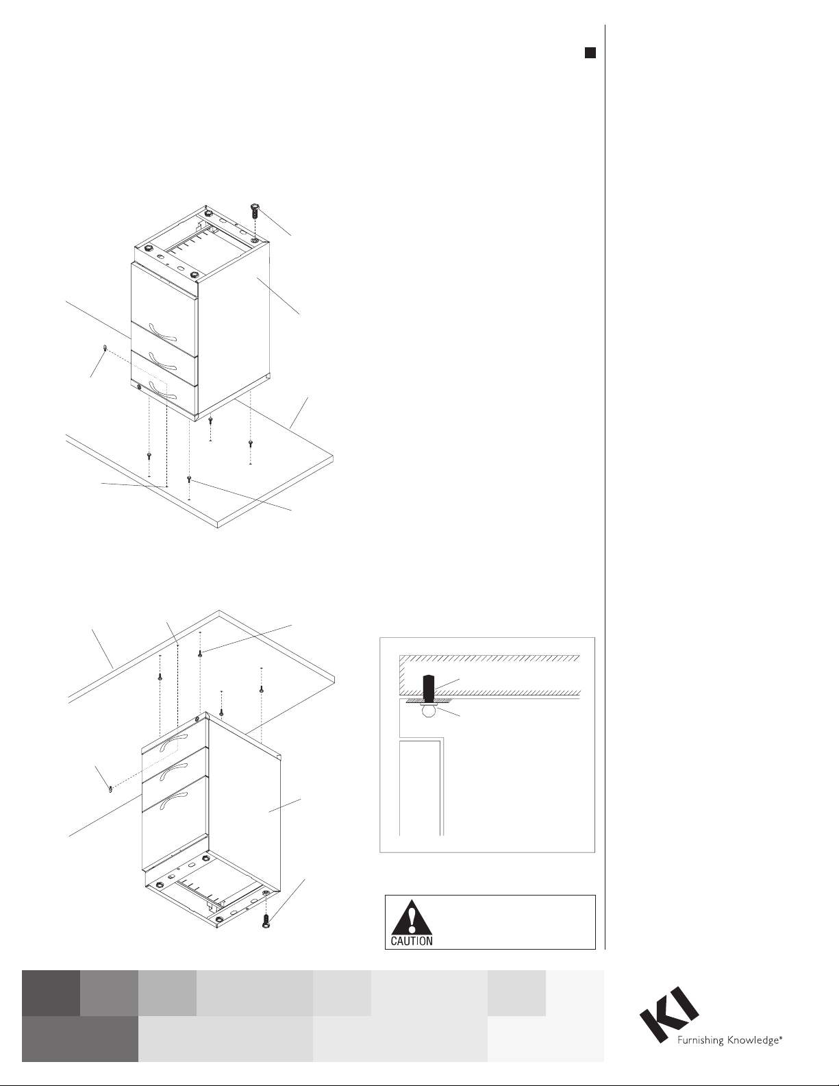
Mounting Worksurface
Supporting Pedestals to
Worksurface
Method “A”
1. To avoid scratching the
worksurface, place face down on a
soft protective surface (Figure 1).
Note: For installation of pedestal
to worksurface without holes
pre-drilled to underside, see
Figure 3, next page.
2. Determine on which side of
the worksurface the pedestal
will install to, then twist four
hanger bolts into the 13/64” dia.
worksurface holes. Caution: Do
not over-tighten bolts.
3. Position pedestal so hanger bolts
insert through top of pedestal
at larger opening of keyhole
slots. Then slide pedestal back
to engage four hanger bolts in
smaller slot of keyholes
(Figure 1).
4. Open top drawer of pedestal
and locate front, center hole in
pedestal. Make sure pedestal
mounting hole aligns with
predrilled hole in worksurface
and install thumbscrew through
pedestal, into worksurface to
secure pedestal in place
(Detail A).
5. Once pedestal is secured to
underside of worksurface, and
worksurface is right-side up
at its final location on-site,
adjust the four glides under the
pedestal to achieve a level, stable
worksurface.
Method “B”
Note: This method should
be used only when attaching
a pedestal to worksurface that
cannot be placed face down on
the floor.
1. Follow notes and instructions
in Method “A” excluding step 1
(Figure 2).
Caution: To avoid injury this
operation requires more than one
person to install pedestal.
Guide Bracket Installation
5. At the location where a rolling door is to
be installed, remove the intersection top
cap if not already done so (Figure 2).
6. At the isle side of the end-of-run trim,
position two clamp blocks as illustrated,
with mounting holes showing out and
insert blocks into the opening as shown
(Detail C). Place one block at the top of
the attaching trim slot and slide one
bracket to the bottom of the trim (Figure 2
& Detail B).
Important: For the step below, ensure the
“U” shape of the upper and lower guide
brackets face each other as illustrated.
Tighten screws into the plastic blocks
until brackets are snug but can still slide
for final adjustment.
7. Next, correctly position the upper and
lower door guide brackets in place as
illustrated and install using two #10-16 x
3/4” Phillips flat head self-drilling Tek
Screws. Do not tighten completely at this
time (Figure 2, Detail C).
predrilled hole
thumbscrew
Detail A
worksurface
thumbscrew
hole hanger
bolt
pedestal
thumbscrew
adjustable
glide
Method “B”
Figure 2
Method “A”
Figure 1
hanger
bolt
worksurface
pedestal
adjustable
glide
thumbscrew
hole
thumbscrew
Assemble units as described herein only. To do otherwise
may result in instability. All screws, nuts and bolts must be
tightened securely and must be checked periodically after
assembly. Failure to assemble properly, or to secure parts
may result in assembly failure and personal injury.
2
U-Series Pedestals
Assembly Instructions
1330 Bellevue Street • P.O. Box 8100 • Green Bay, WI 54308-8100 • Tel 1-800-424-2432 • www.ki.com
© 2015 Krueger International, Inc. All Rights Reserved • Code KI-62569/KI/PDF/0715
Door Installation
8. The door guide bracket installed to clamp
block should be snug, but not tight. Slide the
upper door guide bracket upward in the slot, to
make room for installation of rolling door (Figure
3, Detail D).
Note: The four (two at each bracket) #10-16 x
3/4” self-drilling Tek screws for final door guide
bracket attachment to face of should not be
installed at this time.
pedestal
caster
mounting
plate
#10 x / "
12
screw
edge of pedestal
9 /”
3
8
2 /”
13 16
7 /”
12
1 /”
1
16 1 /”
9
16
15 / ” (for 20” pedestal)
15
16
19 / ” (for 24” pedestal)
15
16
22 / ” (for 30” pedestal)
15
16
front edge of worksurface
front/center
caster (small)
5/ -18 lock
16
washer nut
Figure 4
Door Installation
8. The door guide bracket installed to clamp
block should be snug, but not tight. Slide the
upper door guide bracket upward in the slot, to
make room for installation of rolling door (Figure
3, Detail D).
Note: The four (two at each bracket) #10-16 x
3/4” self-drilling Tek screws for final door guide
bracket attachment to face of should not be
installed at this time.
pedestal
caster
mounting
plate
#10 x / "
12
screw
edge of pedestal
9 /”
3
8
2 /”
13 16
7 /”
12
1 /”
1
16 1 /”
9
16
15 / ” (for 20” pedestal)
15
16
19 / ” (for 24” pedestal)
15
16
22 / ” (for 30” pedestal)
15
16
front edge of worksurface
front/center
caster (small)
5/ -18 lock
16
washer nut
Figure 3
Mobile Pedestal Casters &
Free Standing Pedestal Glides
Installation
Note: Four plate-mounted casters
or glides and a small anti-tip
caster are provided for installation
to the base of the pedestal. The
plate mounted casters or glides
are installed in the four corners.
The small caster will fasten to the
lower drawer bracket, if included.
1. Carefully lay pedestal onto a soft
protective surface, on it’s
back-side as illustrated
(Figure 4).
2. Slide each caster or glide plate
to nest into the formed tabs
under the appropriate corner of
the pedestal. Properly nested,
a single mounting hole in the
base of each corner caster will
align with a pre-drill hole in
the underside of the pedestal.
Secure each caster or glide to the
underside of the pedestal with one
#10 x 1/2” screw (Figure 4).
3. If applicable, extend the bottom
drawer of the pedestal out to
expose the center caster mount.
Fasten the anti-tip caster to the
drawer bracket and secure firmly
in place with the 5/16-18 lock
washer nut.
21150-2

Other KI Indoor Furnishing manuals

KI Uniframe Conver User manual

KI

KI Uniframe Conver User manual

KI 700 Series User manual

KI

KI 700 Series User manual

KI Trek User manual

KI

KI Trek User manual

KI Rapture Stack Chair User manual

KI

KI Rapture Stack Chair User manual

KI Soltice Guide

KI

KI Soltice Guide

KI Engage Task Chair Installation instructions

KI

KI Engage Task Chair Installation instructions

KI Likha Casegoods User manual

KI

KI Likha Casegoods User manual

KI Pirouette User manual

KI

KI Pirouette User manual

KI Impress Ultra Installation guide

KI

KI Impress Ultra Installation guide

KI 700 Series User manual

KI

KI 700 Series User manual

KI Ruckus Tote Storage User manual

KI

KI Ruckus Tote Storage User manual

KI WorkUp HF User manual

KI

KI WorkUp HF User manual

KI System 3000 Countertop User manual

KI

KI System 3000 Countertop User manual

KI Aristotle Casegoods Wall-Mounted Overhead... User manual

KI

KI Aristotle Casegoods Wall-Mounted Overhead... User manual

KI Smart Lift User manual

KI

KI Smart Lift User manual

KI Altus Task Seating Installation instructions

KI

KI Altus Task Seating Installation instructions

KI CrossRoads Shelving Single Face Metal with Back... User manual

KI

KI CrossRoads Shelving Single Face Metal with Back... User manual

KI Piretti Torsion Installation instructions

KI

KI Piretti Torsion Installation instructions

KI WireWorks Tech Panel User manual

KI

KI WireWorks Tech Panel User manual

KI All Terrain Binder Tower User manual

KI

KI All Terrain Binder Tower User manual

KI Intellect Chair Guide

KI

KI Intellect Chair Guide

KI WorkZone Series User manual

KI

KI WorkZone Series User manual

KI All Terrain ATSW45 User manual

KI

KI All Terrain ATSW45 User manual

KI Extol Installation instructions

KI

KI Extol Installation instructions

Popular Indoor Furnishing manuals by other brands

Stanley HTC-275S Use and care guide

Stanley

Stanley HTC-275S Use and care guide

VonHaus 2500359 user manual

VonHaus

VonHaus 2500359 user manual

Robern CRAFT Series Important safety instructions

Robern

Robern CRAFT Series Important safety instructions

Argos Aurelie 531/6854 Assembly lnstructions

Argos

Argos Aurelie 531/6854 Assembly lnstructions

Pick Up PAULINE BKO Assembly instructions

Pick Up

Pick Up PAULINE BKO Assembly instructions

Fresco Allure Connect-12 instructions

Fresco

Fresco Allure Connect-12 instructions

burgbad Sana M1153 Instructions and operating manual

burgbad

burgbad Sana M1153 Instructions and operating manual

Zoovilla PTH0201721810 Care Instructions

Zoovilla

Zoovilla PTH0201721810 Care Instructions

Accuride 2109 installation guide

Accuride

Accuride 2109 installation guide

BLUM Aventos HK-S Assembly instructions

BLUM

BLUM Aventos HK-S Assembly instructions

Vinsetto 838-396V80 manual

Vinsetto

Vinsetto 838-396V80 manual

Emmezeta SEVILLA SEVK31 Assembling instructions

Emmezeta

Emmezeta SEVILLA SEVK31 Assembling instructions

Urban Barn Gabi 222389002 Assembly instructions

Urban Barn

Urban Barn Gabi 222389002 Assembly instructions

Forte MTBR711 Assembling Instruction

Forte

Forte MTBR711 Assembling Instruction

StyleWell BF-25648-WA Use and care guide

StyleWell

StyleWell BF-25648-WA Use and care guide

PEFC 875/4176 Assembly instructions

PEFC

PEFC 875/4176 Assembly instructions

GEIGER Tablet Installation principles

GEIGER

GEIGER Tablet Installation principles

Safavieh Furniture Ryder CNS5719 quick start guide

Safavieh Furniture

Safavieh Furniture Ryder CNS5719 quick start guide

manuals.online logo
manuals.online logoBrands
  • About & Mission
  • Contact us
  • Privacy Policy
  • Terms and Conditions

Copyright 2025 Manuals.Online. All Rights Reserved.