manuals.online logo
Brands
  1. Home
  2. •
  3. Brands
  4. •
  5. KI
  6. •
  7. Indoor Furnishing
  8. •
  9. KI Vertical Cable Manager User manual

KI Vertical Cable Manager User manual

Assemble units as described herein only. To do otherwise
may result in instability. All screws, nuts and bolts must be
tightened securely and must be checked periodically after
assembly. Failure to assemble properly, or to secure parts
may result in assembly failure and personal injury.
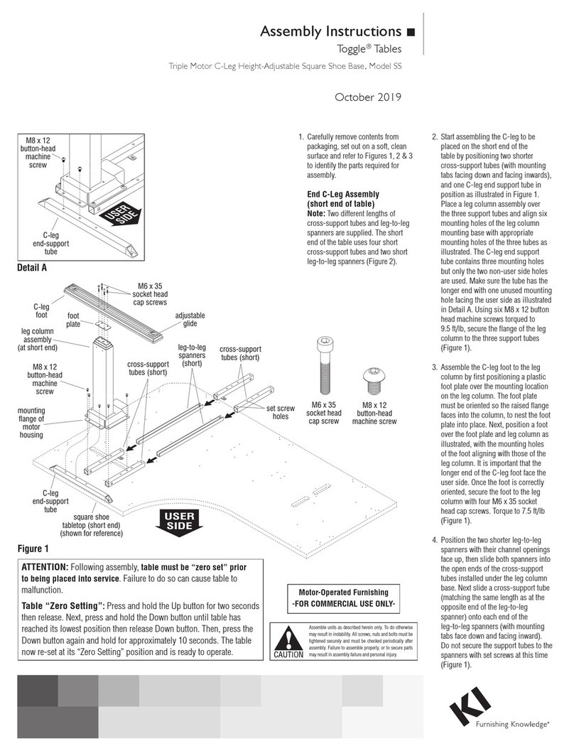
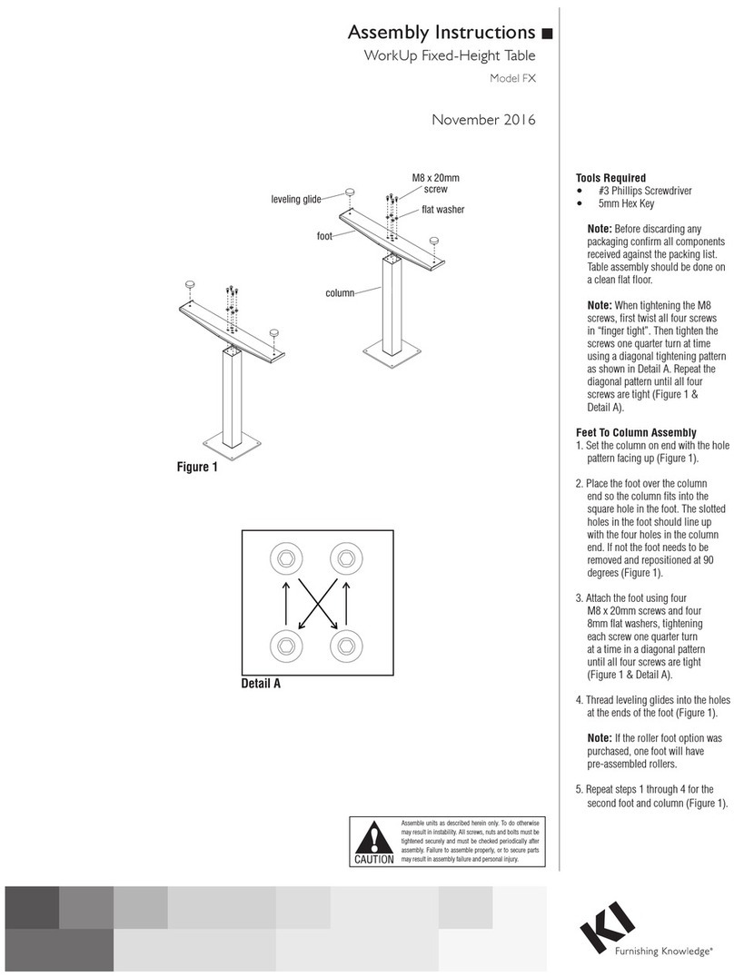
Assembly Instructions
Vertical Cable Manager
November 2018
Required Tools
• Cordless Power Drill
• Screwdriver
Vertical Cable Manager Installation
Note: If the Vertical Cable Manager
will mount to the underside of
the tabletop, proceed to “Tabletop
Mounted Cable Manager”
instructions below. If the Cable
Manager will mount to the underside
of the wire trough, proceed to “Wire
Trough Mounted Cable Manager”
instructions below.
Tabletop Mounted Cable Manager
1. Position the top mounting plate
underneath the back, non-user side
of the tabletop at the desired location.
Assure that the power cord can be
routed easily to the mounting plate
and to a power source (Figure 1).
2. Using the top mounting plate as a
template underneath the table, align
the unit straight, and 1/4” back from
the table edge, then mark the two
mounting hole locations and move
the plate away (Figure 1).
3. Carefully bore a 3/32” pilot hole at
the center of each marked location,
underneath the tabletop using a cordless
power drill. Take care to not drill too
deep, piercing the table top (Figure 1).
4. Align the mounting holes of the top
mounting plate with the pre-drilled
holes underneath the tabletop. Secure
the mounting plate to the table using
two #9 x 1” flat head screws. Take care
to not over tighten (Figure 2).
5. Proceed to page 2 for “Vertical Cable
Manager Installation” instructions.
marked for
drilling
cordless
power drill
tabletop
leg column
(adjusted to
maximum
height)
Figure
1
power
cord
top
mounting
plate
Figure 2
top
mounting
plate
#9 x 1”
flat head
screws
drilled
mounting
holes
tabletop
wire
trough
tabletop
leg column
(adjusted to
maximum
height)
Figure 3
top
mounting
plate
Detail A - Top Mounting Plate in Wire T
rough
top
mounting
plate
wire
trough
smaller
access hole
(to hold top
mounting plate)
larger access hole
(to feed cables
through wire trough)
Wire Trough Mounted Cable
Manager
Note: Two differently sized access
holes are provided on the wire trough.
The smaller hole is used to hold the
top mounting plate to the trough
while the larger hole is available to
feed cables through the trough.
1. Position the top mounting plate
underneath the wire trough at the
smaller access hole location. Assure
that the power cord can be routed
easily to the mounting plate and to a
power source (Figure 3).
2. Insert one end of the top mounting plate
up through the smaller wire trough
access hole, push it fully into the trough,
then allow the connector end to protrude
down through the access hole as
illustrated (Figure 3 & Detail A).
1330 Bellevue Street • P.O. Box 8100 • Green Bay, WI 54308-8100 • Tel 1-800-424-2432 • www.ki.com
© 2018 Krueger International, Inc. All Rights Reserved • Code KI-AI-000033/KI/PDF/1118
Assemble units as described herein only. To do otherwise
may result in instability. All screws, nuts and bolts must be
tightened securely and must be checked periodically after
assembly. Failure to assemble properly, or to secure parts
may result in assembly failure and personal injury.
Vertical Cable Manager
Assembly Instructions
Vertical Cable Manager Installation
Note: Cable links assemble with
three options of flexibility depending
on how far each link is inserted
into the next. The farther each link
is inserted, the less flexible the
vertical cable manager assembly will
be. Option one allows for the most
angular variation necessary to loop
and bend as the table height changes.
Option two still allows some flexibility
but exposes less of the cord from
being visible. Option three allows
little flexibility and no cord exposure
(Detail B). The instructions to follow
use option two when assembling the
vertical cable manager assembly.
Your configuration may vary.
1. Position one cable link under the top
mounting plate. Orient the link so
that the power cord from the control
box can be easily routed to the link
wings. Snap the connector end of the
link into the connector holes of the
mounting plate. Continue snapping
connector ends of each link into
the recieving ends of the previous
link until vertical cable manager
assembly reaches the desired length
(Figure 4 & Detail B).
2. Place the anchor in the desired
location on the floor. Snap the
dumbbell connector into the desired
connector holes on the anchor
that the vertical cable manager will
eventually attach to (Figure 5).
3. Take the end of the vertical cable
manager assembly and snap it into
the dumbbell connector on the
anchor (Figure 5).
4. Working from the top of the vertical
cable manager assembly and down,
insert the power cord into each link
by pressing the cord in, between the
link wings. Once the desired amount
of cord has been inserted, slide cable
down through the link assembly
(Figure 6).
Figure 4
tabletop
top
mounting
plate
cable
links
Detail B - Cable Links Degrees of Flexibility
cable links
(option one)
cable links
(option two)
cable links
(option three)
link wings
Figure
5
dumbbell
connector
anchor
vertical cable
assembly
Figure 6
dumbbell
connector
anchor
vertical
cable
assembly
power
cord
link
wings

Other KI Indoor Furnishing manuals

KI Uniframe Convertible Bench User manual

KI

KI Uniframe Convertible Bench User manual

KI WorkZone User manual

KI

KI WorkZone User manual

KI Altus Mesh Back Task Chairs Guide

KI

KI Altus Mesh Back Task Chairs Guide

KI Likha Casegoods User manual

KI

KI Likha Casegoods User manual

KI Gladly Lounge Chair Guide

KI

KI Gladly Lounge Chair Guide

KI WorkUp CR User manual

KI

KI WorkUp CR User manual

KI Pirouette User manual

KI

KI Pirouette User manual

KI U Series User manual

KI

KI U Series User manual

KI 700 Series User manual

KI

KI 700 Series User manual

KI Trek User manual

KI

KI Trek User manual

KI Altus Task Seating Installation instructions

KI

KI Altus Task Seating Installation instructions

KI Tattoo Pedestal User manual

KI

KI Tattoo Pedestal User manual

KI CafeWay ECELP Maintenance manual

KI

KI CafeWay ECELP Maintenance manual

KI Pirouette User manual

KI

KI Pirouette User manual

KI Pirouette User manual

KI

KI Pirouette User manual

KI Intellect Book Box User manual

KI

KI Intellect Book Box User manual

KI Aristotle Casegoods Overhead Paper Sorter User manual

KI

KI Aristotle Casegoods Overhead Paper Sorter User manual

KI All Terrain Modular Storage Tower User manual

KI

KI All Terrain Modular Storage Tower User manual

KI Sift Installation instructions

KI

KI Sift Installation instructions

KI Rapture Stack Chair User manual

KI

KI Rapture Stack Chair User manual

KI Piretti Torsion Installation instructions

KI

KI Piretti Torsion Installation instructions

KI Likha Casegoods User manual

KI

KI Likha Casegoods User manual

KI Engage Task Chair Installation instructions

KI

KI Engage Task Chair Installation instructions

KI Concerto User manual

KI

KI Concerto User manual

Popular Indoor Furnishing manuals by other brands

Regency LWMS3015 Assembly instructions

Regency

Regency LWMS3015 Assembly instructions

Furniture of America CM7751C Assembly instructions

Furniture of America

Furniture of America CM7751C Assembly instructions

Safavieh Furniture Estella CNS5731 manual

Safavieh Furniture

Safavieh Furniture Estella CNS5731 manual

PLACES OF STYLE Ovalfuss Assembly instruction

PLACES OF STYLE

PLACES OF STYLE Ovalfuss Assembly instruction

Trasman 1138 Bo1 Assembly manual

Trasman

Trasman 1138 Bo1 Assembly manual

Costway JV10856 manual

Costway

Costway JV10856 manual

moss DESIGN Caisson Credenza Assembly instructions

moss DESIGN

moss DESIGN Caisson Credenza Assembly instructions

Aquaglide FULL DECK 15.0 owner's manual

Aquaglide

Aquaglide FULL DECK 15.0 owner's manual

AREBOS AR-HE-SW30 user manual

AREBOS

AREBOS AR-HE-SW30 user manual

Till-Hilft Fulda 87005.330 Assembly instructions

Till-Hilft

Till-Hilft Fulda 87005.330 Assembly instructions

Twoey Outside 2010 quick start guide

Twoey Outside

Twoey Outside 2010 quick start guide

Hettich Easys 200 operating instructions

Hettich

Hettich Easys 200 operating instructions

The bedboss RELAX 404 Series owner's manual

The bedboss

The bedboss RELAX 404 Series owner's manual

Oeseder Möbelindustrie Bern 991 720 Assembly instructions

Oeseder Möbelindustrie

Oeseder Möbelindustrie Bern 991 720 Assembly instructions

Costway HW68469 user manual

Costway

Costway HW68469 user manual

Next ALIX A27743 Assembly instructions

Next

Next ALIX A27743 Assembly instructions

BROSA Hans Assembly guide

BROSA

BROSA Hans Assembly guide

Prodigg MINIKA PBA015T-FUR installation manual

Prodigg

Prodigg MINIKA PBA015T-FUR installation manual

manuals.online logo
manuals.online logoBrands
  • About & Mission
  • Contact us
  • Privacy Policy
  • Terms and Conditions

Copyright 2025 Manuals.Online. All Rights Reserved.