EN...............................................................................
1 - GENERAL INFORMATION
1.1 - The user’s organization shall retain the manufacturer’s instructions
and make them readily available to all users. Users shall read and per-
fectly understand the information provided by the manufacturer before
using the device, shall comply with all instructions regarding the inspec-
tion, maintenance and storage of the equipment and make sure that the
device is in perfect condition and working properly. Important: this infor-
mation relates to the characteristics, services, assembly, disassembly,
maintenance, conservation, disinfection, etc. of the device. Although it
does include some suggestions on how to use the device, it cannot be
considered a true to life instruction manual (the same as an operating
and maintenance handbook for a car does not teach how to drive it and
does not replace a driving school). Warning: rescue work, tree climb-
ing and works at height are activities with a high degree of risk,
which may lead to accidents and even death. The user takes com-
plete responsibility for the risks deriving from these activities and from
using our devices. This device can be used only by individuals medically
t. It is essential that the users of this type of equipment receive proper
training and instruction, including detailed procedures for the safe use of
such equipment in their work application. ANSI/ASSE Z359.2 establishes
guidelines and requirements for an employer’s managed fall protection
program, including policy statements, duties and responsibilities, training
and evaluations, minimum requirements for fall protection procedures,
eliminating and controlling fall hazards, rescue procedures, incident in-
vestigations, and evaluating program effectiveness.
1.2 - If the user has the slightest doubt concerning the efciency of the
device it shall be replaced immediately, particularly after having used it
to arrest a fall.
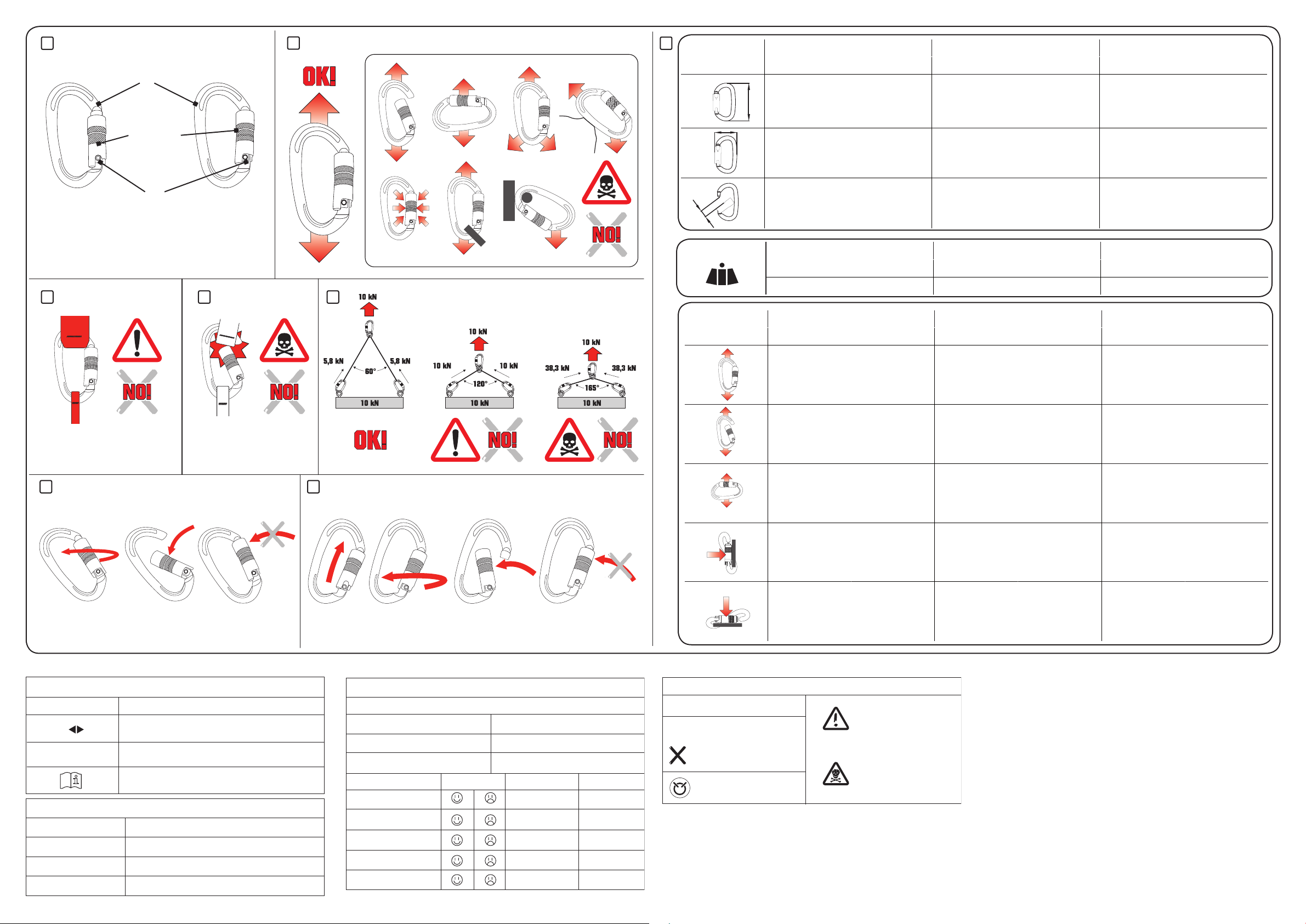
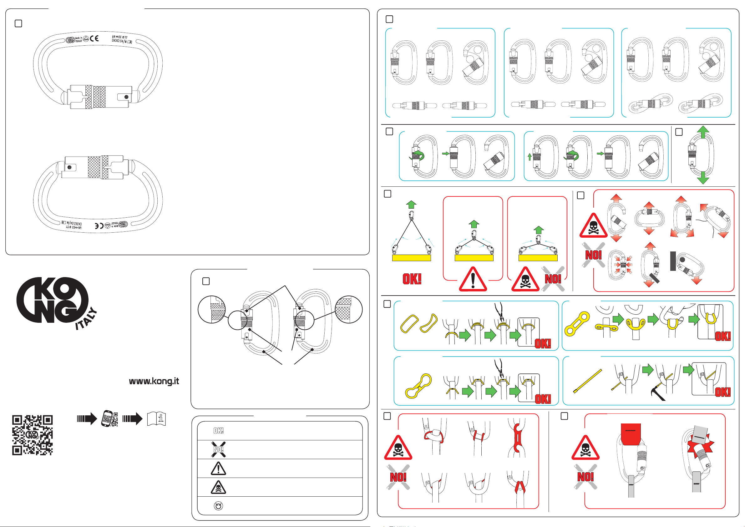
1.3 - Minimum resistance of anchoring points, on both natural and arti-
cial elements, can be at least 12 kN. The assessment of those made on
natural elements (rocks, plants, etc.) is possible only empirically, and can
therefore be performed by a competent expert, while those on articial
elements (metal, concrete, etc.) can be calculated scientically, and can
therefore be performed by qualied personnel.
1.4 – 802.100 BACK-UP ANSI is tested in accordance to ANSI/ASSE
Z359.15-2014. This device is inspected in accordance with the proce-
dures of the Quality System certied according to the UNI EN ISO 9001.
Warning: laboratory tests, inspections, information and norms do
not always manage to reproduce what actually happens in practice,
and so performance under real usage conditions in a natural envi-
ronment may differ, sometimes even considerably. The best infor-
mation can be gained by continual practice under the supervision
of skilled, expert, qualied individuals.
2 - WARNINGS
- It is strictly forbidden to alter and/or repair the device, only the equip-
ment manufacturer, or persons or entities authorized by the manufactur-
er, are allowed to repair the equipment.
- Before use make sure that the device is suitable for the purpose: only
the techniques that are not crossed out are permitted, any other use is
considered improper and therefore potentially dangerous.
- Verify combinations of components or sub-systems, or both, they have
not to affect or interfere with the safe function of each other.
- Improper use, deformation, falls, wear, contact with chemical substanc-
es, chemical contamination, exposure to direct sunlight (UV degrada-
tion), heat sources and ames, exposure to temperatures below -20°F
or higher than +120°F, are some examples of other causes that may
produce a harmful effect, or reduce, limit or end the life of the device.
- We strongly suggest using the device personally in order to continuous-
ly monitor the degree of protection and efciency.
- At low temperatures, the presence of moisture can form ice that, on
textile devices, can reduce exibility and increases the risk of cutting and
abrasion.
- Pay particular attention when using the equipment around moving ma-
chinery and electrical hazards, sharp edges or abrasive surfaces.
3 – MAINTENANCE AND STORAGE
- Equipment which is in need of, or scheduled for maintenance shall be
tagged as “unusable” and removed from service.
- Maintenance and storage of equipment shall be conducted by the user’s
organization, consists of washing in warm drinking water (90°F), possibly
with the addition of neutral detergent. Rinse and, without spinning, leave
it to dry without leaving it in the direct sunlight.
- In addition, if necessary disinfect the device, soaking it in warm water
containing 1% of sodium hypochlorite (bleach). Rinse with drinking water
and, without spinning, leave it to dry without leaving it in the direct sun-
light. Avoid sterilising textile devices in an autoclave.
- Equipment shall be stored in a manner as to preclude damage from environ-
ment: maintain temperature between 5-30°C (40-85 °F) and relative humidity
between 40-90%, avoid exposure to light, UV, sharp edges, excessive mois-
ture, oil, chemicals and their vapours or other degrading elements.
- Exceptional maintenance and storage issues, which may arise due to un-
usual conditions of use, shall be addressed with the manufacturer.
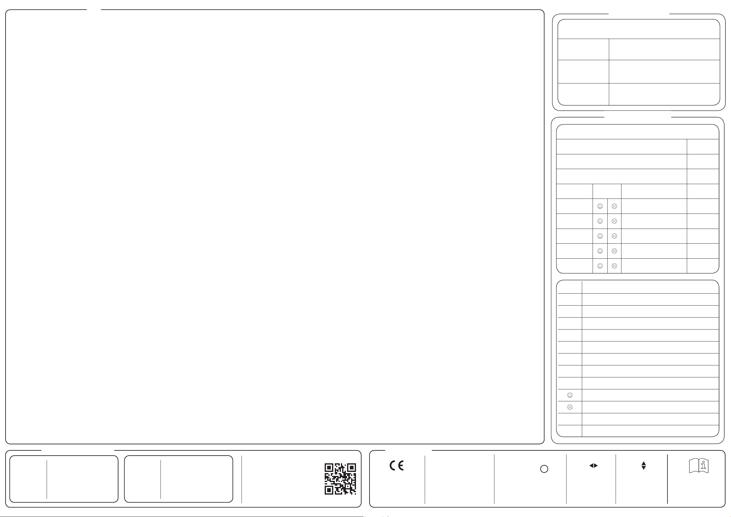
4 – INSPECTION
Inspection criteria for the equipment shall be set by the user’s organization.
Such criteria for the equipment shall equal or exceed the criteria established
by ANSI/ASSE Z359.2:13 or the manufacturer’s instructions, whichever is
greater. The outcome of these periodic inspections shall be recorded on the
device’s inspection chart or a designated register. When inspection reveals
defects in, damage to, or inadequate maintenance of equipment, the equip-
ment shall be permanently removed from service or undergo adequate cor-
rective maintenance, by the original equipment manufacturer or their desig-
nate, before return to service. In addition to the inspection requirements set
forth in the manufacturer’s instructions, the equipment shall be inspected by
the user before and after using the device and additionally by a competent
person, other than the user, at interval of no more than one year for:
- absence or illegibility of markings,
- absence of any elements affecting the equipment form, t or function,
- evidence of broken stitches xed to load indicators,
- evidence of defects in or damage to hardware elements including crack,
sharp edges, deformation, corrosion, chemical attack, excessive heating, al-
teration and excessive wear,
- evidence of defects in or damage to strap or ropes including fraying, un-
splicing, unlaying, kinking, knotting, roping, broken or pulled stitches, exces-
sive elongation, chemical attack, excessive soiling, abrasion, alteration, ex-
cessive aging and excessive wear.
5 - DEVICE LIFE
Lifetime of metallic equipment is indenable, theoretically unlimited, while
those in textile, synthetic or plastic is 10 years from the date of production,
under the following conditions:
- the operating procedures comply with point 2,
- maintenance and storage are carried out as described in point 3,
- the outcomes of pre- and post-use checks and periodical inspections are
positive,
- the equipment is used correctly, not exceeding ¼ of the marked load.
Any equipment that do not pass the pre-use, post-use and periodic inspec-
tions shall be discarded.
6 – LEGAL OBLIGATIONS
Professional and recreational activities are often regulated by specic nation-
al or governmental laws that may impose specic limits and/or requirements
for the personal fall arrest systems, which includes this device in their compo-
nents. The user is obliged to know and apply these laws, which may in some
cases impose obligations different from those contained in this information.
7 – GUARANTEE
The manufacturer guarantees that the device complies with regulations in
force at the time of production. The guarantee covering faults is limited to pro-
duction defects and raw materials. It does not include wear and tear, oxida-
tion, damages caused by improper use and/or during competition, incorrect
maintenance, transport, conservation, storage, etc. The guarantee becomes
void as soon as the device is modied or tampered with. The validity corre-
sponds to the legal guarantee of the country where the device was sold by
the manufacturer, with effect from the date of sale. After this period no claim
can be made against the manufacturer. Any request for repair or replacement
under this warranty shall be accompanied by a proof of purchase. If the de-
fect is accepted, the manufacturer, at its sole discretion, will repair, replace or
refund the device. Under no circumstances does the manufacturer’s liability
extend beyond the invoice price of the device.
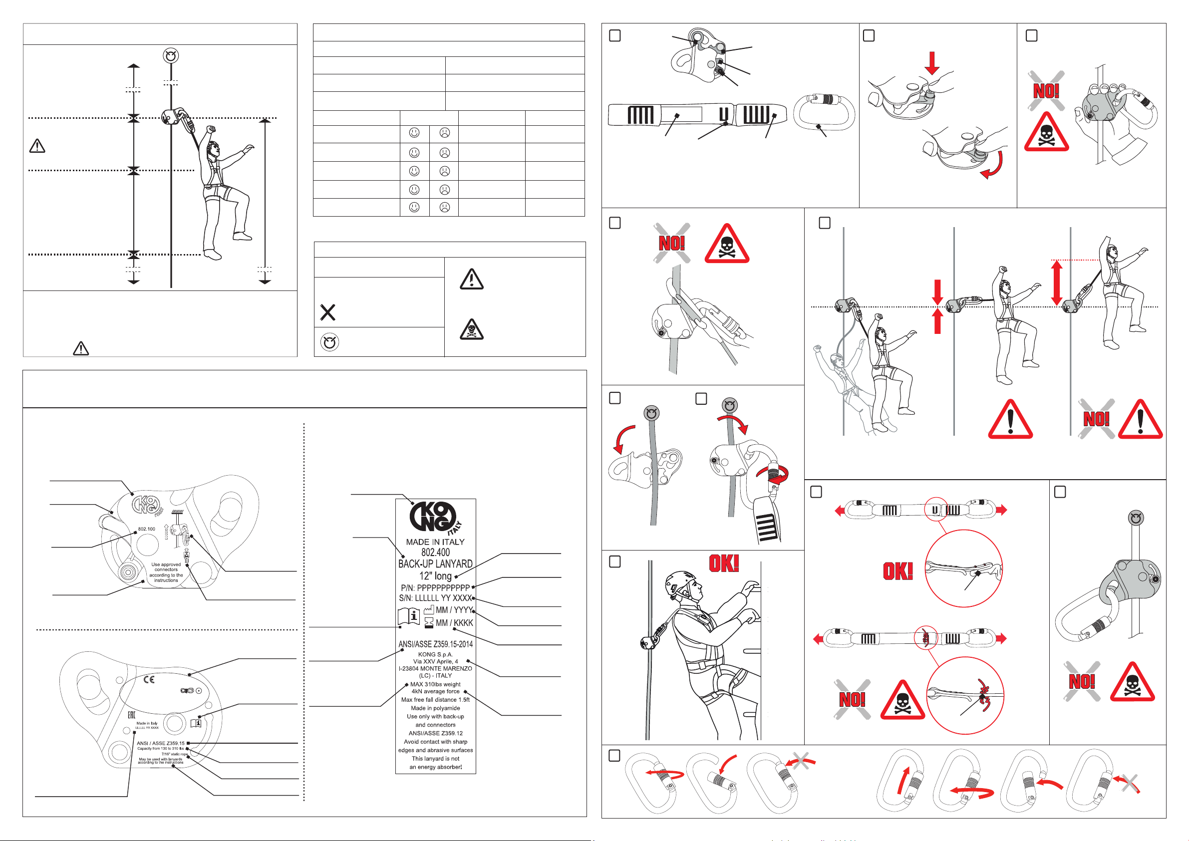
8 – USE INFORMATION
802.100 BACK-UP ANSI is a fall arrestor device that travels on a lifeline
and will automatically engage and lock onto the lifeline in the event of a fall,
arresting the user.
Important, this device comply with ANSI/ASSE Z359.15 when used:
- in «FREE MODE»,
- in the capacity range of minimum 130 lbs and maximum 310 lbs,
- with 7/16” polyester static ropes complying to CI 1201 and NFPA
1983:2012 T,
- with optional use of a lanyard:
- Non-Integral Lanyards: 802.400 Kong Backup Lanyard,
- Any Energy Absorbing Lanyards meeting the requirements
of ANSI/ASSE Z359.13.
Warning: humidity, snow, ice, mud, dirt, etc. greatly reduce (up to nulli-
fying) the performances of the devices.
8.1 – Nomenclature of the parts
Fig. 1 – (A) Lock device – (B) “Free mode” / “Lock mode” selection lever – (C)
Connector – (D) Lanyard with Load indicator (E) - (F) Label.
8.2 – Use in a fall arrest system
For the sake of safety in case of risk of falls from a height, it is essential to:
- assess the risks and make sure that the whole system, where this device is
only a component, is reliable and safe,
- prepare a rescue plan to deal with any emergencies possibly arising while
the device is being used,
- have the means at hands to implement the rescue plan,
- make sure that the anchoring device or the anchoring point is always posi-
tioned as high up as possible, and that work is done in such way as to reduce
potential falls and relevant heights to a minimum,
- in order to avoid all possible problems (e.g. ground, material rubbing against
the rock face, abrasions, etc..), carefully assess the free height under the
user (clearance). Examples of main factors can be: height of a potential fall,
Full Body Harness Stretch (Hs), rope paid out, the length of any attachment
element extender, the stretch in any energy dissipaters or absorbers, the
height of the user and the “pendulum” effect.
Important: in a system for protection against falling from heights, it is obliga-
tory to use a complete harness in compliance with current regulations.
8.3 – Function modes
Select the function mode before inserting the device on the rope, according
to the intended purpose:
- “FREE MODE”: the device is free to move in both directions.
- “LOCK MODE”: the device slides in one direction only (upwards).
The selection between “FREE MODE” and “LOCK MODE” is made by mov-
ing the lever (B) tted with a locking button:
- push down the button,
- move the lever (B) to the desired position (g.2),
- check that the button returns in position and locks the lever movement.
Warning, DANGER OF DEATH:
- the device blocks if the load is applied to the connector only, therefore
never load it in any other way (e.g. g. 3 and 4) because it will slide
along the lifeline,
- do not manipulate the device or hold the fall arrester body or lever,
instead move it up by the lanyard.
- the device shall be kept equal to or above the height of the harness
attachment point (g. 5),
- this device must be used only with the following connector series
attached directly to the eyelet: 412 OVALONE, 414 OVALONE DNA, 512
OVALONE SS.
8.4 – Connection of the device
With the device in front of you, in the same position as gure 6:
- choose function mode “FREE MODE” as in point 8.3,
- open the device by rotating anti-clockwise the revolving face,
- insert the device on the lifeline,
- close the device by rotating clockwise the revolving face,
- insert the connector (C) into the eyelet of the “BACK-UP”, hook it up to the
attachment point of the full body harness and let the gate of the connector
close.
Important:
- keep the device as high as possible above the user to reduce slippage (g.
7),
- the unstitching of the load indicator (E) means that the lanyard (D) has been
loaded with a force of approx. 4 kN (g. 8), in such event replace the whole
device.
Warning:
- do not connect the device to:
- the lifeline in any other way, (e.g. g. 9): risk of death!
- types of lifeline and/or lanyard different from what specied, be-
cause the device performance may differ from the performances
specied in the standard,
- attachment points of full body harnesses not compatible with fall
arrest systems,
- more than one lifeline,
- more than one user.
- when positioning the device, make sure that:
- during use, the user will not be positioned on an unstable
surface, ne grain material such as sand or coal,
- anchor points of the lifeline are placed above the user,
- the lifeline between anchor point and user is not loose.
9 - CHECKS BEFORE AND AFTER USE
Check and make sure that:
- the device:
- is suitable for the intended use;
- is not out of shape and does not show signs of cracks or wear;
- its inner levers and springs work freely,
- its selection lever is working as described in point 8.3,
- the points where the rope passes through are free from mud,
sand, etc. and that there are no lubricant substances.
- the connector (C) is working correctly, in particular check that the gate
locking device works as described in g. 10,
- the lifeline and the lanyard (D) do not show any signs of damaged
threads, stiffening, variations of diameter, cuts, wear or seams coming
apart. Be careful of cut or loose threads!
- the load indicator (E) is unbroken.
Before use, on each occasion check that the device holds correctly by
putting your weight on it, in a position that is completely safe.
10 – CONFORMITY
The compliance of conformity has been supplied by the accredited labo-
ratory following the EN ISO 17025: n. 1539 DOLOMITICERT scarl - zona
industriale Villanova – 32013 Longarone (BL) – Italia.
ZZV05512 rev.1
KONG s.p.a.
Via XXV Aprile, 4 - (zona industriale)
I - 23804 MONTE MARENZO (LC) - ITALY
BACK-UP
802.100
ANSI USE