manuals.online logo
Brands
  1. Home
  2. •
  3. Brands
  4. •
  5. Krick
  6. •
  7. Toy
  8. •
  9. Krick 20360 Instruction Manual

Krick 20360 Instruction Manual

Stand Juli 2014 Seite 1 ©Krick Modelltechnik Knittlingen
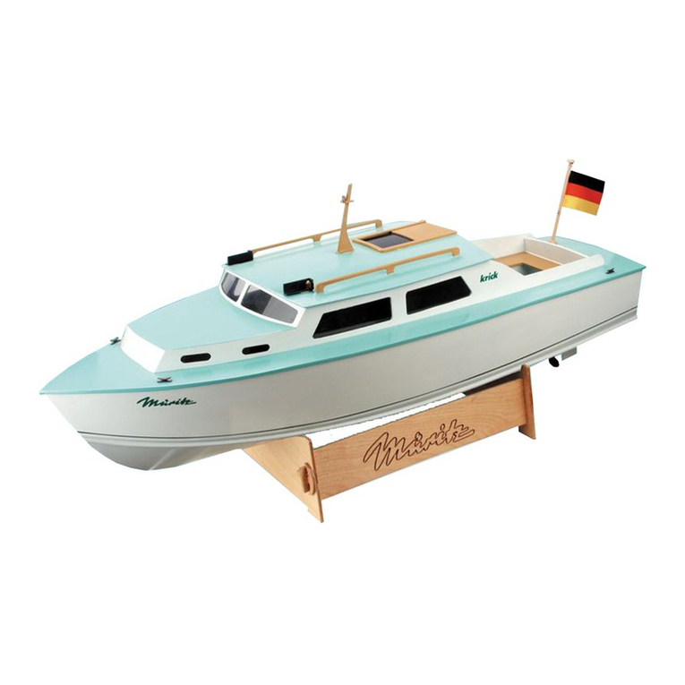
Building Instructions Policeboat WSP 47
Order-No. 20360
Congratulations for buying this model kit of the
police boat WSP 47. This model is mainly de-
signed for the beginner, but is also a very in-
teresting kit for more experienced modellers as
a basis for own ideas.
For building this model you should have follow-
ing glues, fillers and paints:
- Superglue Krick ruck-zuck 20g thin (80491)
- Superglue Krick ruck-zuck 20g medium
(80495)
- 5min-Epoxy glue 100g (80479)
- wood glue UHU Holz waterresistant 75g
(48515)
- 2-component glue UHU-Plus acrylit 30g
(48315)
- Filler Micro-Fill white 295 ml (80480)
- Primer (Lord Nelson 80110)
- Clear Varnish for stairs, doors, (80112)
- paint spray blue (320053), light grey (Primer
and for deck), and white (320010)
-lacquer red, grey, silver and black for fittings
Following tools are recommended for building
WSP 47
- modelling knife (416002)
- hand drill (473841)
- sandpaper files (491016)
- sanding block (490080)
- sand paper of grane 180, 320, 400 and 600
(Set 490190)
- round file ca. Ø 6 mm
- drills Ø 1 mm, 1,5 mm, 2 mm, 3 mm, 4 mm,
6,5 mm
- wet sand paper 400 und 600 for filler, primer
and paints
- side cutter (455550)
When painting use masking tape to cover the
areas not to be painted. Use a 3 mm wide
tape should be used for the water line.
For running and radio control you should have
following parts:
- 2 channel radio control including one Servo
- electronic speed control 20 A, forward/back
including BEC
- battery pack 7,2V NiCd, NiMH or lead battery
6V/1,1 Ah
- charger 220V AC or 12V DC
Stand Juli 2014 Seite 2 ©Krick Modelltechnik Knittlingen
If you like to install the special features such as
-rotating radar
-Lighting
-And working fire monitor,
You will also need following items:
-Pump ( 65150)
-Mini lights
-Geared motor 1:300 (42203)
If you wish to install these items you will also
need a 4/6 radio control
Pictures in the following instruction should
help to make the building of the model as easy
as possible.
For identifying the laser cut parts in the
wooden sheets, there is a drawing at the end
of this instruction book. Before you start build-
ing you should identify all wooden parts and
mark the part nos. on the part with a soft pen-
cil. During the building process you should
carefully cut out the required parts only. Cut at
the tabs with a sharp knife.
Starting this hobby is much easier, if you have
an experienced modeller to call on. Often the
best way is to join a local model boat club.
We wish you good fun and success with build-
ing this nice model.
I. BOAT STAND and HULL
1. Boat stand
First build the boat stand with parts 2, 3 and 4.
After the glue is dry carefully sand and varnish
the stand several times. As you will later place
your wet model on the stand, it is important to
have this water resistant. To protect the model
you can use some pieces of foam tape on the
stand parts which will come in contact with the
hull.
2. Hull
Mark the positions of the rudder tube and of
the prop shaft on the hull (1). First measure the
centre line of the hull and mark. Then mark the
rudder tube position 35 mm from the stern of
the hull. Mark the position of the prop shaft 15
mm down from keel end.
Now drill the holes for prop shaft and rudder
tube.
First use a small drill of about 2 – 3 mm and
then enlarge to the correct size – rudder tube 4
mm and prop shaft tube 6 mm. You can do this
best with a round file to stop the hull from split-
ting.
3. Deck
Now fit the deck to the inside of the hull (5). At
the area of the bow it is necessary to chamfer
the deck so it is a snug fit and sits in the hull
without any pressure being applied.
2 3
4
4
1
5
chamfer in the front
area
Stand Juli 2014 Seite 3 ©Krick Modelltechnik Knittlingen
Now place the deck into the hull and mark a
line on the sides 2 to 3 mm over deck level.
Cut the hull down only until to this line with a
sharp knife or strong scissors.
Now place strips (6 to 9) on the underside of
the deck around the inner cut out. Place a
weight on the deck until the glue is dry so the
deck cannot twist.
Now the coaming strips (10 to 13) have to be
glued vertical to the strips so that they are flush
on the underside and protruding on the upper
side. The superstructure will sit over this so
that no water can ingress the hull.
4. Rudder Tube
Glue the rudder tube (14 ) to the 2 supports
(15). Use medium or thick super glue or UHU
plus acrylit glue for this. Place the parts onto a
flat surface. Once dry place the assembly into
the hull along with the third support. Glue this
support to the rudder tube, but do not yet glue
into the hull.
5. Rudder
Make the rudder from parts 160 – 163. First
glue parts 162 and 161 to each other.
5
1
5 6
5
5
10 to 13
15
14
162 161
163
160
Stand Juli 2014 Seite 4 ©Krick Modelltechnik Knittlingen
Then glue these inner parts onto one outer
side (160) that a gap remains for the rudder
shaft.
Roughen well the rudder shaft on the area,
which will be glued into the rudder.
Now glue in the rudder shaft with Uhu Acrylit
and the second outer plate (160) on top.
Now make a profile on the rudder, sharp at the
end and round at the front.
6. Motor Mount
Make the motor mount / Servo tray assembly
from parts 16-17 and 18 and glue. You will find
on the laser sheets two different motor mounts.
First compare with the motor, which motor
mount is the correct one for your motor.
For 400 motors there are parts on sheet 2.For
500/600 motors on sheet 3.
Now make the battery and receiver tray with
parts 19, 20 and 21.
16
17
18
19
20 20
21
21
Stand Juli 2014 Seite 5 ©Krick Modelltechnik Knittlingen
All parts for the inside of the hull should be
ready now. Please varnish them 2 to 3 times
and sand between each application so that
they are water proofed. Also the deck should
be varnished on the underside.
Place the Servo temporarily into the tray and
drill the holes with 1.5 mm drill for the Servo
screws.
7. Preparation of the Motor
Solder on the motor the suppression capaci-
tors 103 (10nf) to the connections and to the
motor housing as shown. Sand before solder-
ing, to ensure a good connection for the solder.
Then solder the third capacitor 473 (47 nf)
between the two motor connections. Place
insulation tube on the ends before soldering.
Now solder motor wires to the connections.
After that you can assemble the motor to the
motor frame.
8. Fitting out the Hull
Push the prop shaft through the hole in the hull
and fit the motor on the motor mount. Now
attach the brass coupling between Motor and
prop shaft with grub screws M3. Please check
that there is a gap of about 1 mm between
motor housing and coupling.
Now align the motor together with motor
mount, prop shaft and tube inside the hull. The
whole setup should be placed in the centred of
the hull so that the tube of the prop shaft is
protruding 25 mm out of the hull.
Before proceeding double check that the as-
sembly is placed in the centre of the hull.
Servo
Drill
Stand Juli 2014 Seite 6 ©Krick Modelltechnik Knittlingen
Now fix the tube and the motor mount with
UHU Plus Acrylit inside the hull and fill the end
of the hull around the shaft with glue so that it
is water tight.
After the glue is set, you can also fix the rudder
shaft and the battery platform in the same way.
9. Gluing the Deck
Now all interior is placed correctly inside the
hull. So it is time to fix the deck permanently on
the hull. Fix the deck with adhesive tape to the
hull in a way, that the side walls of the hull are
pressed equally to the deck without getting
waves.
Fix the deck at several points with thin super-
glue. After that you can fix the deck complete
with medium superglue You can use an activa-
tor spray to shorten the drying process.
After the glue is dry you should sand the over-
lying border of the hull down to deck level. If
gaps appear, you can fill them with a wood
filler.
Stand Juli 2014 Seite 7 ©Krick Modelltechnik Knittlingen
II SUPERSTRUCTURE
1. Cabin
For the first step of building the superstructure
you will need parts 32, 33, 34 und 40.
Now draw the outline of the windows to the
glazing material of PVC (100). Make them
slightly oversize to allow for gluing to the
frames.
Dry fit the parts first. If necessary sand the
slots or tenons for a perfect fit. Now first glue
the side walls to the frame and back wall.
When the gluing points are dry you can glue
the bar (40) in place.
2. Cabin Roof Front
Now place the front roof (35) with its cut out
corners between the two side walls and glue
only at the cut outs.
Fix the roof at its cut outs with superglue.
When the glue is dry, bend the side to the
curve of the roof and fix with superglue.
When the glue is dry, do the same on the other
side. After this apply glue from inside, and then
fix with clamps.
Now fit the front part (37) to the superstructure.
The upper edge needs to be sanded at an
angle to fit correctly.
32
34
33
32
40
35
Stand Juli 2014 Seite 8 ©Krick Modelltechnik Knittlingen
Now sand the flush the overlaying ends.
3. Front Windows
In the next step the front windows 38 and 39
will be fitted..
First bevel the lower edge of the centre part
about 45 degrees.
The front windows at the side have to be bev-
elled at the lower edge and at the edge to the
centre window.
In the next step you have to sand the contour
of the main roof on top of the front windows in
the same way as the contours of the frame and
back wall. Then sand the side edges flush with
the side walls.
4. Cockpit
At this stage you will make the cockpit. For this
you will need parts 49, 50 and 51.
37
sand
to the re-
quired an-
gle.
38 3939
sand to the
required angle
angular
sand to the
required
angle
49
50
51
50
Stand Juli 2014 Seite 9 ©Krick Modelltechnik Knittlingen
Now glue the cockpit to the superstructure.
Then fit the hand rail 52.
5. Roof
The last step for the superstructure starts with
gluing the main roof (36) on top.
Now the body shell of the superstructure is
ready.
6. Alignment to Deck
At this stage the superstructure will be placed
on the deck and the curve of the lower edge
has to be aligned with the curve of the deck.
This has to be done mainly in the front area.
For this you can mark the deck line to the su-
perstructure with a pencil, laid flat onto the
deck. Then sand the curve.
7. Mast
Prepare the mast from the two halves 41 and
42. First glue parts 42 on part 41. Take care to
get two mirrored halves.
If you are interested to light the ships lamps on
the mast with bulbs or LEDs it is recommended
to open the ends of the prepared channels for
the cables now so that the cables can be
pushed through later. For this open the bar at
52
36
42 41
Stand Juli 2014 Seite 10 ©Krick Modelltechnik Knittlingen
the bottom. At all the cable entrance places
you can file out curves with a round file and
drill the holes open later, when needed.
For the Radar file out the opening 12 mm be-
hind the upper front edge of the mast base or
drill a 4 mm hole later.
Now the two halves can be glued together.
With a 90deg square check that the mast
stands vertically.
Drill two 2mm holes at both ends of the mast
yard (45) fort he antenna base (46).
Fit the yard into the mast, both ends equal.
Now fix the yard into the mast with superglue
and both antenna bases into the yard. After the
glue is dry the yard ends can be carefully bent
to the rear.
The last step is to glue the lamp board and the
mast top onto the mast. Take car that the hole
of the plate and the mast opening are at the
same place.
Now the mast can be sanded and glued to the
roof.
drill
Stand Juli 2014 Seite 11 ©Krick Modelltechnik Knittlingen
7. Painting
Now the superstructure can be sprayed with
filler and sanded several times and afterwards
you can use a lacquer for the finish in the
wished colour.
III. Details
In the following steps the accessories will be
made.
Door, rail, radar, anchor winch, bow reel,
stairs, ladder.
1. Door
Sand and varnish the door (62) and glue it to
the painted back wall. Then bend the door
handle from brass wire 1,5x15 mm (108) and
slide a brass tube 2x1,5x7 mm (104) over it for
a thicker handle.
2.Rail
Sand the stanchions (140) at their lasered
edges, to allow the paint to adhere.
Place the stanchions into the cut outs of the
deck, but don´t glue them yet.
Slide the rail wire through the holes and bend it
in the correct way at the ends. Fix the wire with
superglue to the stanchions. For painting you
can now take the Rail off.
3. Radar
Now make the radar and possibly the gear for
it from parts 63 to 75.
62
108
140
Glue here
44
43
Stand Juli 2014 Seite 12 ©Krick Modelltechnik Knittlingen
Chamfer the edges of parts 65 and 67 all
around.
Now glue parts 63 to 76 all together, aligned by
the hole in the centre.
The next step is to fit the brass tube into the
radar housing as a bearing for the radar shaft
with superglue or epoxi. At the top the brass
tube should protrude about half a millimetre.
Sand the rear edge of the radar bar 68 round.
Glue the radar shaft 70 into the bar with super-
glue.
If you wish to make the radar working, you also
have to do the following steps and order the
optional geared motor.
Make the motor mount from parts 72 and 73
and prepare the slot parts 74.
Fix the motor with screws to the motor mount.
Then fit the coupling tube 71 onto the shaft of
the motor.
71
75
67
66
65 64
63
69
70
72
73
74
68
67
66
65
64
63
67
65
Sand this edge round
Stand Juli 2014 Seite 13 ©Krick Modelltechnik Knittlingen
For fixation of the slotted supports to the sides
of the cabin place slide the radar shaft (70) into
the coupling tube (71) and align the motor
mount inside the cabin. Then fix the supports
(74) at the side walls of the cabin with super-
glue.
Take out the motor mount and finally glue the
supports (74).
4. Anchor Winch
Build up the anchor winch from parts 76, 77,
78, 79, 80 and 81.
Glue the main part (76) to the sides (77).
Then place and glue the base (78).
Glue the motor plate (79) to the right side as
shown.
Now the wooden parts should be filled sanded
and painted white or grey.
Now the wooden parts should be painted with
sanding sealer and sanded. Afterwards place the
motor (80) and capstan (81) with super glue.
77
76
77
79
78
8081
75
74
74
Stand Juli 2014 Seite 14 ©Krick Modelltechnik Knittlingen
10. Bow Reel
Identify parts 83, 84, 85 and 86.
Glue the sides 83 to the main piece 84.
After sanding and painting place reel and pin
and fix the pin with a drop of medium super
glue. If necessary you have to sand down the
reel on both sides to fit between the two sides.
11. Stairs
Glue the parts 59 and 60 to build the stairs.
Then varnish and sand the assembly
7. Assembly of ladders
Make the ladders from parts 115, 116, 118 and
119. Glue the strips on top and bottom of the
laser cut ladder. After the glue is dry carefully
sand the edges flush.
8. Navigation light boards
Make the boards from parts 111, 112 und 113.
9. life saver supports
Make the life saver supports from parts 109
und 110. Sand the lasered edges very carefully
before painting.
84 83
83
85
86
60
59
59 60
60
112
111
113
109
110
116
11
5
119
11
8
Stand Juli 2014 Seite 15 ©Krick Modelltechnik Knittlingen
10. Firemonitor
Now build the fire monitor from parts 121, 122,
123, 124, 125, 126, 127, 128, 129, 130, 131
and 132.
First build the base and the upper angle.
Next glue the bottom tube into the base.
Now fit brass parts 128 und 129 together.
Press jet 128 into tube 129.
Now glue the upper angle to the base.
After painting slide the tube through the upper
angle and slide it into the black silicon tube
134. Then glue the tube into the upper angle.
At last glue the axle 131 into the hand wheel
132 and fix it to the monitor.
1
30
128 129
121
122
124
123
12
5
12
6
128
12
9
132
130
134
131
132
Stand Juli 2014 Seite 16 ©Krick Modelltechnik Knittlingen
11. Lamps
Paint and glue the lamps from parts 146, 147,
148 and 153. Make 5 Lamps with the base
146 uand 2 Lamps for mast yard with the
round base 153.
12. Blue lamp
Paint and glue the blue light from parts 148,
153, 154 and 155.
13. Tow bollard
Combine parts 134, 135, 136 and 137 to the
tow bollard.
Drill two holes 4 mm into the supports 135.
Then glue the parts together
148
147
146 153
148
154
146 155
137 136
135
138
Stand Juli 2014 Seite 17 ©Krick Modelltechnik Knittlingen
14. Miscellaneous fittings
Finally fit the rest of fittings to deck and super-
structure. Please note the following pictures as
a reference.
143
93
139
120
Stand Juli 2014 Seite 18 ©Krick Modelltechnik Knittlingen
14. GPS antenna
Make the GPS antenna from parts 149.1 to
149.5.
Glue the parts together concerning there size.
Then sand the glued parts round to a hemi-
sphere.
Stickers and letters
The letters are cut from weatherproof self ad-
hesive foil. Cut out the full word from the foil
and then tear off the rest material around the
letters. To leave the letters in exactly the same
distance to each other, when removing the
support material, glue some tape over the let-
ters, which you can tear off later. The letters do
not need to be covered 100%. It is advisable to
leave the upper or lower edges of the letters
free for exact positioning of the letters. Then
carefully tear off the support material and place
the letters exactly into place. Finally remove
the tape carefully from the letters.
Cut out the emblem exactly and glue it to each
side of the cabin.
IV. Installation of the pump
The pump to make the fire monitor working is
available as an extra accessory.
Drill a 4 mm hole into the hull directly behind
the propeller for adding the brass tube 159 and
glue this with Uhu Acrylit into the hull.
150
151
156
149
152
149.5
.4
.3
.2
.1
Stand Juli 2014 Seite 19 ©Krick Modelltechnik Knittlingen
Make from 3 mm rest plywood two triangular
pieces with 5 mm hole inside to fix the water
tube along the corner in the hull to the pump.
Adapt the triangular pieces to the shape of the
hull and glue them with Uhu Acrylit.
The pump will be placed on the RC board in
front of the battery box.
Fit the input and output tube (from the monitor)
to the pump
For the control of the pump you will need an
extra electronic switch for use at one channel
of the radio control.
V. Radio Control
For running your model on the water, you will
need a 2 channel radio control system with one
servo.
For the control of the motor you will need an
electronic speed control with forward and re-
verse control. This should have a constant
capacity of minimum 20 Ampere and should be
equipped with BEC.
The steering servo needs to be fitted to the
motor mount. Before assembly you should
check it is standing in the neutral position, as
adjusting later will be difficult.
For steering the rudder first the rudder lever
(97) needs to be fixed to the rudder shaft and
combined with the steering rod, made of parts
98, 99 and 107, then aligned. Please check
that the rudder turns to the left when the radio
command is left. If not you should be able to
revers the servo with the channel reversing
switch on your transmitter.
Fix the receiver to the front of the battery with
double sided adhesive tape.
The electronic speed control should also be
fixed with double adhesive tape to one side of
the motor mount. It should be positioned so
that switches or potentiometers can easily be
adjusted.
Join the cables from the motor with the cables
from the speed control in the shortest possible
way and solder together.
Please note the instruction of the speed control
for the adjusting and use of it. If a BEC is sup-
plied wit the speed control, you will not need
an extra battery for your receiver.
VI. Final Work
When all installation is done, please make a
final check all over your model. All joints and
installations should be checked for their clear
and stabile fit and if necessary corrected. Also
please make a test of the trim of the model in
the bath tub before you go to a lake for the first
run. The trim normally needs to be adjusted
with some weights of lead.
Before the first run on the water please make a
range check of your radio. For this place the
model onto the stand. Switch on the transmitter
and receiver, but leave the antenna of the
transmitter short. Now let the motor run full
speed and use the rudder lever slowly but
constantly left and right. If the rudder also
moves without any tremor, your radio works
well.
159
Stand Juli 2014 Seite 20 ©Krick Modelltechnik Knittlingen
Now the first sail can start. We wish you all the
best with your „WSP 47“.
For any questions and help you can contact
us.
Klaus Krick Modelltechnik,
Postfach 1138, 75434 Knittlingen
Tel. 07043/9351-0, Fax 07043/31838

This manual suits for next models

2

Other Krick Toy manuals

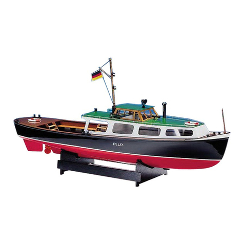
Krick Katja Instruction Manual

Krick

Krick Katja Instruction Manual

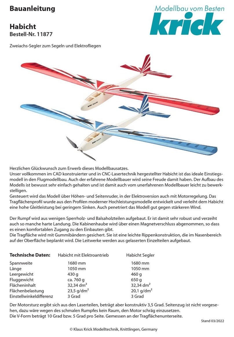
Krick Habicht User manual

Krick

Krick Habicht User manual

Krick 20300 Instruction Manual

Krick

Krick 20300 Instruction Manual

Krick Lisa M. Instruction Manual

Krick

Krick Lisa M. Instruction Manual

Krick Victoria User manual

Krick

Krick Victoria User manual

Krick 20310 User manual

Krick

Krick 20310 User manual

Krick Nordstrand Instruction Manual

Krick

Krick Nordstrand Instruction Manual

Krick COMTESSE User manual

Krick

Krick COMTESSE User manual

Krick Muritz Instruction Manual

Krick

Krick Muritz Instruction Manual

Krick Anna User manual

Krick

Krick Anna User manual

Krick 65312 Instruction Manual

Krick

Krick 65312 Instruction Manual

Krick Klemm L25-D User manual

Krick

Krick Klemm L25-D User manual

Krick Sea Cruiser ARIADNE Instruction Manual

Krick

Krick Sea Cruiser ARIADNE Instruction Manual

Krick Ro-marin Katja Instruction Manual

Krick

Krick Ro-marin Katja Instruction Manual

Krick ANTARES User manual

Krick

Krick ANTARES User manual

Krick Ro Marin ro1539 Instruction Manual

Krick

Krick Ro Marin ro1539 Instruction Manual

Krick Borkum Island Supporter Instruction Manual

Krick

Krick Borkum Island Supporter Instruction Manual

Krick 20320 Instruction Manual

Krick

Krick 20320 Instruction Manual

Krick Fishing Cutter Antje Instruction Manual

Krick

Krick Fishing Cutter Antje Instruction Manual

Krick ro1160 User manual

Krick

Krick ro1160 User manual

Krick ro marin Neptun Instruction Manual

Krick

Krick ro marin Neptun Instruction Manual

Popular Toy manuals by other brands

Eduard Jagdpanther G2 Assembly instructions

Eduard

Eduard Jagdpanther G2 Assembly instructions

ELE RC RQ-7 manual

ELE RC

ELE RC RQ-7 manual

PIKO BR E63 Instructions for use

PIKO

PIKO BR E63 Instructions for use

furReal WALKALOTS E5309 instructions

furReal

furReal WALKALOTS E5309 instructions

PARKZONE Ka-8 instruction manual

PARKZONE

PARKZONE Ka-8 instruction manual

Mattel Barbie K9235 instructions

Mattel

Mattel Barbie K9235 instructions

Super Flying Model Sbach 342 Thunderblot instruction manual

Super Flying Model

Super Flying Model Sbach 342 Thunderblot instruction manual

Arizona Hansa Brandenberg W.29 Assembly and historical information

Arizona

Arizona Hansa Brandenberg W.29 Assembly and historical information

Fisher-Price T4949 instructions

Fisher-Price

Fisher-Price T4949 instructions

Phoenix Model PA-18 Super Cub instruction manual

Phoenix Model

Phoenix Model PA-18 Super Cub instruction manual

TA HORIZONS STOL X Assembly & instruction manual

TA HORIZONS

TA HORIZONS STOL X Assembly & instruction manual

REVELL F-4 C/D Phantom II Assembly manual

REVELL

REVELL F-4 C/D Phantom II Assembly manual

Trix Minitrix BR 110 manual

Trix

Trix Minitrix BR 110 manual

Chicco Baby Driver owner's manual

Chicco

Chicco Baby Driver owner's manual

Eduard B-26B-50 Invader manual

Eduard

Eduard B-26B-50 Invader manual

Trix Diesellokomotive V 140 22153 manual

Trix

Trix Diesellokomotive V 140 22153 manual

Krick Modelltechnik ro marin Happy Hunter Assembly and operating instructions

Krick Modelltechnik

Krick Modelltechnik ro marin Happy Hunter Assembly and operating instructions

Tiny Love 00478 user manual

Tiny Love

Tiny Love 00478 user manual

manuals.online logo
manuals.online logoBrands
  • About & Mission
  • Contact us
  • Privacy Policy
  • Terms and Conditions

Copyright 2025 Manuals.Online. All Rights Reserved.