Leica RM2235 User manual

Leica RM2235
Rotary Microtome
Instruction Manual
Leica RM2235
V1.1 English - 02/2005
Always keep this manual with the instrument.
Read carefully before working with the instrument.


3
Leica RM2235
The information, numerical data, notes and val-
ue judgments contained in this manual repre-
sent the current state of scientific knowledge
and state-of-the-art technology as we under-
stand it following thorough investigation in this
field.
We are under no obligation to update the
present manual periodically and on an ongoing
basis according to the latest technical develop-
ments, nor to provide our customers with addi-
tional copies, updates etc. of this manual.
For erroneous statements, drawings, technical
illustrations etc. contained in this manual we
exclude liability as far as permissible according
to the national legal system applicable in each
individual case. In particular, no liability what-
soever is accepted for any financial loss or con-
sequential damage caused by or related to
compliance with statements or other informa-
tion in this manual.
Statements, drawings, illustrations and other
information as regards contents or technical
details of the present manual are not to be con-
sidered as warranted characteristics of our
products.
These are determined only by the contract pro-
visions agreed between ourselves and our cus-
tomers.
Leica reserves the right to change technical
specifications as well as manufacturing pro-
cesses without prior notice. Only in this way is it
possible to continuously improve the technolo-
gy and manufacturing techniques used in our
products.
This document is protected under copyright
laws. Any copyrights of this document are re-
tained by Leica Microsystems Nussloch GmbH.
Any reproduction of text and illustrations (or of
any parts thereof) by means of print, photocopy,
microfiche, web cam or other methods – includ-
ing any electronic systems and media –
requires express prior permission in writing by
Leica Microsystems Nussloch GmbH.
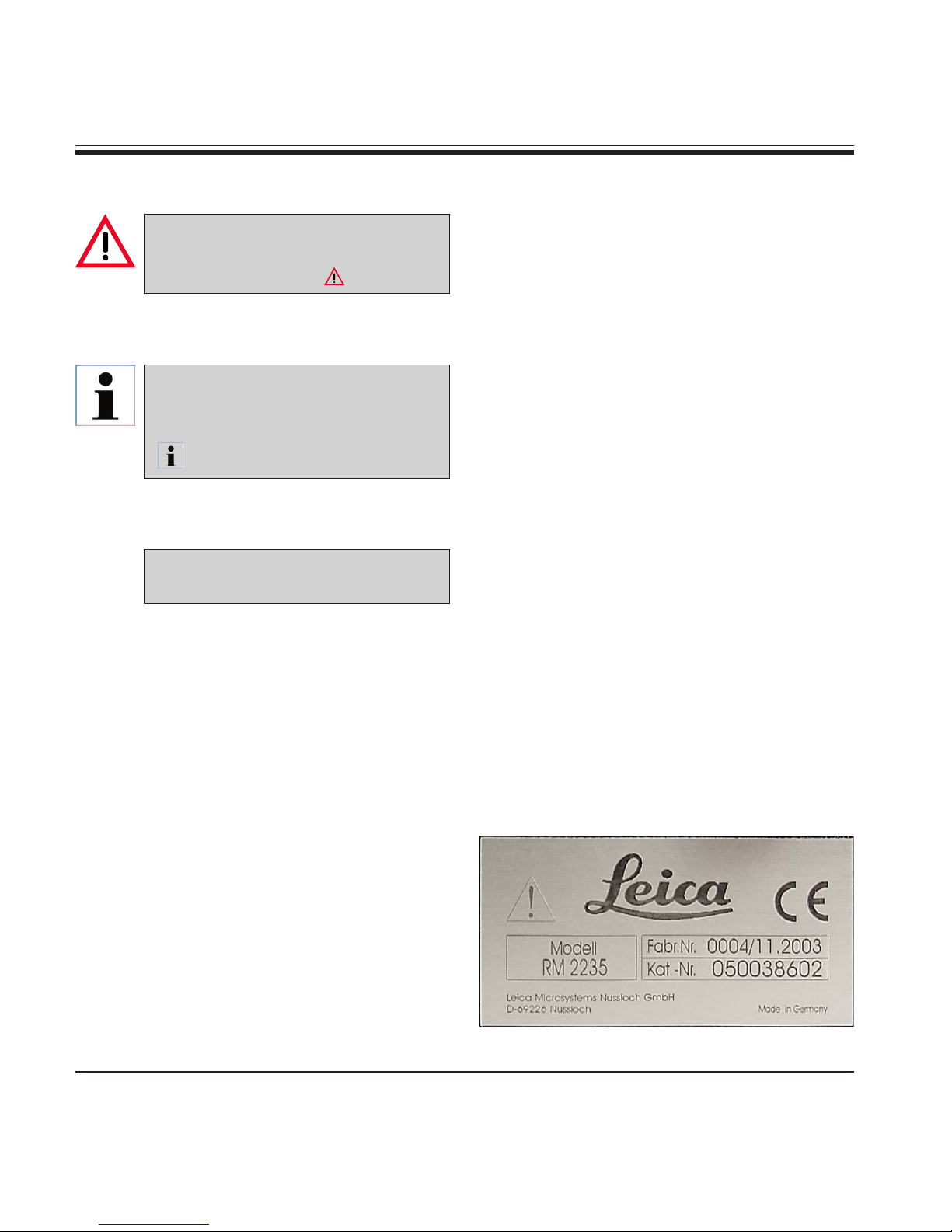
For the instrument serial number and year of
manufacture, please refer to the name plate at
the back of the instrument.
© Leica Microsystems Nussloch GmbH
NOTE
Published by:
Leica Microsystems Nussloch GmbH
Heidelberger Str. 17 - 19
D-69226 Nussloch
Germany
Phone: +49 (0)6224 143-0
Fax: +49 (0)6224 143-200
Internet: http://www.histo-solutions.com

4Instruction manual V 1.1 – 02/2005
Table of contents
1. Important notes ................................................................................................................................ 6
2. Safety ................................................................................................................................................. 7
2.1 Safety notes ......................................................................................................................................... 7
2.2 Warnings .............................................................................................................................................. 7
2.3 Integrated safety devices ................................................................................................................ 10
3. Instrument components and specifications ............................................................................. 12
3.1 Overview - instrument components ............................................................................................... 12
3.2 Instrument specifications ................................................................................................................ 13
3.3 Technical data ................................................................................................................................... 14
4. Startup ............................................................................................................................................. 15
4.1 Standard delivery .............................................................................................................................. 15
4.2 Installation site requirements ......................................................................................................... 15
4.3 Assembling the handwheel ............................................................................................................. 16
4.4 Inserting the universal cassette clamp ......................................................................................... 17
4.5 Inserting the knife holder ................................................................................................................. 18
5. Operation......................................................................................................................................... 19
5.1 Operating elements and their functions ........................................................................................ 19
5.1.1 Section thickness setting ................................................................................................................ 19
5.1.2 Coarse driving wheel ........................................................................................................................ 19
5.1.4 Mechanical trimming function ........................................................................................................ 20
5.1.3 Specimen retraction ......................................................................................................................... 20
5.1.5 Specimen holder with precision orientation ................................................................................ 21
5.2 Adjusting the clearance angle ........................................................................................................ 22
5.3 Fine adjustment of the mass balance ............................................................................................ 23
5.4 Clamping the specimen .................................................................................................................... 24
5.5 Clamping the knife / disposable blade ........................................................................................... 24
5.6 Sectioning .......................................................................................................................................... 25
5.7 Changing the specimen or interrupting sectioning ..................................................................... 26
5.8 Finishing daily routine ...................................................................................................................... 26
6. Optional accessories .................................................................................................................... 27
6.1 Installing the fixture for specimen clamps .................................................................................... 27
6.1.1 Non-orienting fixture f. spec. clamps ............................................................................................ 27
6.1.2 Orienting fixture f. specimen clamps .............................................................................................. 27
6.1.3 Fixture for specimen clamps with precision orientation ............................................................ 28
6.1.4 Quick-clamping system .................................................................................................................... 29

5
Leica RM2235
6.2 Specimen clamps and holders ....................................................................................................... 30
6.2.1 Standard specimen clamp ............................................................................................................... 30
6.2.2 Vee insert ........................................................................................................................................... 30
6.2.3 Foil clamp type 1 ................................................................................................................................ 31
6.2.4 Foil clamp type 2 ................................................................................................................................ 32
6.2.5 Universal cassette clamp ................................................................................................................ 32
6.2.6 Super Mega cassette cla mp .......................................................................................................... 33
6.2.7 Holder for round specimens ............................................................................................................ 34
6.3 Knife holder base and knife holder ................................................................................................ 35
6.3.1 Knife holder base, without lateral movement feature ................................................................. 35
6.3.2 Knife holder E/E-TC ........................................................................................................................... 36
6.3.3 Knife holder N/NZ ............................................................................................................................. 38
6.4 Section waste tray ............................................................................................................................ 40
6.5 Backlighting ....................................................................................................................................... 40
6.7 Freezer pack ...................................................................................................................................... 41
6.6 Tray ..................................................................................................................................................... 41
6.8 Ordering information ........................................................................................................................ 42
7. Trouble shooting ............................................................................................................................ 44
7.1 Possible faults ....................................................................................................................................... 44
7.2 Instrument malfunctions ...................................................................................................................... 44
8. Cleaning and maintenance .......................................................................................................... 45
8.1 Cleaning the instrument ................................................................................................................... 45
8.2 Maintenance instructions ............................................................................................................... 47
8.3 Lubricating the instrument .............................................................................................................. 48
9. Warranty and service ................................................................................................................... 49
Table of contents

6Instruction manual V 1.1 – 02/2005
Notes, i.e. important user informa-
tion appear in a gray box and are
marked by an information symbol
.
Dangers, warnings and cautions ap-
pear in a gray box and are marked
by a warning triangle .
Symbols in the text and their meanings
1. Important notes
(5)
Intended use of instrument
The Leica RM2235 is a manually operated rota-
tion microtome for creating thin sections of
specimens of varying hardness for use in rou-
tine and research laboratories in the fields of
biology, medicine and industry.
They are designed for cutting soft paraffin
specimens as well as harder specimens, as
long as they are suitable for being cut manually.
Any other use of the instrument is considered
improper!
Instrument type
All information provided in this manual applies
only to the instrument type indicated on the cov-
er page.
An identification label indicating the instrument
serial number is attached at the left side of the
instrument.
Fig. 1
Qualification of personnel
• The Leica RM2235 may be operated by
trained laboratory personnel only.
• All laboratory personnel designated to oper-
ate the Leica instrument must read this
instruction manual carefully and must be
familiar with all technical features of the
instrument before attempting to operate it.
Numbers in parentheses refer to
item numbers in illustrations.

7
Leica RM2235
Be sure to comply with the safety instructions and warnings provided in this chapter.
Be sure to read these instructions, even if you are already familiar with the operation and
use of other Leica products.
2. Safety
2.1 Safety notes
This instruction manual contains important
instructions and information regarding the oper-
ational safety and maintenance of the instru-
ment.
The instruction manual is an important part of
the product, which must be read carefully prior
to startup and use and must always be kept
near the instrument.
If additional requirements on acci-
dent prevention and environmental
protection exist in the country of op-
eration, this instruction manual
must be supplemented by appropri-
ate instructions to ensure compli-
ance with such requirements.
This device has been built and tested in accor-
dance with the directive for machines, 98/37/EC,
and the safety regulations governing laboratory
apparatus.
The following standards serve as a basis:
• DIN EN ISO 12100-1: 2003
• DIN EN ISO 12100-2: 2003
• DIN EN 61010-2-101: 2002
• DIN EN ISO 9001: 2000.
In order to maintain this condition and ensure
safe operation, the operator must observe all
the instructions and warnings contained in this
instruction manual.
The protective devices on both instrument and accessories may neither be removed nor
modified. Only service personnel qualified by Leica may repair the instrument and access
the instrument’s internal components.
2.2 Warnings
The safety devices installed in this instrument by the manufacturer only constitute the basis for
accident prevention. Primarily responsible for accident-free operation is above all the owner
of the instrument and, in addition, the designated personnel who operates, services or cleans
the instrument.
To ensure trouble-free operation of the instrument, make sure to comply with the following
instructions and warnings.

8Instruction manual V 1.1 – 02/2005
2. Safety
Warnings - Safety instructions / warning labels attached to the instrument
• Safety instruction labels on the instrument marked with a warning triangle indicate that the
correct operating instructions (as described in this manual) must be followed when operating
or replacing the instrument component bearing the label.
Failure to adhere to these instructions may result in an accident, personal injury, damage to
the instrument or accessory equipment.
Warnings - Transport and installation
• Once removed from the crate, the instrument may only be transported in an upright position.
• Do not transport the instrument by holding it by the handwheel grips, coarse driving wheel or
the knob for setting the section thickness.
• The protective devices on both instrument and accessories must neither be removed nor
modified.
Warnings - Working at the instrument
• Take care when handling microtome knives and disposable blades. The cutting edge is
extremely sharp and can cause severe injury!
• Always remove the knife / blade before detaching the knife holder from the instrument. Always
put the knives back into the knife case when not in use!
• Never place a knife anywhere with the cutting edge facing upwards and never try to catch a
falling knife!
• Always clamp the specimen block BEFORE clamping the knife.

9
Leica RM2235
Warnings - Working at the instrument
• Prior to manipulating the knife and specimen, or changing the specimen or knife, and during
breaks, always lock the handwheel and cover the cutting edge with the knife guard!
• ALWAYS rotate the handwheel clockwise. Otherwise, the locking mechanism will not work
properly.
• Always wear protective glasses when sectioning brittle specimens. Specimen may splinter!
• Specimen blocks must not be oriented during the retraction phase! If a block is oriented during
retraction, the block will advance by the retraction value PLUS the selected section thickness
before the next section. This may cause damage to both specimen and knife!
Warnings – Cleaning and maintenance
• Always lock the handwheel before cleaning!
• Do not use any solvents containing acetone or xylene for cleaning!
• Ensure that no liquids enter the interior of the instrument when cleaning!
• When using detergents please comply with the safety precautions of the manufacturer and
with the applicable laboratory regulations.
2. Safety

10 Instruction manual V 1.1 – 02/2005
2. Safety
2.3 Integrated safety devices
Locking the handwheel
There are two ways of locking the handwheel
(12):
Using the lever (3) on the right side of the micro-
tome base plate, the handwheel can be braked
in almost any position.
• To brake, rotate the lever in a counterclock-
wise direction to position .
Caution!
The braking lever (3) must be exact-
ly in position , so that the hand-
wheel brake is applied correctly.
If the lever is moved beyond this
point, it is possible that the hand-
wheel is no longer braked.
• To unlock the handwheel brake turn the
lever (3) back to its original position. Position
.
Fig. 2
• To lock the handwheel, press the lever (5)
outwards and continue to turn the hand-
wheel slowly until it locks exactly in the
12 o’clock position.
In either case, the yellow LED in the LOCK field
(4) lights up and the instrument cannot be start-
ed.
If both braking systems are used
simultaneously, always bring the
lever (3) into position first to
release the brakes. Otherwise it is
possible that the lever (5) cannot be
unlocked.
3
5
12

11
Leica RM2235
2. Safety
Knife guard on the knife holder
Each knife holder is equipped with a tightly
mounted knife guard (8, 9). This makes it possi-
ble to cover completely the cutting edge in
every knife or blade position.
Knife holder N/NZ
The knife guard (8) of the knife holder N/NZ can
be easily positioned via the two buttons (7)
(Fig. 3).
To cover the knife edge, push both cover strips
of the knife guard to the center.
Knife holder E/E-TC
The knife guard on knife holder E/E-TC consists
of a red foldaway handle (9). To cover the cut-
ting edge, fold the knife guard handle (9)
upwards as illustrated in Fig. 4.
Fig. 4
Fig. 3
7
7
8
The clamping levers on the knife
holder E are not interchangeable.
The two clamping levers (10, 11)
must remain in the position shown
at all times, as otherwise isolated
malfunctions of the knife holder can
occur.
Clamping lever for the blade (10) at
the right, clamping lever for the lat-
eral displacement (11) at the left.
9
Knife holder E-TC
Knife holder N
910
11
Knife holder E

12 Instruction manual V 1.1 – 02/2005
3.1 Overview - instrument components
3. Instrument components and specifications
Adjusting knob
for setting the
section
thickness
Window for
displaying the
section
thickness
Tray
Removable section
waste tray
Smooth-turning
handwheel
Lever for
activating the
handwheel brake
Handwheel
locking
mechanism
Lever for
activating the
mechanical
trimming function
Directional
fixture for specimen
clamps
Coarse
driving wheel
Fig. 5
Knife holder E
Knife holder base,
without lateral
movement feature
Clamping lever for
lateral movement
function of knife holder
Universal
cassette clamp
Clamping lever
of the knife
holder base

13
Leica RM2235
3. Instrument components and specifications
3.2 Instrument specifications
Basic Instrument with mechanical trimming, with lateral coarse feed
(clockwise (CW) or counter clockwise (CCW)) without specimen orien-
tation
The Leica RM2235 rotary microtome features low-maintenance and back-
lash-free precision micrometer feed system with horizontal feed and verti-
cal stroke mechanism based on self-lubricating cross roller bearings.
For increased user safety, the instrument isequipped with two indepen-
dent handwheel lockingsystems.
The instrument is equipped with a Leica-patented operator-adjustable
force balancing system with spring compensation of the forces which oc-
curduring the sectioning process.
Advantages: no need of a heavy counter balance in the handwheel and
possibility to adapt the spring force to specimen clamps and specimens of
different weights.
A patented specimen retraction system can be switched ON/OFF by the
operator, a feature, which provides the full advantage of an instrument
with specimen retraction while at the same time making it easy to operate
the instrument in the ‘rocking mode’ (if the in strument is used in the ‘rock-
ing mode’, we recommend to switch the specimen retraction OFF).
The coarse feed wheel is within easy reach of the operator.
(more information to direction of rotation see chapter 5.1.2)

14 Instruction manual V 1.1 – 02/2005
3.3 Technical data
General
Approvals: The instrument-specific marks are located on the
rear panel of the instrument next to the name plate
Operating temperature range: +10 °C to +35 °C
Storage temperature range: +5 °C to +55 °C
Relative humidity: max. 80%, non-condensing
Humidity in storage loaction: < 80 %
Section thickness range: 1.0 - 60.0 µm
Section thickness settings : from 1.0 - 10.0 µm in 1.0 µm increments
from 10.0 - 20.0 µm in 2.0 µm increments
from 20.0 - 60.0 µm in 5.0 µm increments
Specimen feed: approx. 30 mm
Vertical stroke: 70 mm
Maximum sectioning area w/o retraction: 69 mm (without specimen orientation 1 µm)
Maximum sectioning area with retraction: 62 mm
The specimen retraction: 200 µm; can be turned off manually.
Dimensions and weight
Width (including handwheel): 413 mm
Depth (including waste tray): 618 mm
Height (total): 305 mm (with tray on the housing)
Working height (knife blade): 168 mm (measured from the table)
Weight (without accessories) approx. 37 kg
Optional equipment and optional accessories
Specimen orientation (option)
horizontal: 8°
vertical: 8°
Angle of rotation: ± 90°
Trimming stages : 10 µm, 50 µm
Repositioning of knife holder base
north-south: ± 25 mm
3. Instrument components and specifications

15
Leica RM2235
4. Startup
4.1 Standard delivery
The Leica RM 2235 standard delivery includes:
1 Leica RM2235 basic instrument
1 Handwheel, complete 0500 38181
1 Section waste tray 0502 37931
1 Tool set consisting of: 0500 38600
1 Allen key with handle, size 5 0194 04760
1 Allen key with handle, size 4 0194 04782
1 Allen key size 3 0222 04138
1 Screwdriver 3x 50, 186 long 0170 11568
1 Bottle (50 ml) of oil for drives, type 405 0336 06086
1 Dust protective cover 0212 30350
1 Brush with magnet 0183 40426
1 Operating manual G/E/F/S 0700 37115
4.2 Installation site requirements
• Stable, vibration-free laboratory bench with
horizontal and even stage plate; practically
vibration-free floor.
• No other instruments nearby which might
cause vibrations.
• Room temperature permanently between
+ 10 °C and + 35°C.
• Obstruction-free access to the handwheel.
Never operate the instrument in
rooms with explosion hazard.
The accessories ordered are includ-
ed in a separate box.
Carefully check the delivery against
the packing list and the delivery
note. Should there be any discrep-
ancy, please contact the Leica sell-
ing unit handling your order.

16 Instruction manual V 1.1 – 02/2005
4. Startup
The feather key (4) is loosely
placed in the handwheel shaft (1)
and fixed in place with a tie-rap
during transport.
• Remove the cable tie (3).
Caution!
Make sure not to lose the
feather key!
• Place the handwheel (2) on the
handwheel shaft (1) as shown.
• Tighten the screw (2a) located
in the center hole of the hand-
wheel with an Allen key size 4
(5).
• Remove the cover foil from the
self-adhesive cover disk and
fix the cover disk on the hand-
wheel.
4.3 Assembling the handwheel
The handwheel has to be assembled before
attempting to use the instrument.
The necessary parts and tools can be found in the
toolkit supplied together with the instrument.
Setting up the instrument
Do not transport the instrument by
holding it on the handwheel shaft,
the object head or the housing!
• By holding the instrument (5) at the front by
the baseplate, and at the rear by the re-
cessed grip (Fig. 6), lift it out of the molded
cushion (6) of the packaging and place it on
a stable laboratory table.
• The two sliding elements (9) located on the
rear of the base plate make it easier to move
the instrument on the table.
Fig. 6
9
6
5
• To move the instrument, hold it by the front
of the base plate, lift it up gently and slide it
on its slides.
Abb. 7
1
3
2
2a
5
4

17
Leica RM2235
4. Startup
There are two versions of the specimen holder,
one with and one without specimen orientation,
which are interchangeable.
The object orientation allows for simple position
correction of the specimen surface when the
specimen is clamped into place.
You can use the quick clamping system (64) to
hold all available accessory specimen clamps
(for more information, see Chapter 6 “Optional
accessories“).
To do so, proceed as follows:
• Move the object head (60) to the upper end
position by turning the handwheel (12) and
engage the handwheel lock.
• To release the clamping system, turn the
screw (61) of the quick clamping system (64)
counterclockwise using an Allen key size 4
(71).
• Push the guide (63) of the universal cassette
clamp (62) from the left into the quick clamp-
ing system (64) as far as it will go.
• To clamp the cassette clamp turn the screw
(61) clockwise as far as it will go.
Fig. 8
4.4 Inserting the universal cassette clamp
71
63
62
60
12
61
64
60
Since all stage clamps available as accessories are equipped with the same kind of
guide on the back, they are inserted in the same way described here using the example of
the cassette clamp.

18 Instruction manual V 1.1 – 02/2005
4. Startup
Setting up the knife holder base
• Release the clamping lever (50) by rotating it
counterclockwise.
• Insert the knife holder base (51) using the
notch (52) on the bottom into the T-piece (55)
of the microtome base plate (53).
• To secure the knife holder base, turn the
clamping lever (50) clockwise.
The knife holder base (51) can be moved back
and forth on the microtome base plate. This
allows bringing the knife holder to optimal cut-
ting position in relation to the specimen.
There is a scale (54) on the right side of the mi-
crotome base plate. This enables faster and
better positioning of the knife holder at the
specimen if various combinations of standard
specimens and specimen holders are used. The
rear edge of the knife holder base (51) functions
as the scale reference.
Fig. 9
55
50
51
52
53
4.5 Inserting the knife holder
Inserting the knife holder
• Release the screw (58) with the size 4 Allen
key (71) (part of the delivery package) so that
the knife holder (57) can be moved.
• Place the knife holder (57) with the under-
side groove onto the T-piece (56) of the knife
holder base (51).
• To clamp, retighten the screw (58).
Fig. 10
56
57
58
Enlarged detail:
Scale for better
repositioning of the
knife holder for
varying specimen
heights. 54
71

19
Leica RM2235
5. Operation
5.1 Operating elements and their functions
Fig. 11
The section thickness is set by turning the ad-
justing knob (33) at the front of the microtome
on the right.
The adjusting knob has a notch for each value
that can be set.
Setting range: 1 - 60 µm
from 1 - 10 µm in 1 µm increments
from 10 - 20 µm in 2 µm increments
from 20 - 60 µm in 5 µm increments.
The section thickness set in each case is dis-
played in the window (34).
The selected section thickness (on the scale)
must agree with the red pointer (38)
5.1.1 Section thickness setting
33
38
34
Fig. 12
5.1.2 Coarse driving wheel
The instrument can be ordered with clockwise
or counterclockwise rotation. The given direc-
tion of rotation means “forwards” and relates to
the feed movement of the specimen towards the
knife.
The coarse motion serves for a fast horizontal
forwards movement of the object - towards the
knife - and backwards - away from the knife.
When reaching the rear/front end positions, the
coarse driving wheel can only be turned with
difficulty. In the front end position, no more feed
motion takes place.
The coarse driving wheel also turns
during sectioning. Therefore it must
not block whilst the handwheel is
being turned during sectioning; oth-
erwise, no feed motion can take
place and thus also no sectioning.

20 Instruction manual V 1.1 – 02/2005
5. Operation
Magnet for
holding the
wrench
size 4
For turning the retraction
Off, turn the slot into the
horizontal position (off).
For turning the retraction
On, turn the slot into the
vertical position (on).
Fig. 13
Fig. 14
36
5.1.4 Mechanical trimming function
The RM 2235 is fitted with a mechanical trimming function. The trim-
ming lever has 3 notching positions (0,10 µm, 30 µm).
The points (36) mark the two trimming stages:
= 10 µm
= 30 µm
• For activating the trimming function, press the lever downwards
into one of the two notching positions and keep depressed. After
each rotation of the handwheel, a feed motion of 10 µm or 30 µm
takes place.
• After letting go of the lever, it automatically springs back to its
original position (zero position). The trimming function is thereby
deactivated.
The section thickness that has been set is not added to
the selected trimming value.
If the section thickness that has been set is greater than
the selected trimming value, the section thickness is
fed.
5.1.3 Specimen retraction
The specimen retraction serves for protecting the
knife and the specimen. When the retraction is
switched on, the object is drawn back 200 µm into
the upper end position after the sectioning stroke
during the return movement. Before the feed
motion of the new section thickness, the feed
motion for the retraction value takes place.
The specimen retraction can be switched off
manually at the back of the instrument (Fig. 13), if
required, using the slotted-screwdriver supplied
with the delivery.
Before switching the specimen retraction On and
Off, run the object head to the upper end position
by turning the handwheel.
Other manuals for RM2235
2
Table of contents
Other Leica Medical Equipment manuals