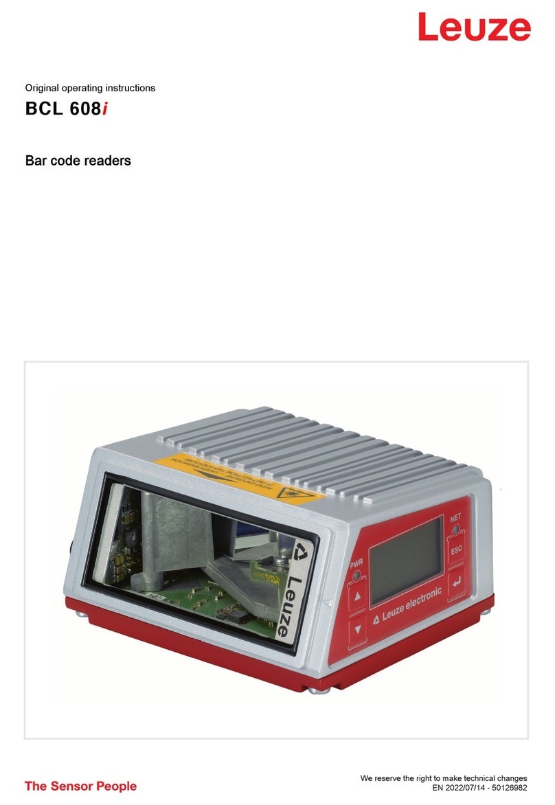
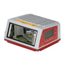
Leuze DCR 258i User manual

We reserve the right to make technical changes
EN • 2021-09-08 • 50145129
Original operating instructions
DCR 258i
Camera-based code reader

© 2021
Leuze electronic GmbH + Co. KG
In der Braike 1
73277 Owen / Germany
Phone: +49 7021 573-0
Fax: +49 7021 573-199
www.leuze.com
Leuze electronic GmbH + Co. KG DCR 258i 2

Table of contents
Leuze electronic GmbH + Co. KG DCR 258i 3
Table of contents
1 About this document ............................................................................................6
1.1 Used symbols and signal words ............................................................................................. 6
2 Safety .....................................................................................................................8
2.1 Intended use ...........................................................................................................................8
2.2 Foreseeable misuse ............................................................................................................... 8
2.3 Competent persons ................................................................................................................ 9
2.4 Disclaimer ............................................................................................................................... 9
3 Device description ..............................................................................................10
3.1 Device overview....................................................................................................................10
3.1.1 About the DCR200i code reader ......................................................................................10
3.1.2 Performance characteristics..............................................................................................10
3.1.3 Accessories .......................................................................................................................11
3.1.4 Device model with heating ................................................................................................11
3.2 Device construction .............................................................................................................. 12
3.3 Connection technology ......................................................................................................... 13
3.4 Indicators and operational controls....................................................................................... 13
3.4.1 LED indicators ...................................................................................................................15
3.4.2 Bar graph display ..............................................................................................................16
3.4.3 Control buttons ..................................................................................................................17
4 Functions.............................................................................................................18
4.1 Camera operating modes ..................................................................................................... 18
4.1.1 Single trigger mode ...........................................................................................................18
4.1.2 Reading gate control .........................................................................................................18
4.1.3 Burst mode ........................................................................................................................18
4.1.4 Presentation mode ............................................................................................................19
4.1.5 Continuous mode ..............................................................................................................19
4.2 Reference code comparison................................................................................................. 19
4.3 Code quality.......................................................................................................................... 20
4.4 Leuze webConfig tool ........................................................................................................... 21
5 Applications ........................................................................................................22
5.1 Reading of 1D-codes ............................................................................................................ 22
5.2 Reading of 2D-codes ............................................................................................................ 23
5.3 Code reading with polarization filter......................................................................................23
5.4 Code reading with diffusor foil .............................................................................................. 24
6 Mounting..............................................................................................................25
6.1 Determining the mounting position of the code reader ......................................................... 25
6.1.1 Selecting a mounting location ...........................................................................................25
6.1.2 Avoiding total reflection .....................................................................................................26
6.1.3 Determining the reading distance......................................................................................26
6.2 Mounting the code reader..................................................................................................... 47
6.2.1 Mounting with M4 fastening screws ..................................................................................47
6.2.2 Mounting with the BTU320M-D12 mounting system ........................................................47
6.2.3 Mounting with the BT320M mounting bracket ..................................................................47
6.2.4 Mounting with the BTU320M-D12-RL70 mounting bracket.............................................. 47
6.3 Replace housing hood .......................................................................................................... 48
6.4 Attaching the diffusor foil ...................................................................................................... 49

Table of contents
Leuze electronic GmbH + Co. KG DCR 258i 4
7 Electrical connection..........................................................................................50
7.1 Overview ............................................................................................................................... 51
7.2 PWR/SWIO ......................................................................................................................... 52
7.2.1 Voltage supply / switching inputs/outputs / RS232/RS422..............................................52
7.3 HOST - Host input / Ethernet................................................................................................ 55
7.4 Ethernet star topology........................................................................................................... 55
7.5 Cable lengths and shielding.................................................................................................. 57
7.6 Connecting code reader to fieldbus ...................................................................................... 57
7.7 Connecting code reader to MA150 connection unit............................................................. 57
8 Starting up the device – Basic configuration...................................................59
8.1 Measures to be performed prior to the initial commissioning ............................................... 59
8.2 Starting the device ................................................................................................................ 59
8.3 Setting the communication parameters ................................................................................ 60
8.3.1 Manually setting the IP address ........................................................................................60
8.3.2 Automatically setting the IP address .................................................................................61
8.3.3 Address Link Label............................................................................................................61
8.3.4 Ethernet host communication............................................................................................62
8.3.5 RS232/RS422 communication ........................................................................................63
8.3.6 FTP client ..........................................................................................................................63
8.4 Configuration via configuration codes................................................................................... 63
8.5 Activating device functions ................................................................................................... 63
8.6 Performing further settings ................................................................................................... 65
8.6.1 Decoding and processing the read data............................................................................65
8.6.2 Control of the decoding .....................................................................................................65
8.6.3 Activating camera operating mode....................................................................................66
8.6.4 Control of the switching outputs ........................................................................................66
8.6.5 Optimizing reading performance .......................................................................................66
8.6.6 Transfer configuration data ...............................................................................................67
9 Starting up the device – webConfig tool ..........................................................68
9.1 System requirements............................................................................................................ 68
9.2 Start webConfig tool ............................................................................................................. 68
9.3 Short description of the webConfigtool ................................................................................ 70
9.3.1 Change operating mode....................................................................................................70
9.3.2 Menu options of the webConfig tool ..................................................................................71
9.3.3 CONFIGURATION menu ..................................................................................................71
9.3.4 Configuring applications with the wizard ...........................................................................72
10 EtherNet/IP...........................................................................................................73
10.1 Overview ............................................................................................................................... 73
10.2 Manually setting the IP address............................................................................................ 74
10.3 Configuration for a Rockwell control without EDS support ................................................... 75
10.4 Configuration for a Rockwell control with EDS support ........................................................ 76
10.5 EDS file................................................................................................................................. 76
10.6 EDS object classes............................................................................................................... 77
10.6.1 Class1 – Identity object ....................................................................................................77
10.6.2 Class4 – Assembly...........................................................................................................78
10.6.3 Class103 – I/O status and control ....................................................................................84
10.6.4 Class106 – Activation.......................................................................................................86
10.6.5 Class107 – Result data ....................................................................................................87
10.6.6 Class108 – Entry data ......................................................................................................88
10.6.7 Class109 – Device status and device control...................................................................91
10.6.8 Class110 – Device application status and control............................................................91
Table of contents
Leuze electronic GmbH + Co. KG DCR 258i 5
10.6.9 Example configuration.......................................................................................................93
11 Interfaces – Communication..............................................................................96
11.1 Online commands................................................................................................................. 96
11.1.1 Overview of commands and parameters...........................................................................96
11.1.2 General online commands ................................................................................................97
11.1.3 Online commands for system control ..............................................................................101
11.2 XML-based communication ................................................................................................ 101
12 Care, maintenance and disposal .....................................................................102
13 Diagnostics and troubleshooting....................................................................103
14 Service and support .........................................................................................104
15 Technical data ...................................................................................................105
15.1 General specifications ........................................................................................................ 105
15.2 Optical data......................................................................................................................... 106
15.3 Code specifications............................................................................................................. 107
15.4 Device with heating............................................................................................................. 107
15.5 Dimensioned drawings ....................................................................................................... 107
15.6 Dimensioned drawings - Accessories................................................................................. 108
16 Order guide and accessories...........................................................................112
16.1 Nomenclature ..................................................................................................................... 112
16.2 Type overview..................................................................................................................... 113
16.3 Optical accessories............................................................................................................. 113
16.4 Cables accessories............................................................................................................. 113
16.5 Other accessories............................................................................................................... 115
17 EC Declaration of Conformity..........................................................................116
18 Appendix............................................................................................................117
18.1 ASCII character set............................................................................................................. 117
18.2 Code samples..................................................................................................................... 120
18.3 Configuration via configuration codes................................................................................. 122
18.4 License terms...................................................................................................................... 123

About this document
Leuze electronic GmbH + Co. KG DCR 258i 6
1 About this document
1.1 Used symbols and signal words
Tab.1.1: Warning symbols and signal words
Symbol indicating dangers to persons
NOTE Signal word for property damage
Indicates dangers that may result in property damage if the measures for dan-
ger avoidance are not followed.
CAUTION Signal word for minor injuries
Indicates dangers that may result in minor injury if the measures for danger
avoidance are not followed.
Tab.1.2: Other symbols
Symbol for tips
Text passages with this symbol provide you with further information.
Symbol for action steps
Text passages with this symbol instruct you to perform actions.
Tab.1.3: Terms and abbreviations
CIP Application protocol within Ethernet/IP
(Common Industrial Protocol)
CMOS Semiconductor process for implementing integrated circuits
(Complementary Metal-Oxide-Semiconductor)
DCR Camera-based code reader
(Dual Code Reader)
DHCP Process for automatically assigning the IP address
(Dynamic Host Configuration Protocol)
DLR Process for networking devices in a ring topology
(Device Level Ring)
EDS Standardized electronic data sheet
(Electronic Data Sheet)
EMC Electromagnetic compatibility
EN European standard
FE Functional earth
FOV Reading field of the code reader
(Field of View)
ICMP Process for exchanging information and error messages
(Internet Control Message Protocol)
IGMP Process for organizing multicast groups
(Internet Group Management Protocol)
IO or I/O Input/Output
(Input/Output)
IO controller Control that initiates the IO data communication

About this document
Leuze electronic GmbH + Co. KG DCR 258i 7
IP address Network address, which is based on the Internet Protocol (IP)
LED LED
(Light Emitting Diode)
MAC address Hardware address of a device in the network
(Media Access Control address)
ODVA User organization
(Open DeviceNet Vendor Association)
PCRE Regular expressions for reference code comparison
(Perl Compatible Regular Expressions)
PELV Protective extra low voltage with reliable disconnection
(Protective Extra Low Voltage)
ROI Working range of the code reader
(Region of Interest)
PLC Programmable Logic Control
(corresponds to Programmable Logic Controller (PLC))
TCP/IP Internet protocol family
(Transmission Control Protocol/Internet ProtocoI)
UDP Network transmission protocol
(User Datagram Protocol)
UL Underwriters Laboratories

Safety
Leuze electronic GmbH + Co. KG DCR 258i 8
2 Safety
This code reader was developed, manufactured and tested in accordance with the applicable safety stan-
dards. It corresponds to the state of the art.
2.1 Intended use
The code readers of the DCR200i series are camera-based code readers for all commonly used bar
codes, stacked codes and DataMatrix codes as well as for codes of the GS1DataBar family.
Areas of application
The code readers of the DCR200i series are especially designed for the following areas of application:
• Packaging systems
• Mounting/handling technology
• Analysis technology
CAUTION
Observe intended use!
The protection of personnel and the device cannot be guaranteed if the device is operated in a
manner not complying with its intended use.
ÄOnly operate the device in accordance with its intended use.
ÄLeuzeelectronicGmbH+Co.KG is not liable for damages caused by improper use.
ÄRead these operating instructions before commissioning the device. Knowledge of the oper-
ating instructions is an element of proper use.
NOTICE
Integrated illumination!
The code readers of the DCR200i series correspond to the following classification with respect
to the integrated illumination:
ÄRed illumination: Exempt group in acc. with EN62471
ÄInfrared illumination: Exempt group in acc. with EN62471
NOTICE
Comply with conditions and regulations!
ÄObserve the locally applicable legal regulations and the rules of the employer's liability insur-
ance association.
2.2 Foreseeable misuse
Any use other than that defined under "Intended use" or which goes beyond that use is considered im-
proper use.
In particular, use of the device is not permitted in the following cases:
• in rooms with explosive atmospheres
• in circuits which are relevant to safety
• in food processing (except device with stainless steel housing)
• for medical purposes

Safety
Leuze electronic GmbH + Co. KG DCR 258i 9
NOTICE
Do not modify or otherwise interfere with the device!
ÄDo not carry out modifications or otherwise interfere with the device.
The device must not be tampered with and must not be changed in any way.
ÄThe device may only be opened for exchanging the housing hood.
Stainless stainless steel housings must not be opened.
ÄThere are no user-serviceable parts inside the device.
ÄRepairs must only be performed by Leuze electronic GmbH + Co. KG.
2.3 Competent persons
Connection, mounting, commissioning and adjustment of the device must only be carried out by competent
persons.
Prerequisites for competent persons:
• They have a suitable technical education.
• They are familiar with the rules and regulations for occupational safety and safety at work.
• They are familiar with the operating instructions for the device.
• They have been instructed by the responsible person on the mounting and operation of the device.
Certified electricians
Electrical work must be carried out by a certified electrician.
Due to their technical training, knowledge and experience as well as their familiarity with relevant standards
and regulations, certified electricians are able to perform work on electrical systems and independently de-
tect possible dangers.
In Germany, certified electricians must fulfill the requirements of accident-prevention regulations DGUV
(German Social Accident Insurance) provision 3 (e.g. electrician foreman). In other countries, there are re-
spective regulations that must be observed.
2.4 Disclaimer
LeuzeelectronicGmbH+Co.KG is not liable in the following cases:
• The device is not being used properly.
• Reasonably foreseeable misuse is not taken into account.
• Mounting and electrical connection are not properly performed.
• Changes (e.g., constructional) are made to the device.

Device description
Leuze electronic GmbH + Co. KG DCR 258i 10
3 Device description
3.1 Device overview
3.1.1
About the DCR200i code reader
The code readers of the DCR200i series are camera-based code readers for all commonly used bar
codes, stacked codes and Data Matrix codes (e.g. Code128, EAN8/13, ECC200, QR etc.) as well as for
codes of the GS1DataBar family.
The extensive options for device configuration via control buttons, configuration codes or software enable
adaptation to a multitude of reading tasks. The high resolution in combination with a very high depth of field
as well as the compact design make the device ideal for use in packaging machines.
Code readers of the DCR200i series perform numerous tasks in industrial code reading such as:
• Omnidirectional code reading
• Reading of codes while at a standstill or in motion
• Manual reading by holding up codes
• In packaging machines
• In automatic handling and testing machines
The DCR2xxi code readers are available in several optics models:
• DCR2xxi with UltraHighDensity optics (U-optics)
• DCR2xxi with HighDensity optics (N-optics)
• DCR2xxi with MediumDensity optics (M-optics)
• DCR2xxi with LowDensity optics (F-optics)
• DCR2xxi with UltraLowDensity optics (L-optics)
The DCR2xxi code readers are operated as a “stand-alone” single device with individual IP address in an
Ethernet star topology.
Information on technical data and characteristics: see chapter 15 "Technical data".
3.1.2
Performance characteristics
• Decoding of 1D-, stacked- and 2D-codes
• Maximum depth of field and reading distance of approx. 40mm…800mm
• High object speed and decoding performance of up to 7m/s with 10decodings
• Reference code comparison
• Quality evaluation of 1D bar codes and 2D-codes in accordance with ISO/IEC15415 and ISO/
IEC15416
• Integrated process interfaces RS232, RS422 and Ethernet
The MA2xxi modular connection units are available for connecting to other fieldbus systems, e.g.,
PROFIBUS, PROFINET, EtherCAT, etc.
• Four freely programmable switching inputs/outputs for the activation or signaling of states:
• 1 switching input
• 1 switching output
• 2 switching inputs/outputs
• Optional: Robust stainless steel housing for use in the food and pharmaceutical industry; with lens
cover made of plastic or glass
• Integrated red LED illumination for illumination of the rectangular read field
• Green feedback LED for direct acknowledgment of whether the read process was successful
• Two control buttons for intuitive operation without PC
• Industrial design: degree of protection IP65 acc. to EN60529
(Device with stainless steel housing: degree of protection IP67/69K)
• Diverse mounting options with mounting threads on rear and side surfaces

Device description
Leuze electronic GmbH + Co. KG DCR 258i 11
• Variously coded M12 connections for unique assignment of the connections:
• Voltage supply, RS232/RS422, switching inputs/outputs
• Ethernet connection
• webConfig, a web-based configuration tool for configuration of all device parameters
No additional configuration software necessary
• Installation wizard for simple configuration in just a few steps
• Integrated teach functions for automatic adjustment of the exposure time, of the code types, and of the
number of digits and for teaching a reference code
3.1.3
Accessories
Special accessories are available for the code reader (see chapter 16 "Order guide and accessories"):
• Mounting systems for mounting
• Housing hood with integrated protective screen made of glass for increased protection against
scratches or welding sparks
• Housing hood with integrated linear polarisation filter – avoids additional interfering reflections
• Diffusor foil that can be affixed to housing hoods, with plastic or glass screen. The diffusor foil reduces
interfering reflections.
• Connection and interconnection cables for M12 connectors
• External illumination and mounting bracket for external illumination
For further information, contact your responsible Leuze subsidiary or Leuze customer service (see
chapter 14 "Service and support")
• MA2xxi modular connection units for connection to fieldbus systems (see chapter 7.6 "Connecting
code reader to fieldbus")
• MA150 modular connection unit for decentralized distribution of the signals (see chapter 7.7 "Connect-
ing code reader to MA150 connection unit")
• Connection to Ethernet switch
3.1.4
Device model with heating
The code reader is optionally available as a model with integrated heating. In this case, heating is perma-
nently installed ex works.
Features of the integrated heating:
• Extension of the application range -30°C…+50°C
• Supply voltage: 18V…30V DC
• Average power consumption: 12W

Device description
Leuze electronic GmbH + Co. KG DCR 258i 12
3.2 Device construction
1 1
2
3
4
5
6
7
8
3
2
3
4
5
6
7
8
3
1 Lens
2 Control panel with indicator LEDs, control buttons, bar graph display
Device with stainless steel housing: indicator LEDs
3 LEDs for illumination (red light)
4 M4 mounting thread
5 Device housing
6 Housing hood
7 M12 connection technology
8 Feedback LED (green)
Fig.3.1: Device construction

Device description
Leuze electronic GmbH + Co. KG DCR 258i 13
3.3 Connection technology
The device is connected using variously coded M12 connectors:
• A-coded, 12-pin, M12 connection for operating voltage, switching inputs/outputs, RS232/RS422 inter-
face
• D-coded, 4-pin, M12 connection for the Ethernet connection
PWR / SWIO HOST
1 2
1 PWR/SWIO, M12 plug, 12-pin, A-coded
2 HOST, M12 socket, 4-pin, D-coded
Fig.3.2: Electrical connections
NOTICE
Ready-made cables are available for all connections (see chapter 16.4 "Cables accessories").
NOTICE
Shielding connection!
ÄThe shielding is connected via the M12 connector housing.
3.4 Indicators and operational controls
NOTICE
Devices with stainless steel housing do not have any control buttons.
Devices with stainless steel housing do not have a bar graph indicator.
The device is equipped with the following indicators and operational controls:
• Feedback LED
The green feedback LED indicates whether a read process was successful. This function is activated
upon shipment of the device from the factory and can be deactivated via the webConfig tool.
Upon successful decoding, the feedback LED illuminates briefly (GOOD READ, MATCH).
• Three indicator LEDs (PWR, NET, LINK)
• Six-level bar graph display for function selection and display of the reading quality (SIGNALQUALITY)
– not with devices with stainless steel housing
• Two control buttons – not on devices with stainless steel housing

Device description
Leuze electronic GmbH + Co. KG DCR 258i 14
1 1
3
2
1 LED indicators: PWR, NET, LINK
2 Bar graph display
3 Control buttons
Fig.3.3: Layout of indicator and control panel

Device description
Leuze electronic GmbH + Co. KG DCR 258i 15
3.4.1
LED indicators
PWR LED
Tab.3.1: PWR indicators
Color State Description
--- OFF Device off
No operating voltage
Green Flashing Device ok
• Initialization phase
• Code reading not possible
• Operating voltage applied
• Self test running
ON (continuous light) Device ok
• Code reading possible
• Self test successfully finished
• Device monitoring active
Orange ON (continuous light) Service mode
• Code reading possible
• No data on the host interface
Flashing Wave function (synchronous with NET LED)
• Code reading possible
Red Flashing Device ok, warning set
• Code reading possible
• Temporary operating fault
ON (continuous light) Device error/parameter enable
No code reading possible
NET LED
Tab.3.2: NET indicators
Color State Description
--- OFF No operating voltage
• No communication possible
• Ethernet protocols not released
Green Flashing Initialization of the device
Establishing communication
ON (continuous light) Operation ok
• Network mode ok
• Connection and communication to Host established
Red Flashing Communication error
• Temporary connection error
• If DHCP active: No IP address could be obtained
ON (continuous light) Network error
• No connection established
• No communication possible

Device description
Leuze electronic GmbH + Co. KG DCR 258i 16
NOTICE
NET indicator only for Ethernet communication!
The NET indicator refers only to the Ethernet communication, not to the RS232/RS422.
LINK LED
Tab.3.3: LINK indicators
Color State Description
Green ON (continuous light) Ethernet connected (LINK)
Yellow Flashing Data communication (ACT)
3.4.2
Bar graph display
Function selection
NOTICE
Devices with stainless steel housing do not have any control buttons.
Devices with stainless steel housing do not have a bar graph indicator.
The following functions are selected and displayed via the bar graph display (see chapter 8.5 "Activating
device functions"):
•TRIG: Trigger function for activating a read process
•AUTO: Auto setup function for determining the optimum read setting
•ADJ: Adjustment function for aligning the device
•TEACH: Teach function for teaching a reference code
The individual functions are selected and activated with the control buttons.
• Select function with the navigation button : The function LED flashes.
• Activate function with the enter button : The function LED illuminates continuously.
NOTICE
A preselected function (flashing LED) does not yet have any influence on the functionality. If no
button is pressed for a longer period of time, flashing of the LED is ended automatically by the
device.
NOTICE
If you activate the TRIG, AUTO, ADJ or TEACH function via the control buttons, the device ac-
cepts no commands via the process interface. Process mode is thereby interrupted.
NOTICE
On devices with stainless steel housing, it is not possible to select functions using the control
buttons.

Device description
Leuze electronic GmbH + Co. KG DCR 258i 17
3.4.3
Control buttons
The functions of the bar graph display are controlled via the control buttons.
NOTICE
Devices with stainless steel housing do not have any control buttons.
Devices with stainless steel housing do not have a bar graph indicator.
NOTICE
In the Service operating mode (which is set using the webConfig tool), the code reader cannot
be operated using the control buttons.
• –Navigation button: Scroll through the functions in the bar graph display from left to right.
• –enter button: Scroll through the functions in the bar graph display.
NOTICE
A preselected function (flashing LED) does not yet have any influence on the functionality. If no
button is pressed for a longer period of time, flashing of the LED is ended automatically by the
device.
Example: Activation of the trigger
ÄPress the navigation button .
ðThe TRIG LED flashes and the Trigger function is preselected.
ÄPress the enter button .
ðThe TRIG LED illuminates continuously.
ðThe configured Trigger function (e.g., reading gate control) is started.

Functions
Leuze electronic GmbH + Co. KG DCR 258i 18
4 Functions
This chapter describes the functions of the code reader:
• Camera operating modes (see chapter 4.1 "Camera operating modes")
• Reference code comparison (see chapter 4.2 "Reference code comparison")
• Code quality (see chapter 4.3 "Code quality")
• webConfig tool (see chapter 4.4 "Leuze webConfig tool")
4.1 Camera operating modes
The camera operating mode defines how the code reader starts a read process and decodes the codes if a
code is located in the read field.
4.1.1
Single trigger mode
In the "Single trigger mode" camera operating mode, the code reader captures one image and attempts to
decode it. Under uniform conditions, this camera operating mode makes fast decoding possible.
4.1.2
Reading gate control
The "Reading gate control" camera operating mode is activated upon shipment from the factory. The read-
ing gate control opens a time window for the read process in the code reader – the reading gate. In this
time window, the code reader can capture and decode one or more codes.
4.1.3
Burst mode
In the "Burst mode" camera operating mode, the code reader captures multiple images in quick succession
after activation by a trigger signal.
• Decoding occurs following image capture, thereby allowing the codes to be detected more quickly.
• As soon as the decoding result corresponds to the settings, the decoding stops the capture of the re-
maining images.
A
A B C D
B C D E F G H A B DC
1
1
2
3
1 Continuous image capture
2 Decoding
3 Output of the read data
Fig.4.1: "Burst mode" camera operating mode

Functions
Leuze electronic GmbH + Co. KG DCR 258i 19
4.1.4
Presentation mode
In the "Presentation mode" camera operating mode, the code reader is in the idle state in a kind of wait
mode.
In the event of a change in the image area, e.g., by holding up a code, the code reader captures images
with illumination (as previously configured) until a code is read successfully. The code reader then switches
back to the wait mode and the illumination switches off after a few seconds.
Reading the same code multiple times
To prevent the same code from being read and output repeatedly in the "Presentation mode" camera oper-
ating mode, a delay time can be defined that must elapse before a code can be read again.
The delay time is set or deactivated with the webConfig tool (see chapter 9 "Starting up the device – web-
Config tool").
Configuration > Control > Reread delay
Sensitivity
This function can only be activated in the "Presentation mode" camera operating mode. You can set the
sensitivity threshold at which a change in the field of view is to be detected: 0…100.
• 0 = not sensitive
• 100 = sensitive
4.1.5
Continuous mode
In the "Continuous mode" camera operating mode, the code reader operates continuously in process
mode. In this mode, image acquisition is started again immediately after an image has been processed. An
external trigger signal is not required.
Image frequency
You can limit the maximum number of images per second. A reduction in image frequency is recom-
mended for slow applications where the object with the code moves slowly past the code reader. Consider
here the decoding time per decoding.
• It is recommended to limit the decoding time.
• It is recommended to deactivate the NOREAD output.
4.2 Reference code comparison
With the reference code comparison, the code reader compares the actual decoding result with a stored
reference code – the exact code content is compared.
Options for teaching-in a new reference code:
• webConfig tool: Configuration > Decoder > Reference
• Online command via the host interface
• Signal via a digital switching input
• TEACH function on the control panel of the code reader (not with devices with stainless steel housing)
In the webConfig tool, the exact code content can be entered for comparison.
Regular expressions
As an alternative to the exact code comparison, regular expressions can be used for a partial comparison.
Regular expressions can only be entered via the webConfig tool (see chapter 9 "Starting up the device –
webConfig tool").
Detailed information on regular expressions can be found on the Internet under Perl Compatible Regular
Expressions (PCRE) http://www.pcre.org/.
• Example1
The code reader is to perform a partial comparison of two characters "42". Any number of characters
and content may precede the string "42".
• Comparison string entered in the webConfig tool: 42
• Positive reference code comparison (match): 123425
• Negative reference code comparison (mismatch): 12345

Functions
Leuze electronic GmbH + Co. KG DCR 258i 20
• Example2
The code reader is to perform a partial comparison of two characters "42". Beginning with the string
"42", any number of characters and content may follow.
• Comparison string entered in the webConfig tool: ^42
• Positive reference code comparison (match): 42345
• Negative reference code comparison (mismatch): 12345
NOTICE
Using space characters with regular expressions!
ÄWhen entering regular expressions, note the use of space characters.
4.3 Code quality
Overview
To check the code quality, you can activate the Code quality function. This function determines the code
quality for bar codes and 2D-codes in compliance with ISO/IEC15416 and ISO/IEC15415.
NOTICE
Activating the Code quality function increases the decoding time.
The code quality is given as follows: A…F
• A = High quality
• F = Low quality
The following options are available:
• Determination of individual features for bar codes and 2D-codes
• Setting of a minimum quality (= NOMINALMINIMUM)
• Output of each feature via the interface and as a programmable switching output
ISO/IEC15416 mode: Individual features for bar codes
• Overall quality
• Symbol contrast (SC)
• Modulation (MOD)
• Decodability
• Minimal edge contrast (ECmin)
• Minimal reflectance (Rmin)
• Defects
• Decodes
Table of contents
Other Leuze Barcode Reader manuals

Leuze
Leuze BPS 3007i User manual

Leuze
Leuze IT 3800g User manual

Leuze
Leuze BPS 348i User manual

Leuze
Leuze HS 6578 User manual

Leuze
Leuze DCR 55 User manual

Leuze
Leuze IT 6320 DPM Setup guide

Leuze
Leuze BCL 8 User manual

Leuze
Leuze BCL604i User manual

Leuze
Leuze BCL 92 User manual

Leuze
Leuze BCL 608i SM 102 User manual

Leuze
Leuze BPS 3048i User manual

Leuze
Leuze BCL34 Parts list manual

Leuze
Leuze BCL 40 Parts list manual

Leuze
Leuze it 3820 User manual

Leuze
Leuze CR 100 User manual

Leuze
Leuze BPS 34 User manual

Leuze
Leuze BCL 900i User manual

Leuze
Leuze it 1452g User manual

Leuze
Leuze BCL 208i User manual

Leuze
Leuze BCL 308i User manual